EP0046339B2 - Master cylinder - Google Patents
Master cylinder Download PDFInfo
- Publication number
- EP0046339B2 EP0046339B2 EP81303323A EP81303323A EP0046339B2 EP 0046339 B2 EP0046339 B2 EP 0046339B2 EP 81303323 A EP81303323 A EP 81303323A EP 81303323 A EP81303323 A EP 81303323A EP 0046339 B2 EP0046339 B2 EP 0046339B2
- Authority
- EP
- European Patent Office
- Prior art keywords
- sleeve
- flange
- master cylinder
- passageway
- reservoir
- Prior art date
- Legal status (The legal status is an assumption and is not a legal conclusion. Google has not performed a legal analysis and makes no representation as to the accuracy of the status listed.)
- Expired - Lifetime
Links
- 239000012530 fluid Substances 0.000 claims description 7
- 238000007789 sealing Methods 0.000 claims description 2
- 238000010276 construction Methods 0.000 description 6
- 238000000465 moulding Methods 0.000 description 4
- 239000002184 metal Substances 0.000 description 2
- 229910000831 Steel Inorganic materials 0.000 description 1
- 230000003466 anti-cipated effect Effects 0.000 description 1
- 238000005266 casting Methods 0.000 description 1
- 238000002788 crimping Methods 0.000 description 1
- 238000004512 die casting Methods 0.000 description 1
- 238000005553 drilling Methods 0.000 description 1
- 230000009977 dual effect Effects 0.000 description 1
- 238000003754 machining Methods 0.000 description 1
- 238000004519 manufacturing process Methods 0.000 description 1
- 239000000463 material Substances 0.000 description 1
- 239000002991 molded plastic Substances 0.000 description 1
- 239000004033 plastic Substances 0.000 description 1
- 229920003023 plastic Polymers 0.000 description 1
- 238000000926 separation method Methods 0.000 description 1
- 239000010959 steel Substances 0.000 description 1
- 230000003313 weakening effect Effects 0.000 description 1
Images

Classifications
-
- B—PERFORMING OPERATIONS; TRANSPORTING
- B60—VEHICLES IN GENERAL
- B60T—VEHICLE BRAKE CONTROL SYSTEMS OR PARTS THEREOF; BRAKE CONTROL SYSTEMS OR PARTS THEREOF, IN GENERAL; ARRANGEMENT OF BRAKING ELEMENTS ON VEHICLES IN GENERAL; PORTABLE DEVICES FOR PREVENTING UNWANTED MOVEMENT OF VEHICLES; VEHICLE MODIFICATIONS TO FACILITATE COOLING OF BRAKES
- B60T13/00—Transmitting braking action from initiating means to ultimate brake actuator with power assistance or drive; Brake systems incorporating such transmitting means, e.g. air-pressure brake systems
- B60T13/10—Transmitting braking action from initiating means to ultimate brake actuator with power assistance or drive; Brake systems incorporating such transmitting means, e.g. air-pressure brake systems with fluid assistance, drive, or release
- B60T13/24—Transmitting braking action from initiating means to ultimate brake actuator with power assistance or drive; Brake systems incorporating such transmitting means, e.g. air-pressure brake systems with fluid assistance, drive, or release the fluid being gaseous
- B60T13/46—Vacuum systems
- B60T13/52—Vacuum systems indirect, i.e. vacuum booster units
- B60T13/565—Vacuum systems indirect, i.e. vacuum booster units characterised by being associated with master cylinders, e.g. integrally formed
-
- B—PERFORMING OPERATIONS; TRANSPORTING
- B60—VEHICLES IN GENERAL
- B60T—VEHICLE BRAKE CONTROL SYSTEMS OR PARTS THEREOF; BRAKE CONTROL SYSTEMS OR PARTS THEREOF, IN GENERAL; ARRANGEMENT OF BRAKING ELEMENTS ON VEHICLES IN GENERAL; PORTABLE DEVICES FOR PREVENTING UNWANTED MOVEMENT OF VEHICLES; VEHICLE MODIFICATIONS TO FACILITATE COOLING OF BRAKES
- B60T11/00—Transmitting braking action from initiating means to ultimate brake actuator without power assistance or drive or where such assistance or drive is irrelevant
- B60T11/10—Transmitting braking action from initiating means to ultimate brake actuator without power assistance or drive or where such assistance or drive is irrelevant transmitting by fluid means, e.g. hydraulic
- B60T11/16—Master control, e.g. master cylinders
- B60T11/22—Master control, e.g. master cylinders characterised by being integral with reservoir
Definitions
- This invention relates to master cylinders for vehicle braking systems, and in particular to a master cylinder which comprises a body with an axial bore open at the rear end of the body, a flange on the body, a reservoir mounted on the body in front of the flange, the reservoir enclosing a reservoir chamber, a transverse port in the body opening into the bore and positioned rearwardly of the reservoir chamber and the flange, and a passage communicating said reservoir chamber with said transverse port.
- a master cylinder of the above form is proposed in our copending British Patent Application No. 8108215 (Publication No. 2052656) and the advantage of this construction is that it allows the reservoir to be located at the forward end of the body, whereby the rear end of the master cylinder can be received within an actuating servo-booster and an overall space saving achieved.
- the transverse port which is normally open to a pressure chamber defined in the bore of the master cylinder body, communicates with the reservoir chamber through a longitudinal passageway extending through the wall of the body parallel to the bore axis, the passageway extending forwardly from an internal shoulder formed in the bore to the reservoir chamber and intersecting the transverse port.
- a master cylinder according to the preamble of claims 1 and 4 for a braking system in which a rear end part of the master cylinder body located behind the mounting flange is accommodated within a servo-booster.
- a passageway interconnecting the reservoir with a transverse port located at a position rearwardly of the flange has a minor portion, which is spaced at a distance rearwardly from the flange, formed by a circumferential groove in the body and a separate cylindrical sleeve covering the groove.
- the major part of the passageway is formed by a longitudinal duct extending through the wall of the body from the forwardmost side wall of the groove.
- the invention aims at avoiding the problems of the previously proposed construction and in accordance with one embodiment the invention provides a master cylinder comprising a body with an axial bore open at the rear end of the body, a flange on the body for supporting the body, a reservoir mounted on the body in front of the flange, the reservoir enclosing a reservoir chamber, a transverse port in the body opening into the bore and positioned rearwardly of the reservoir chamber and the flange, a passageway communicating said reservoir chamber with said transverse port for conducting brake fluid between the reservoir chamber and the bore, part of said passageway being defined outside of the body by a sleeve sealingly mounted on the body and covering a portion of the body located rearwardly of the flange, and a port defining a remaining part of said passageway, said port connecting the space between the body and the forward end of the sleeve to the reservoir chamber, characterised in that the forward end of the sleeve is sealingly engaged with the rear face of the flange at a position
- the invention provides a master cylinder comprising a body with an axial bore open at the rear end of the body, a flange on the body for supporting the body, a reservoir mounted on the body in front of the flange, the reservoir enclosing a reservoir chamber, a transverse port in the body opening into the bore and positioned rearwardly of the reservoir chamber and the flange, and a passageway communicating said reservoir chamber with said transverse port for conducting brake fluid between the reservoir chamber and the bore, part of said passageway being defined outside of the body by a sleeve mounted on the body and covering a portion of the body located rearwardly of the flange, characterised in that a through duct formed in a member made separately from the body and carried thereon defines the remaining part of said passageway and connects the forward end of said passageway part defined by the sleeve directly to the reservoir chamber, said duct passing either through or outwardly of said flange.
- the master cylinder constructions according to the invention allow all the problems associated with drilling a longitudinal pasgeway in the body wall to be positively eliminated.
- the sleeve is preferably provided with at least one longitudinal groove on its internal surface to define the passageway.
- Grooves are comparatively simple to produced on the inside of the sleeve, either during moulding in the case of a plastics sleeve, or by crimping to form flutes in the case of a pressed metal sleeve.
- the forward end of the sleeve is received in an annular groove formed in the rear face of the flange, and a seal is accommodated in the groove for sealing the sleeve to the flange.
- the sleeve projects beyond the rear end of the body and is sealed to the actuating rod protruding through the open end of the master cylinder bore, since the passageway may then also serve to communicate, via the end of the body, the reservoir chamber with a recuperation chamber defined in the bore behind the piston.
- a master cylinder in a master cylinder according to said further embodiment said member carried by the body can be integral with the sleeve, whereby the sleeve includes a forwardly projecting part integral therewith and defining said duct.
- the master cylinder is to be assembled with a booster the sleeve and said member mounted on the body can be made integral with the booster housing, whereby the need for a separate member is eliminated and a simpler construction obtained.
- the sleeve, a front part of the booster housing and at a least a part of the reservoir housing are formed by a unitary part incorporating said duct. With these parts made in a single moulding manufacture and assembly are further simplified.
- the member carried on the body may be an element interposed between the body and the sleeve mounted thereon, the element having a tubular extension defining said duct.
- the element may be a tubular liner which is a sliding fit on the body and the sleeve may be a metal sleeve which is a sliding fit on the liner.
- the sleeve mounted on the body over the element can comprise a separate sleeve or part of a booster housing as described above.
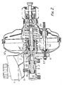
- the tandem master cylinder illustrated in Figure 1 is intended for a dual circuit braking system and comprises an integrally cast or moulded housing 1 including a body 2 with an axial blind bore 3 open at the rear end of the body, a reservoir 4 divided internally by a baffle 5 into two chambers 6, 7 and a flange 8 for mounting the master cylinder to a booster or other vehicle component.
- a piston 9 separates the bore into front and rear pressure chambers 10, 11 and is coupled to a second piston 12 formed integrally with a hollow actuating rod 13, by a telescopic device 14 which limits separation of the pistons, a spring 15 and serving to urge the pistons axially apart.
- a port 16 connects the reservoir chamber 6 to the front pressure chamber 10 in the illustrated unactuated condition of the master cylinder, while a further transverse port 17 extending through the body 2 connects with the rear pressure chamber 11.
- the mounting flange 8 is provided with a groove extending about the body 2 and a port 18 connects the groove with the reservoir chamber 7.
- a sleeve 20 is fitted over the rear of the body 2, the forward end of the sleeve being received in the groove of flange 8 and sealed to the outer wall of the groove by an O-ring seal 21.
- a medial portion 22 of the sleeve is crimped or fluted to define axially extending internal fins 23 which slidably engage the outer surface of the body 2.
- the rear end of the sleeve 20 is sealed to the actuating rod by a seal 24 which is supported by a seal support member 25 held against the end of the master cylinder housing by an internal shoulder on the sleeve.
- the member 25 has radial grooves 26 which connect the passages defined between the fins 23 of sleeve 20 with a recuperation chamber 27 for the seal of piston 12.
- the sleeve 20 is held in position by the main return spring 28 which is interposed between an external shoulder on the sleeve and a collar 29 fitted on the actuating rod.
- the sleeve 20 and the external surface of the body 2 define a passageway communicating reservoir chamber 7 with the transverse port 17 and the recuperation chamber 27.
- the reservoir 4 may be made separately and connected to the body which is provided with the usual connecting boss. In either case port 18 can be formed during casting or moulding so that a subsequent machining step is unnecessary.
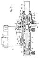
- FIG 2 there is shown a master cylinder of the same basic form to that described with reference to Figure 1, in combination with a booster.
- the booster is of known construction and a detailed description of its construction and operation is not considered necessary here.
- the booster housing is formed in two halves in well known manner.
- the front half or part 50 of the housing includes a central tubular portion or sleeve 51 defining a cylindrical recess in which the rear end of the master cylinder body 2 is received so that its mounting flange 8 abuts the front surface of the booster housing and against which it is clamped by the bolts 52 and nuts 53.
- the booster housing is sealed to body 2 by a seal 21 located adjacent the mounting flange 8 and a further seal 24 seals the rear end of sleeve 51 to the actuating rod 13 of the master cylinder which projects through the rear end of body 2.
- a lower part 54, at least, of the master cylinder reservoir 4 is made integrally with the booster housing part 50 and a passageway 18 is included to communicate the reservoir chamber 7 with a longitudinal groove 55 provided on the inside surface of the sleeve 51 and in register with the rear transverse port 17 of the master cylinder.
- the booster housing and master cylinder body define between them a passage connecting port 17 and reservoir chamber 7.
- the port 17 intersects a groove 17A provided in the wall of the master cylinder bore so that the port communicates with the bore on both sides of the piston seal, whereby a further passage for communicating the reservoir with the recuperation chamber 27 defined in the bore 3 behind the seal of rear piston 12 is no longer necessary.
- the booster housing part 50 including the reservoir and central tubular sleeve 51 as well as the passageway 18 may be moulded from pastics material or, alternatively, may consist of a die-casting.
- the reservoir housing 4 is formed separately from the body 2 rather than integral with it as in Figure 1.
- the housing 4 is located on the body by a pin 60 which passes through the wall of body 2 and forms a stop for piston 9, a port 61 leading from reservoir chamber 6 being in register with port 16 in the body, and a port 18 leading from reservoir chamber 7 being aligned with a hole 63 through the master cylinder mounting flange 8.
- the reservoir housing 4 is held on the body 2 by one or more clips (not shown).
- the liner 64 Fitted over the end of the body rearwardly of the flange 8 is moulded plastics liner 64 of essentially cup-shape with an axial opening through which the actuating rod 13 passes.
- the liner 64 includes a longitudinal slot 65 which extends radially the full thickness of the liner, and a forwardly projecting integral tube 66 protruding through the hole 63 in flange 8 and into reservoir port to which it is sealed by a seal 67.
- the slot 65 communicates at its forward end with the duct 18′ of tube 66, intersects the transverse port 17 in body 2, and communicates at its rear end with the recuperation chamber 27 behind piston 12.
- an outer sleeve 68 for example, of pressed steel, seals 69 and 70 being interposed between the sleeve 68 and the liner at a position in front of slot 65 and between the sleeve 68 and the actuating rod 13, respectively.
- a further seal 71 is placed between the liner 64 and the body 2.
- the slot 65 in the liner which is closed on the outside by the sleeve 68, defines with the duct 18′ through the tubular extension 66 a passageway communicating the reservoir chamber 7 with the transverse port 17 and with the recuperation chamber 27.
Landscapes
- Engineering & Computer Science (AREA)
- Transportation (AREA)
- Mechanical Engineering (AREA)
- Transmission Of Braking Force In Braking Systems (AREA)
Applications Claiming Priority (6)
| Application Number | Priority Date | Filing Date | Title |
|---|---|---|---|
| GB8026497 | 1980-08-14 | ||
| GB8026497 | 1980-08-14 | ||
| GB8110573 | 1981-04-03 | ||
| GB8110573 | 1981-04-03 | ||
| GB8113362 | 1981-04-30 | ||
| GB8113362 | 1981-04-30 |
Publications (3)
| Publication Number | Publication Date |
|---|---|
| EP0046339A1 EP0046339A1 (en) | 1982-02-24 |
| EP0046339B1 EP0046339B1 (en) | 1984-10-31 |
| EP0046339B2 true EP0046339B2 (en) | 1992-04-01 |
Family
ID=27260990
Family Applications (1)
| Application Number | Title | Priority Date | Filing Date |
|---|---|---|---|
| EP81303323A Expired - Lifetime EP0046339B2 (en) | 1980-08-14 | 1981-07-21 | Master cylinder |
Country Status (8)
Families Citing this family (11)
| Publication number | Priority date | Publication date | Assignee | Title |
|---|---|---|---|---|
| CA1194522A (en) * | 1981-05-14 | 1985-10-01 | Robert F. Gaiser | Master cylinder |
| US4474005A (en) | 1982-08-26 | 1984-10-02 | The Bendix Corporation | Master cylinder |
| FR2561320B1 (fr) * | 1984-03-19 | 1986-09-19 | Wabco Freinage Vehicules Sa | Emetteur de pression hydraulique et son joint annulaire d'etancheite |
| GB8720529D0 (en) * | 1987-09-01 | 1987-10-07 | Lucas Ind Plc | Master cylinder |
| DE8810531U1 (de) * | 1988-08-19 | 1989-12-21 | Lucas Industries P.L.C., Birmingham, West Midlands | Bremsbetätigungs-Baugruppe für Kraftfahrzeuge |
| FR2649947A1 (fr) * | 1989-07-19 | 1991-01-25 | Bendix France | Ensemble compose d'un servomoteur pneumatique, d'un maitre-cylindre et d'un reservoir |
| DE4202820C2 (de) * | 1992-01-31 | 1996-09-05 | Lucas Ind Plc | Betätigungseinheit für Kraftfahrzeugbremsen |
| US5329769A (en) * | 1993-07-16 | 1994-07-19 | Alliedsignal Inc. | Master cylinder and brake booster arrangement for a brake system |
| DE502004003235D1 (de) * | 2003-08-20 | 2007-04-26 | Continental Teves Ag & Co Ohg | Betätigungseinheit für eine hydraulische fahrzeugbremse |
| US8677746B2 (en) | 2010-09-02 | 2014-03-25 | Robert Bosch Gmbh | Master cylinder and brake booster assembly |
| FR3072349B1 (fr) * | 2017-10-12 | 2020-03-06 | Robert Bosch Gmbh | Bloc hydraulique de servofrein electrohydraulique |
Family Cites Families (17)
| Publication number | Priority date | Publication date | Assignee | Title |
|---|---|---|---|---|
| US1985588A (en) * | 1931-04-28 | 1934-12-25 | John W Tatter | Brake |
| US1945728A (en) * | 1931-07-01 | 1934-02-06 | Alanson P Brush | Hydraulic brake |
| GB422214A (en) * | 1933-07-21 | 1935-01-08 | British Leyland Motor Corp | Hydraulic brakes |
| US2162797A (en) * | 1937-12-15 | 1939-06-20 | Wagner Electric Corp | Combined compressor and power cylinder |
| US2224125A (en) * | 1938-08-19 | 1940-12-10 | Wagner Electric Corp | Fluid compressor |
| FR921176A (fr) * | 1946-11-29 | 1947-04-29 | Cylindre de commande pour frein ou autre dispositif hydraulique | |
| US2759329A (en) * | 1952-05-19 | 1956-08-21 | Joseph V Ponti | Master cylinder pressure cartridge unit |
| US2977767A (en) * | 1958-06-11 | 1961-04-04 | Glenn T Randol | Master cylinder for hydraulic brake systems |
| US3044267A (en) * | 1960-01-07 | 1962-07-17 | James M Hicks | Throttle control |
| GB900327A (en) * | 1960-11-11 | 1962-07-04 | Cox Of Watford Ltd | Improvements in or relating to hydraulic clamping or piercing systems and the like |
| US3186174A (en) * | 1963-04-30 | 1965-06-01 | Holley Carburetor Co | Hydraulic master cylinder |
| FR1406357A (fr) * | 1964-09-02 | 1965-07-16 | Robertbosch G M B H | Amplificateur de force de freinage à fluide sous pression pour dispositifs de freinage hydraulique |
| GB1065599A (en) * | 1965-02-03 | 1967-04-19 | Automotive Prod Co Ltd | Improvements in and relating to master cylinders for hydraulic systems |
| DE1675250A1 (de) * | 1968-01-23 | 1971-04-15 | Teves Gmbh Alfred | Stehend angeordneter Hauptzylinder |
| GB1481612A (en) * | 1975-04-07 | 1977-08-03 | Automotive Prod Co Ltd | Liquid pressure master cylinders |
| DE2918912A1 (de) * | 1979-05-10 | 1980-12-11 | Teves Gmbh Alfred | Bremskraftverstaerker |
| GB2052656A (en) * | 1979-06-12 | 1981-01-28 | Lucas Industries Ltd | Master Cylinder |
-
1981
- 1981-07-20 AU AU73135/81A patent/AU543605B2/en not_active Ceased
- 1981-07-21 EP EP81303323A patent/EP0046339B2/en not_active Expired - Lifetime
- 1981-07-21 DE DE8181303323T patent/DE3166954D1/de not_active Expired
- 1981-07-25 KR KR1019810002702A patent/KR860000621B1/ko not_active Expired
- 1981-08-05 IN IN139/MAS/81A patent/IN153873B/en unknown
- 1981-08-12 BR BR8105187A patent/BR8105187A/pt unknown
- 1981-08-13 ES ES504742A patent/ES8301157A1/es not_active Expired
-
1985
- 1985-08-09 US US06/764,509 patent/US4827720A/en not_active Expired - Lifetime
Also Published As
| Publication number | Publication date |
|---|---|
| US4827720A (en) | 1989-05-09 |
| AU7313581A (en) | 1982-02-18 |
| EP0046339A1 (en) | 1982-02-24 |
| EP0046339B1 (en) | 1984-10-31 |
| KR830006043A (ko) | 1983-09-17 |
| ES504742A0 (es) | 1982-12-01 |
| BR8105187A (pt) | 1982-04-27 |
| IN153873B (GUID-C5D7CC26-194C-43D0-91A1-9AE8C70A9BFF.html) | 1984-08-25 |
| AU543605B2 (en) | 1985-04-26 |
| KR860000621B1 (ko) | 1986-05-24 |
| DE3166954D1 (en) | 1984-12-06 |
| ES8301157A1 (es) | 1982-12-01 |
Similar Documents
| Publication | Publication Date | Title |
|---|---|---|
| GB2082277A (en) | Master Cylinder | |
| US4450688A (en) | Brake booster for automotive vehicles | |
| EP0046339B2 (en) | Master cylinder | |
| US4566275A (en) | Hydraulic boosters for vehicle braking systems | |
| US3312147A (en) | Fluid pressure servomotor | |
| EP0164198B1 (en) | Pneumatic brake booster | |
| EP0073722B1 (en) | Master cylinder | |
| US4729289A (en) | Power brake booster for an automotive vehicle | |
| JPS584664A (ja) | 流体加圧装置 | |
| GB2052656A (en) | Master Cylinder | |
| EP0192346B1 (en) | Servo-assisted master cylinder assemblies | |
| EP0065891A1 (en) | Master cylinder | |
| EP0074874B1 (en) | Fast-fill master cylinder | |
| US4887517A (en) | Master cylinder with piston retainer | |
| EP0221807B1 (en) | Hydraulic brake booster with quick take-up and full stroke | |
| US4258549A (en) | Master cylinder | |
| US4571943A (en) | Tandem brake booster with hydraulic mechanism for rear diaphragm force reversal | |
| US4984507A (en) | Three chamber brake booster with variable pressure passages having a minimum channel length | |
| JPH0143660B2 (GUID-C5D7CC26-194C-43D0-91A1-9AE8C70A9BFF.html) | ||
| US5590527A (en) | Master cylinder with tie rod mounted end plate | |
| US6516702B1 (en) | Brake booster | |
| EP0242085B1 (en) | Compressed air-operated servo-booster | |
| JPS5934547B2 (ja) | マスタシリンダ | |
| US5247868A (en) | Brake booster of tandem type | |
| GB2239915A (en) | A master cylinder |
Legal Events
| Date | Code | Title | Description |
|---|---|---|---|
| PUAI | Public reference made under article 153(3) epc to a published international application that has entered the european phase |
Free format text: ORIGINAL CODE: 0009012 |
|
| AK | Designated contracting states |
Designated state(s): DE FR IT |
|
| 17P | Request for examination filed |
Effective date: 19820628 |
|
| RAP1 | Party data changed (applicant data changed or rights of an application transferred) |
Owner name: LUCAS INDUSTRIES PLC |
|
| ITF | It: translation for a ep patent filed | ||
| GRAA | (expected) grant |
Free format text: ORIGINAL CODE: 0009210 |
|
| AK | Designated contracting states |
Designated state(s): DE FR IT |
|
| REF | Corresponds to: |
Ref document number: 3166954 Country of ref document: DE Date of ref document: 19841206 |
|
| ET | Fr: translation filed | ||
| PLBI | Opposition filed |
Free format text: ORIGINAL CODE: 0009260 |
|
| 26 | Opposition filed |
Opponent name: SOCIETE ANOMYME D.B.A. Effective date: 19850415 |
|
| PLAB | Opposition data, opponent's data or that of the opponent's representative modified |
Free format text: ORIGINAL CODE: 0009299OPPO |
|
| R26 | Opposition filed (corrected) |
Opponent name: BENDIX FRANCE Effective date: 19850415 |
|
| PLAB | Opposition data, opponent's data or that of the opponent's representative modified |
Free format text: ORIGINAL CODE: 0009299OPPO |
|
| R26 | Opposition filed (corrected) |
Opponent name: BENDIX FRANCE Effective date: 19850415 |
|
| ITTA | It: last paid annual fee | ||
| PUAH | Patent maintained in amended form |
Free format text: ORIGINAL CODE: 0009272 |
|
| STAA | Information on the status of an ep patent application or granted ep patent |
Free format text: STATUS: PATENT MAINTAINED AS AMENDED |
|
| 27A | Patent maintained in amended form |
Effective date: 19920401 |
|
| AK | Designated contracting states |
Kind code of ref document: B2 Designated state(s): DE FR IT |
|
| ITF | It: translation for a ep patent filed | ||
| ET3 | Fr: translation filed ** decision concerning opposition | ||
| APAC | Appeal dossier modified |
Free format text: ORIGINAL CODE: EPIDOS NOAPO |
|
| APAC | Appeal dossier modified |
Free format text: ORIGINAL CODE: EPIDOS NOAPO |
|
| PGFP | Annual fee paid to national office [announced via postgrant information from national office to epo] |
Ref country code: FR Payment date: 20000519 Year of fee payment: 20 |
|
| PGFP | Annual fee paid to national office [announced via postgrant information from national office to epo] |
Ref country code: DE Payment date: 20000725 Year of fee payment: 20 |
|
| APAH | Appeal reference modified |
Free format text: ORIGINAL CODE: EPIDOSCREFNO |