EP0046112B1 - Vorrichtungen und Systeme zum Aufwerten thermischer Energie mit niedrigem Niveau unter Ausnutzung der Verdampfung, und Mischung zweier strömender Medien mit gleichem Dampfdruck bei unterschiedlichen Temperaturen - Google Patents
Vorrichtungen und Systeme zum Aufwerten thermischer Energie mit niedrigem Niveau unter Ausnutzung der Verdampfung, und Mischung zweier strömender Medien mit gleichem Dampfdruck bei unterschiedlichen Temperaturen Download PDFInfo
- Publication number
- EP0046112B1 EP0046112B1 EP81401260A EP81401260A EP0046112B1 EP 0046112 B1 EP0046112 B1 EP 0046112B1 EP 81401260 A EP81401260 A EP 81401260A EP 81401260 A EP81401260 A EP 81401260A EP 0046112 B1 EP0046112 B1 EP 0046112B1
- Authority
- EP
- European Patent Office
- Prior art keywords
- temperature
- source
- heat
- evaporation
- liquid
- Prior art date
- Legal status (The legal status is an assumption and is not a legal conclusion. Google has not performed a legal analysis and makes no representation as to the accuracy of the status listed.)
- Expired
Links
- 238000001704 evaporation Methods 0.000 title claims description 28
- 230000008020 evaporation Effects 0.000 title claims description 26
- 239000012530 fluid Substances 0.000 title claims description 20
- 239000007788 liquid Substances 0.000 claims description 24
- 238000009833 condensation Methods 0.000 claims description 23
- 230000005494 condensation Effects 0.000 claims description 22
- 239000000203 mixture Substances 0.000 claims description 6
- 229910052751 metal Inorganic materials 0.000 claims description 3
- 239000002184 metal Substances 0.000 claims description 3
- 238000011084 recovery Methods 0.000 claims description 3
- 238000000926 separation method Methods 0.000 claims description 3
- XLYOFNOQVPJJNP-UHFFFAOYSA-N water Substances O XLYOFNOQVPJJNP-UHFFFAOYSA-N 0.000 description 48
- 239000000243 solution Substances 0.000 description 27
- 238000009434 installation Methods 0.000 description 21
- 239000002904 solvent Substances 0.000 description 18
- HPALAKNZSZLMCH-UHFFFAOYSA-M sodium;chloride;hydrate Chemical class O.[Na+].[Cl-] HPALAKNZSZLMCH-UHFFFAOYSA-M 0.000 description 17
- 239000012267 brine Substances 0.000 description 16
- 239000013529 heat transfer fluid Substances 0.000 description 9
- QAOWNCQODCNURD-UHFFFAOYSA-N Sulfuric acid Chemical compound OS(O)(=O)=O QAOWNCQODCNURD-UHFFFAOYSA-N 0.000 description 7
- 238000010521 absorption reaction Methods 0.000 description 7
- KWGKDLIKAYFUFQ-UHFFFAOYSA-M lithium chloride Chemical compound [Li+].[Cl-] KWGKDLIKAYFUFQ-UHFFFAOYSA-M 0.000 description 7
- UXVMQQNJUSDDNG-UHFFFAOYSA-L Calcium chloride Chemical compound [Cl-].[Cl-].[Ca+2] UXVMQQNJUSDDNG-UHFFFAOYSA-L 0.000 description 6
- 239000013505 freshwater Substances 0.000 description 6
- 238000010438 heat treatment Methods 0.000 description 6
- 239000001110 calcium chloride Substances 0.000 description 5
- 229910001628 calcium chloride Inorganic materials 0.000 description 5
- 238000010276 construction Methods 0.000 description 5
- 238000010586 diagram Methods 0.000 description 5
- 238000004090 dissolution Methods 0.000 description 5
- 150000003839 salts Chemical class 0.000 description 5
- 238000009834 vaporization Methods 0.000 description 5
- 230000008016 vaporization Effects 0.000 description 5
- JIAARYAFYJHUJI-UHFFFAOYSA-L zinc dichloride Chemical compound [Cl-].[Cl-].[Zn+2] JIAARYAFYJHUJI-UHFFFAOYSA-L 0.000 description 5
- HEMHJVSKTPXQMS-UHFFFAOYSA-M Sodium hydroxide Chemical compound [OH-].[Na+] HEMHJVSKTPXQMS-UHFFFAOYSA-M 0.000 description 4
- 238000002156 mixing Methods 0.000 description 4
- 239000003507 refrigerant Substances 0.000 description 4
- 238000005057 refrigeration Methods 0.000 description 4
- QGZKDVFQNNGYKY-UHFFFAOYSA-N Ammonia Chemical compound N QGZKDVFQNNGYKY-UHFFFAOYSA-N 0.000 description 3
- 239000007789 gas Substances 0.000 description 3
- 239000012047 saturated solution Substances 0.000 description 3
- CDBYLPFSWZWCQE-UHFFFAOYSA-L Sodium Carbonate Chemical compound [Na+].[Na+].[O-]C([O-])=O CDBYLPFSWZWCQE-UHFFFAOYSA-L 0.000 description 2
- FAPWRFPIFSIZLT-UHFFFAOYSA-M Sodium chloride Chemical compound [Na+].[Cl-] FAPWRFPIFSIZLT-UHFFFAOYSA-M 0.000 description 2
- 241001080024 Telles Species 0.000 description 2
- 238000001816 cooling Methods 0.000 description 2
- 238000005260 corrosion Methods 0.000 description 2
- 230000007797 corrosion Effects 0.000 description 2
- AMXOYNBUYSYVKV-UHFFFAOYSA-M lithium bromide Chemical compound [Li+].[Br-] AMXOYNBUYSYVKV-UHFFFAOYSA-M 0.000 description 2
- 230000008929 regeneration Effects 0.000 description 2
- 238000011069 regeneration method Methods 0.000 description 2
- 239000013535 sea water Substances 0.000 description 2
- 239000002918 waste heat Substances 0.000 description 2
- 239000002351 wastewater Substances 0.000 description 2
- 239000011592 zinc chloride Substances 0.000 description 2
- 235000005074 zinc chloride Nutrition 0.000 description 2
- CPELXLSAUQHCOX-UHFFFAOYSA-M Bromide Chemical compound [Br-] CPELXLSAUQHCOX-UHFFFAOYSA-M 0.000 description 1
- OYPRJOBELJOOCE-UHFFFAOYSA-N Calcium Chemical compound [Ca] OYPRJOBELJOOCE-UHFFFAOYSA-N 0.000 description 1
- LFQSCWFLJHTTHZ-UHFFFAOYSA-N Ethanol Chemical compound CCO LFQSCWFLJHTTHZ-UHFFFAOYSA-N 0.000 description 1
- DGAQECJNVWCQMB-PUAWFVPOSA-M Ilexoside XXIX Chemical compound C[C@@H]1CC[C@@]2(CC[C@@]3(C(=CC[C@H]4[C@]3(CC[C@@H]5[C@@]4(CC[C@@H](C5(C)C)OS(=O)(=O)[O-])C)C)[C@@H]2[C@]1(C)O)C)C(=O)O[C@H]6[C@@H]([C@H]([C@@H]([C@H](O6)CO)O)O)O.[Na+] DGAQECJNVWCQMB-PUAWFVPOSA-M 0.000 description 1
- WHXSMMKQMYFTQS-UHFFFAOYSA-N Lithium Chemical compound [Li] WHXSMMKQMYFTQS-UHFFFAOYSA-N 0.000 description 1
- 239000000654 additive Substances 0.000 description 1
- 229910021529 ammonia Inorganic materials 0.000 description 1
- 230000001174 ascending effect Effects 0.000 description 1
- 238000012550 audit Methods 0.000 description 1
- 229910052793 cadmium Inorganic materials 0.000 description 1
- BDOSMKKIYDKNTQ-UHFFFAOYSA-N cadmium atom Chemical compound [Cd] BDOSMKKIYDKNTQ-UHFFFAOYSA-N 0.000 description 1
- 229910052791 calcium Inorganic materials 0.000 description 1
- 239000011575 calcium Substances 0.000 description 1
- 230000000295 complement effect Effects 0.000 description 1
- 238000007796 conventional method Methods 0.000 description 1
- 239000002826 coolant Substances 0.000 description 1
- 239000007799 cork Substances 0.000 description 1
- 230000003247 decreasing effect Effects 0.000 description 1
- 238000010612 desalination reaction Methods 0.000 description 1
- 238000010790 dilution Methods 0.000 description 1
- 239000012895 dilution Substances 0.000 description 1
- 230000000694 effects Effects 0.000 description 1
- 230000004907 flux Effects 0.000 description 1
- -1 for example Substances 0.000 description 1
- 238000009413 insulation Methods 0.000 description 1
- 229910052744 lithium Inorganic materials 0.000 description 1
- 230000007774 longterm Effects 0.000 description 1
- 239000002925 low-level radioactive waste Substances 0.000 description 1
- 238000004519 manufacturing process Methods 0.000 description 1
- 239000000463 material Substances 0.000 description 1
- QSHDDOUJBYECFT-UHFFFAOYSA-N mercury Chemical compound [Hg] QSHDDOUJBYECFT-UHFFFAOYSA-N 0.000 description 1
- 229910052753 mercury Inorganic materials 0.000 description 1
- 230000007935 neutral effect Effects 0.000 description 1
- FWFGVMYFCODZRD-UHFFFAOYSA-N oxidanium;hydrogen sulfate Chemical compound O.OS(O)(=O)=O FWFGVMYFCODZRD-UHFFFAOYSA-N 0.000 description 1
- 238000004321 preservation Methods 0.000 description 1
- 230000037452 priming Effects 0.000 description 1
- 230000001681 protective effect Effects 0.000 description 1
- 230000005855 radiation Effects 0.000 description 1
- 229910052708 sodium Inorganic materials 0.000 description 1
- 239000011734 sodium Substances 0.000 description 1
- 239000011780 sodium chloride Substances 0.000 description 1
- 235000011121 sodium hydroxide Nutrition 0.000 description 1
- 125000006850 spacer group Chemical group 0.000 description 1
- 239000000126 substance Substances 0.000 description 1
- 238000009736 wetting Methods 0.000 description 1
Images

Classifications
-
- F—MECHANICAL ENGINEERING; LIGHTING; HEATING; WEAPONS; BLASTING
- F25—REFRIGERATION OR COOLING; COMBINED HEATING AND REFRIGERATION SYSTEMS; HEAT PUMP SYSTEMS; MANUFACTURE OR STORAGE OF ICE; LIQUEFACTION SOLIDIFICATION OF GASES
- F25B—REFRIGERATION MACHINES, PLANTS OR SYSTEMS; COMBINED HEATING AND REFRIGERATION SYSTEMS; HEAT PUMP SYSTEMS
- F25B30/00—Heat pumps
- F25B30/04—Heat pumps of the sorption type
-
- F—MECHANICAL ENGINEERING; LIGHTING; HEATING; WEAPONS; BLASTING
- F25—REFRIGERATION OR COOLING; COMBINED HEATING AND REFRIGERATION SYSTEMS; HEAT PUMP SYSTEMS; MANUFACTURE OR STORAGE OF ICE; LIQUEFACTION SOLIDIFICATION OF GASES
- F25B—REFRIGERATION MACHINES, PLANTS OR SYSTEMS; COMBINED HEATING AND REFRIGERATION SYSTEMS; HEAT PUMP SYSTEMS
- F25B15/00—Sorption machines, plants or systems, operating continuously, e.g. absorption type
- F25B15/02—Sorption machines, plants or systems, operating continuously, e.g. absorption type without inert gas
- F25B15/06—Sorption machines, plants or systems, operating continuously, e.g. absorption type without inert gas the refrigerant being water vapour evaporated from a salt solution, e.g. lithium bromide
-
- Y—GENERAL TAGGING OF NEW TECHNOLOGICAL DEVELOPMENTS; GENERAL TAGGING OF CROSS-SECTIONAL TECHNOLOGIES SPANNING OVER SEVERAL SECTIONS OF THE IPC; TECHNICAL SUBJECTS COVERED BY FORMER USPC CROSS-REFERENCE ART COLLECTIONS [XRACs] AND DIGESTS
- Y02—TECHNOLOGIES OR APPLICATIONS FOR MITIGATION OR ADAPTATION AGAINST CLIMATE CHANGE
- Y02A—TECHNOLOGIES FOR ADAPTATION TO CLIMATE CHANGE
- Y02A30/00—Adapting or protecting infrastructure or their operation
- Y02A30/27—Relating to heating, ventilation or air conditioning [HVAC] technologies
-
- Y—GENERAL TAGGING OF NEW TECHNOLOGICAL DEVELOPMENTS; GENERAL TAGGING OF CROSS-SECTIONAL TECHNOLOGIES SPANNING OVER SEVERAL SECTIONS OF THE IPC; TECHNICAL SUBJECTS COVERED BY FORMER USPC CROSS-REFERENCE ART COLLECTIONS [XRACs] AND DIGESTS
- Y02—TECHNOLOGIES OR APPLICATIONS FOR MITIGATION OR ADAPTATION AGAINST CLIMATE CHANGE
- Y02B—CLIMATE CHANGE MITIGATION TECHNOLOGIES RELATED TO BUILDINGS, e.g. HOUSING, HOUSE APPLIANCES OR RELATED END-USER APPLICATIONS
- Y02B30/00—Energy efficient heating, ventilation or air conditioning [HVAC]
- Y02B30/62—Absorption based systems
Definitions
- the subject of the present invention is a device and systems for upgrading and storing thermal energy at a low level using evaporation and mixing phenomena of two fluids in vapor pressure equilibrium under different temperatures.
- a flask containing pure water and a flask containing a solution in water of a salt such as lithium chloride, calcium chloride or a substance such as soda, sulfuric acid, ammonia gas are in vapor equilibrium only at different temperatures.
- the vapor pressure of pure water at 20 ° C is substantially equal to that of a saturated brine of calcium chloride at 50 ° C and that of a saturated solution of lithium chloride at 70- 80 ° C or a solution of sulfuric acid, soda or zinc chloride around 120 ° C.
- the concentrated solution will be called “brine” and the diluted solution resulting from the mixture of the concentrated solution and the solvent will be called “dilute”.
- the concentrated solution could possibly go so far as to be pure solute.
- the system For the system to operate continuously, it must be continuously supplied or regenerated with the solvent (water for example) and the solute (salt or other body: calcium chloride for example) necessary for the operation.
- solvent water for example
- solute salt or other body: calcium chloride for example
- the noble energy necessary for the operation of the pump is provided by the dilution effect of a certain amount of solute in solvent.
- the invention provides a device and one of. new and original systems allowing in particular an effective and very economic revaluation of thermal energy at low level particularly well adapted to the heating of buildings.
- the invention also allows a particularly elegant and efficient upgrading of low level thermal discharges of all kinds, such as thermal discharges from nuclear power plants or others, thermal discharges from factories, waste water, etc.
- the invention also allows the long-term recovery and storage of diluted and intermittent energies such as solar energy and cold wind energy.
- the invention also makes it possible to use the "ambient" energy of water bodies such as river, lake and sea water, and water of geothermal origin.
- the patent GB-A-372,339 essentially describes an absorption refrigeration machine using, as a cooling source, an air condenser at room temperature.
- a generator for example electric or gas, allows the regeneration of an absorption solution which is used inside a volume thermally insulated from the outside to favor the evaporation of a refrigerant solution to vaporize which will dilute the absorption solution and will borrow its heat of vaporization from the interior wall of the chamber to be cooled.
- heat exchanges between the walls with regard to evaporation and condensation are avoided in this installation as far as possible, possibly by providing thermal insulation of cork or the like and, in addition, the volume in which the vaporization of the fluid takes place is filled.
- refrigerant of a neutral gas such as air or rare gas reducing heat exchanges.
- the evaporating surfaces of the refrigerant to be vaporized and of absorption are arranged at relatively close distances, the best compromise having to be found to reduce the heat exchange between the two facing surfaces while not lengthening the path too much vapors to condense.
- the patent also provides for the operation of the installation in the opposite direction by reversing the circuits.
- the installation does not provide or allow heating from the service water of a higher temperature fluid.
- the structure described does not allow a direct thermal exchange between the liquids to be refrigerated and of service and the condensable vapor medium by interposition of a single metallic separating surface.
- the structure does not lend itself to stacking several identical structures making it possible to obtain, for the water to be refrigerated in successive stages, temperatures which are increasingly different from the service temperature.
- German patent application DE-A-1444337 describes an evaporator comprising several evaporation-condensation chambers mounted stacked in series and working under decreasing temperatures and pressures. There is no question in this document of extracting heat from a lower level source.
- Said device being characterized in that several elementary devices mentioned are associated in series, the condensation plate. of the elementary device of the stage of rank n constituting by its other face the vaporization plate of the elementary device of the stage of rank n + 1.
- Figure 1 illustrates a device forming an evaporator-melan geur used within the framework of the invention identified as a whole EM, making it possible to transfer a quantity of heat Q borrowed from a low level thermal source called "cold source” to a second source at higher temperature called “hot source”.
- the evaporator-mixer device makes it possible to transfer a quantity of heat Q available at a determined temperature, for example 25 ° C. brought to one face of a first plate 1 of the device and to release it after passing through the device. on one side of a second plate 2 at a higher temperature, for example 45 ° C.
- the heat source available at low level consists of a stream of fluid, for example waste water substantially at the temperature of the "cold source", brought by a pipe 3 in exchange for heat. with an outer face 1A of the plate 1 of the device.
- the heat is taken from the device at the temperature of the "hot source” by a heat transfer fluid, such as, for example, water supplied by a conduit 4 in exchange for heat with the external face 2A of the plate 2 of the device.
- a heat transfer fluid such as, for example, water supplied by a conduit 4 in exchange for heat with the external face 2A of the plate 2 of the device.
- the transfer of heat from plate 1 to plate 2 and the increase in the thermal level of the transferred heat is effected by the evaporation of a film of a fluid (solvent), such as for example water.
- a fluid such as for example water.
- soft 5 which flows downward along the inner face 1B of the plate 1 heated by the fluid 3 constituting the low-level heat source available, and by the condensation of the vapor produced, the transfer of which is shown diagrammatically by the arrows 6, on the internal face 2B of the plate 2 in admixture with a second fluid or a saturated solution of a solute (brine) flowing in a film wetting the face 2B of the plate 2.
- the thermal example shown corresponds to the use for film 5 of a fresh water film and for film 7 of a substantially saturated solution of calcium chloride in water.
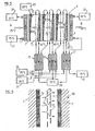
- FIG. 2 gives an exemplary diagram of the temperatures making it possible to obtain, taking into account the thermal drops through the thin exchange plates 1 and 2, an outlet fluid temperature of 45 ° C. with an inlet fluid temperature at 25 ° C.
- water as a solvent is advantageous in that the water is on the one hand an economical solvent, and on the other hand has a high heat of vaporization.
- the choice of the solvent-solution couple can be determined by local conditions of use and criteria of resistance of materials and corrosion. Additives may possibly be added to the solution to limit corrosion phenomena.
- the vapor of the film 5 2 produced is dissolved and condensed at a higher temperature, that is to say in the example illustrated at 75 ° C., in the brine film 7 2 which flows along the face opposite the next plate 9 forming a plate of condensation of the second stage EM 2 by one of its faces and evaporation plate of the third stage EM 3 by its other face.
- each stage EM 1 will be adjusted to the value corresponding substantially to the equilibrium of the vapor pressures of the water / saline solution couple at the temperatures envisaged for each stage.
- the pressure differences between the external faces 1 1 and 2 4 of the system can be easily cashed in by providing (not shown) a few spacers between the successive plates 1 1 , 8, 9, 10, 12 4 .
- the evaporator-mixers will be all the more efficient and all the less bulky as the interval between the plates facing evaporation and condensation will be reduced, so that the transfer of the vapor, illustrated by arrows 6 can be very effective. With such a device, one can reasonably expect to obtain heat transfer flux densities of the order of 20 to 30 kw / m 2 and more.
- the low level heat is supplied by the heat transfer fluid 3 to the inlet plate 1 of the first evaporator-mixer EM ,.
- the heat transfer fluid from the waste heat source enters at 13 for example at the temperature of 25 ° C and exits at 14 at the temperature of 20 ° C. This lowering of the temperature of the "cold source” is used to evaporate the film of water 5 1 in the first stage of evaporator-mixer EM,.
- the diluted solutions are collected in 20, for example around 25 ° C and will either be regenerated, or stored, or even possibly rejected according to the conditions of installation of the installation (especially if one is near the sea or large rivers accepting the discharge of dilute saline solutions).
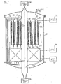
- FIG. 7 a schematic description of a three-stage evaporator-mixer exchanger in series of cylindrical type allowing the operation of the installation under high pressures and temperatures.
- the device comprises three exchanger-mixers arranged concentrically EM ,, EM z , EM 3 operating in series according to the same principle as described in the preceding figures and in particular in FIG. 5.
- exchanger-mixers are mounted inside a vertical cylindrical tank 24. Below the evaporator-mixers EMy, EM 2 , EM 3 are mounted, for example also housed in the tank 24, heat exchangers 25 which can operate as the exchangers 15, 16, 17 of FIG. 5.
- the device is essentially suitable for the revalorization of low pressure vapor condensates, in the form of liquid water which can be introduced into the installation as illustrated in 26 around 70-100 ° C. for example. Part of this water passes along arrow 27 in the center of the exchanger and heats up in contact with the last condensation wall 2 3 of the EM 3 exchanger to the maximum temperature depending on the installation, which can reach example 150 to 200 ° C. Medium pressure steam is thus recovered at 28, for example at 15 bars and 200 ° C. suitable for any industrial use.
- Another part of the water coming from the supply at 70-100 ° C. circulates according to the arrows 29 inside the enclosure 24 and is used to heat the first stages of the exchangers 25 and the first stage of the evaporator -Mixer EM 1 by its outer face 1 1 which bathes inside the envelope 24 in this ascending stream of water.
- the surplus, if any, of the water thus supplied to the apparatus can be extracted as indicated at 30 for example at a temperature between 65 and 95 ° C.
- the fresh water flowing on the outer plate 1 1 of the first stage exchanger-mixer is brought as indicated in 31 to the temperature where it is available from 70 to 100 ° C, this water being advantageously constituted by a small quantity derived from the source 26.
- the brine is brought as indicated by the arrows 32 on the face of the plate 33 communicating with the interior space of the EM exchanger 1 from a storage source 34 for example at 20 ° C. and after heating through the exchangers 25.
- the exchangers 25 are heated by the dilute brine solutions escaping from the three stages of the evaporator-mixers EM ,, EM 2 , EM 3 as indicated by the arrows 34, 35, 36 and this, at temperatures ranging from increasing to the temperature of the hottest plate 2 3 of the last EM-exchanger-mixer stage 3 .
- the diluted solutions escape from the exchangers 25 as indicated in 37 for example at around 105 ° C. They are advantageously treated at this temperature by evaporation-separation to reconstitute the brine. This evaporation-separation treatment may be carried out in devices which will be described below.
- the EM 2 and EM 3 evaporator-mixers operate similarly to the EM 1 exchanger-mixer but at higher temperatures.
- the second and third stage water film supplies were identified respectively (at increasing temperatures) and in 40, 41 the second and third stage brine supplies (at increasing temperatures) ).
- evaporator-separator device used industrially for example for the desalination of seawater.
- evaporator-separators can moreover have a structure similar or identical to that of the EM evaporator-mixers described above, but operating in some way in the opposite direction.
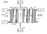
- FIG. 8 describes a system particularly well suited to the use of industrial or residential buildings.
- the exchange volume 69 closed on one side by the vaporization plate 70 will be supplied as illustrated at 68 of the first stage EM 1 of an evaporator-mixer, and on the other side by the plate 71 of condensation of an evaporator-mixer EM o .
- the evaporator-mixer EM 1 is followed by a second stage of evaporator-mixer, these two evaporator-mixers operating in series and forming a heat pump as it has been described above in particular in relation to the Figures 1 and 3.
- the outer wall 72 of the exchanger-mixer EM 2 is brought for example to 65 ° C, allowing to heat to 60 ° C the heat transfer fluid 73 ensuring the heating of the installation.
- the surface 71a has plate 71 serving as a condensing surface on which the brine flows, which makes it possible by evaporation of the film 75 of water on the outer plate 76 of the EM exchanger-mixer o to obtain refrigeration, for example 5 ° C. at 0 ° C of a coolant in contact with the outer face of the plate 76.
Landscapes
- Engineering & Computer Science (AREA)
- Physics & Mathematics (AREA)
- Mechanical Engineering (AREA)
- Thermal Sciences (AREA)
- General Engineering & Computer Science (AREA)
- Chemical & Material Sciences (AREA)
- Materials Engineering (AREA)
- Vaporization, Distillation, Condensation, Sublimation, And Cold Traps (AREA)
- Other Air-Conditioning Systems (AREA)
Claims (5)
dadurch gekennzeichnet, daß mehrere erwähnte Grundvorrichtungen in Reihe verbunden sind und daß die Kondensationsplatte der Grundvorrichtung der Stufe der Ordnung n mit ihrer anderen Fläche die Verdampfungsplatte der Grundvorrichtung der Stufe mit der Ordnung n+1 bildet.
Priority Applications (1)
| Application Number | Priority Date | Filing Date | Title |
|---|---|---|---|
| DE8585101378T DE3176997D1 (en) | 1980-08-11 | 1981-08-05 | System for the revaluation of low-level thermal energy using phenomena of evaporation, and solution of two fluids being in equilibrium of vapour pressure at different temperatures |
Applications Claiming Priority (4)
| Application Number | Priority Date | Filing Date | Title |
|---|---|---|---|
| FR8017676 | 1980-08-11 | ||
| FR8017676A FR2488379B1 (fr) | 1980-08-11 | 1980-08-11 | Procede et dispositifs pour la revalorisation d'energie thermique a bas niveau mettant en oeuvre des phenomenes d'evaporation et de melange de deux fluides en equilibre de pression de vapeur |
| FR8113846A FR2509845B2 (fr) | 1981-07-16 | 1981-07-16 | Procede et dispositifs pour la revalorisation d'energie thermique a bas niveau mettant en oeuvre des phenomenes d'evaporation et de melange de deux fluides en equilibre de pression de vapeur sous des temperatures differentes, et application a la valorisation d'une energie thermique noble |
| FR8113846 | 1981-07-16 |
Related Child Applications (1)
| Application Number | Title | Priority Date | Filing Date |
|---|---|---|---|
| EP85101378.9 Division-Into | 1985-02-08 |
Publications (3)
| Publication Number | Publication Date |
|---|---|
| EP0046112A2 EP0046112A2 (de) | 1982-02-17 |
| EP0046112A3 EP0046112A3 (en) | 1982-09-01 |
| EP0046112B1 true EP0046112B1 (de) | 1986-02-26 |
Family
ID=26221945
Family Applications (2)
| Application Number | Title | Priority Date | Filing Date |
|---|---|---|---|
| EP81401260A Expired EP0046112B1 (de) | 1980-08-11 | 1981-08-05 | Vorrichtungen und Systeme zum Aufwerten thermischer Energie mit niedrigem Niveau unter Ausnutzung der Verdampfung, und Mischung zweier strömender Medien mit gleichem Dampfdruck bei unterschiedlichen Temperaturen |
| EP85101378A Expired EP0148756B1 (de) | 1980-08-11 | 1981-08-05 | System zum Aufwertem thermischer Energie mit niedrigem Niveau unter Ausnutzung der Verdampfung, und Mischung zweier strömender Medien mit gleichem Dampfdruck bei unterschiedlichen Temperaturen |
Family Applications After (1)
| Application Number | Title | Priority Date | Filing Date |
|---|---|---|---|
| EP85101378A Expired EP0148756B1 (de) | 1980-08-11 | 1981-08-05 | System zum Aufwertem thermischer Energie mit niedrigem Niveau unter Ausnutzung der Verdampfung, und Mischung zweier strömender Medien mit gleichem Dampfdruck bei unterschiedlichen Temperaturen |
Country Status (3)
| Country | Link |
|---|---|
| US (2) | US4527621A (de) |
| EP (2) | EP0046112B1 (de) |
| DE (1) | DE3173876D1 (de) |
Families Citing this family (16)
| Publication number | Priority date | Publication date | Assignee | Title |
|---|---|---|---|---|
| GB8308137D0 (en) * | 1983-03-24 | 1983-05-05 | Ici Plc | Compression-type heat pumps |
| GB8308135D0 (en) * | 1983-03-24 | 1983-05-05 | Ici Plc | Centrifugal heat pump |
| FR2557277B1 (fr) * | 1983-12-22 | 1986-04-11 | Alsthom Atlantique | Machine a induction thermique |
| GB8400324D0 (en) * | 1984-01-06 | 1984-02-08 | Ici Plc | Heat pumps |
| US4553409A (en) * | 1984-07-12 | 1985-11-19 | Hitachi Zosen Corporation | Multiple regeneration multiple absorption type heat pump |
| FR2591504B1 (fr) * | 1985-12-13 | 1990-04-20 | Centre Nat Rech Scient | Procede d'evaporation-condensation de films ruisselants, elements pour sa mise en oeuvre et ses applications. |
| DE3833666C2 (de) * | 1988-10-04 | 1994-02-17 | Gerd Dr Ing Wilhelm | Verbundsysteme aus normaler und inverser Rektifikation |
| WO1991013301A1 (en) * | 1990-02-27 | 1991-09-05 | Cheng Chen Yen | Absorption vapor pressure enhancement process and its applications in high level refrigeration and separation processes |
| US5291942A (en) * | 1993-05-24 | 1994-03-08 | Gas Research Institute | Multiple stage sorption and desorption process and apparatus |
| FR2754594B1 (fr) * | 1996-10-10 | 1998-12-31 | Gaz De France | Frigopompe |
| FR2756621B1 (fr) * | 1996-11-29 | 1999-02-19 | Gaz De France | Thermo-frigopompe |
| FR2757255B1 (fr) * | 1996-12-13 | 1999-03-05 | Gaz De France | Dispositif a absorption de chaleur et/ou de froid multietagee |
| US6176101B1 (en) | 1997-06-18 | 2001-01-23 | Gas Research Institute | Flat-plate absorbers and evaporators for absorption coolers |
| HU0100463D0 (en) * | 2001-01-29 | 2001-03-28 | Szopko Mihaly | Method and device for absorption heat pumping |
| CA2778101A1 (en) * | 2012-05-24 | 2013-11-24 | Jean Pierre Hofman | Power generation by pressure differential |
| CN109681944A (zh) * | 2019-02-13 | 2019-04-26 | 上海虹铂环保科技有限公司 | 一种利用电空气源热水机组深度回收烟气潜化废热组合装置 |
Citations (1)
| Publication number | Priority date | Publication date | Assignee | Title |
|---|---|---|---|---|
| US2182453A (en) * | 1936-01-18 | 1939-12-05 | William H Sellew | Heat transfer process and apparatus |
Family Cites Families (22)
| Publication number | Priority date | Publication date | Assignee | Title |
|---|---|---|---|---|
| DE278076C (de) * | 1911-08-11 | |||
| US1683434A (en) * | 1924-01-09 | 1928-09-04 | Siemens Schuckertwerke Gmbh | Method of heating buildings |
| FR675258A (fr) * | 1928-05-18 | 1930-02-07 | Industrikemiska Ab | Procédé et dispositif d'évaporation |
| US1913468A (en) * | 1930-01-09 | 1933-06-13 | Hoover Co | Arrangement for reducing the transmission of heat |
| GB372339A (en) * | 1930-01-09 | 1932-05-02 | Siemens Ag | Utilizing absorption refrigerating machines for heat insulating purposes |
| GB422150A (en) * | 1932-12-21 | 1935-01-07 | Siemens Ag | Improvements relating to heat converters comprising absorption apparatus |
| US2162607A (en) * | 1935-11-20 | 1939-06-13 | American Mach & Foundry | Supply of material in wrapping machines |
| FR840283A (fr) * | 1937-07-06 | 1939-04-21 | Perfectionnements apportés aux machines frigorifiques fonctionnant par l'affinité d'un fluide, telque la vapeur d'eau, pour d'autres substances | |
| FR1056314A (fr) * | 1952-02-15 | 1954-02-25 | Procédé et dispositifs concernant les machines frigorifiques à absorption | |
| US3306346A (en) * | 1962-12-03 | 1967-02-28 | Donald F Othmer | Method for cooling volatile liquids |
| DE1444337A1 (de) * | 1963-11-13 | 1968-11-28 | Forsch Ges Verfahrenstechnik E | Verdampfer |
| US3483710A (en) * | 1968-06-13 | 1969-12-16 | Crane Co | Cascade absorption refrigeration system |
| US3822192A (en) * | 1971-12-08 | 1974-07-02 | Aluminum Co Of America | Evaporative method |
| DE2219083C3 (de) * | 1972-04-19 | 1979-08-09 | Doneckij Filial Vnipitschermetenergootschistka, Donezk (Sowjetunion) | Absorptionskälteanlage |
| FR2274564A1 (fr) * | 1974-06-17 | 1976-01-09 | Rigollot Georges | Installation pour la distillation de grandes quantites d'eau |
| US4009575A (en) * | 1975-05-12 | 1977-03-01 | said Thomas L. Hartman, Jr. | Multi-use absorption/regeneration power cycle |
| DE2552538A1 (de) * | 1975-11-22 | 1977-05-26 | Hans Dipl Ing Dr Herrmann | Heizofen mit waermepumpe |
| DE2648855A1 (de) * | 1976-10-25 | 1978-04-27 | Herbst Donald | Einrichtung zur senkung der durch rauchgase bedingten waermeverluste bei einem mit oel oder gas betriebenen heizkessel |
| DE2743488A1 (de) * | 1977-09-28 | 1979-03-29 | Karl Friedrich Prof Dr Knoche | Verfahren und vorrichtung zur nutzung von sonnenenergie fuer raumheizung |
| US4223535A (en) * | 1978-12-22 | 1980-09-23 | Kumm Emerson L | Absorption solar powered air conditioning system with storage capacity |
| DE2939423A1 (de) * | 1979-09-28 | 1981-04-16 | Alefeld, Georg, Prof.Dr., 8000 München | Verfahren zum betrieb einer eine absorber-waermepumpe enthaltenden heizungsanlage und heizungsanlage zur durchfuehrung dieses verfahrens |
| DE3169318D1 (en) * | 1980-03-17 | 1985-04-25 | Hitachi Ltd | System for heat energy conversion |
-
1981
- 1981-08-05 EP EP81401260A patent/EP0046112B1/de not_active Expired
- 1981-08-05 EP EP85101378A patent/EP0148756B1/de not_active Expired
- 1981-08-05 DE DE8181401260T patent/DE3173876D1/de not_active Expired
- 1981-08-07 US US06/291,145 patent/US4527621A/en not_active Expired - Fee Related
-
1984
- 1984-11-29 US US06/658,843 patent/US4606404A/en not_active Expired - Fee Related
Patent Citations (1)
| Publication number | Priority date | Publication date | Assignee | Title |
|---|---|---|---|---|
| US2182453A (en) * | 1936-01-18 | 1939-12-05 | William H Sellew | Heat transfer process and apparatus |
Also Published As
| Publication number | Publication date |
|---|---|
| US4606404A (en) | 1986-08-19 |
| EP0148756B1 (de) | 1989-03-08 |
| DE3173876D1 (en) | 1986-04-03 |
| EP0148756A2 (de) | 1985-07-17 |
| EP0046112A2 (de) | 1982-02-17 |
| EP0148756A3 (en) | 1986-04-23 |
| US4527621A (en) | 1985-07-09 |
| EP0046112A3 (en) | 1982-09-01 |
Similar Documents
| Publication | Publication Date | Title |
|---|---|---|
| EP0046112B1 (de) | Vorrichtungen und Systeme zum Aufwerten thermischer Energie mit niedrigem Niveau unter Ausnutzung der Verdampfung, und Mischung zweier strömender Medien mit gleichem Dampfdruck bei unterschiedlichen Temperaturen | |
| US20040113291A1 (en) | Diffusion driven desalination apparatus and process | |
| EP1636138A2 (de) | Verfahren und vorrichtung zur destilliation insbesondere zur herstellung von süsswasser | |
| FR2471562A1 (fr) | Dispositif modulaire pour effectuer un chauffage ou un refroidissement a partir de l'energie solaire par un cycle intermittent de pompe a chaleur a adsorption, et appareil compose de tels dispositifs | |
| WO2001096244A1 (fr) | Procedes et appareils de distillation notamment pour produire de l'eau douce | |
| EP3096851A1 (de) | Anlage und verfahren zur aufbereitung von in eine natürliche umgebung gepumptem wasser durch verdampfung/kondensation | |
| US10926223B2 (en) | Apparatus for solar-assisted water distillation using waste heat of air conditioners | |
| EP0072305B1 (de) | Verfahren zum Speichern von mechanischer oder thermischer Energie in Form von chemischer Energie und zur wenigstens teilweisen Rückgewinnung der gespeicherten Energie und Vorrichtung zur Durchführung des Verfahrens | |
| FR2531418A1 (fr) | Procede et appareil de distillation de saumure pour l'obtention d'eau douce | |
| BE1024466B1 (fr) | Unité de dessalement d'eau par compression mécanique de vapeur | |
| US8202402B2 (en) | System and method of passive liquid purification | |
| EP2354710A1 (de) | Vorrichtung und Verfahren zur Wärmerückgewinnung im Rauchgakanal eines Wärmekraftwerks | |
| FR2488379A1 (fr) | Procede et dispositifs pour la revalorisation d'energie thermique a bas niveau mettant en oeuvre des phenomenes d'evaporation et de melange de deux fluides en equilibre de pression de vapeur | |
| US20120267231A1 (en) | System and method of passive liquid purification | |
| Stefano et al. | Setting up of a cost-effective continuous desalination plant based on coupling solar and geothermal energy | |
| EP0007835A1 (de) | Verfahren zum Trennen eines Gases und eines kondensierbaren Dampfes und seine Anwendungen | |
| FR2591504A1 (fr) | Procede d'evaporation-condensation de films ruisselants, elements pour sa mise en oeuvre et ses applications. | |
| EP3502577B1 (de) | Luftaufbereitungssystem, das eine vorrichtung zur absorption umfasst, und entsprechendes verfahren | |
| FR2468085A1 (fr) | Appareil frigorifique a sorption, procede pour la mise en service de cet appareil et utilisation de ce dernier | |
| FR2922001A1 (fr) | Installation de chauffage pour la production d'eau chaude sanitaire et d'eau chaude de chauffage,et dispositif utilise dans une telle installation de chauffage. | |
| FR2586091A1 (fr) | Dispositif d'echange de chaleur parcouru par deux fluides a circuits independants | |
| FR2754594A1 (fr) | Frigopompe | |
| WO2007144024A1 (fr) | Dispositif a echanges thermiques | |
| FR2524335A1 (fr) | Distillateur a effets multiples, utilisable notamment pour le dessalement de l'eau de mer et des eaux saumatres au moyen d'energie renouvelable | |
| FR2529651A1 (fr) | Production de froid et/ou de chaleur par utilisation de reactions electrochimiques |
Legal Events
| Date | Code | Title | Description |
|---|---|---|---|
| PUAI | Public reference made under article 153(3) epc to a published international application that has entered the european phase |
Free format text: ORIGINAL CODE: 0009012 |
|
| AK | Designated contracting states |
Designated state(s): BE DE GB LU NL SE |
|
| PUAL | Search report despatched |
Free format text: ORIGINAL CODE: 0009013 |
|
| AK | Designated contracting states |
Designated state(s): BE DE GB LU NL SE |
|
| 17P | Request for examination filed |
Effective date: 19820630 |
|
| GRAA | (expected) grant |
Free format text: ORIGINAL CODE: 0009210 |
|
| AK | Designated contracting states |
Designated state(s): BE DE GB LU NL SE |
|
| REF | Corresponds to: |
Ref document number: 3173876 Country of ref document: DE Date of ref document: 19860403 |
|
| BECN | Be: change of holder's name |
Effective date: 19860226 |
|
| PLBE | No opposition filed within time limit |
Free format text: ORIGINAL CODE: 0009261 |
|
| STAA | Information on the status of an ep patent application or granted ep patent |
Free format text: STATUS: NO OPPOSITION FILED WITHIN TIME LIMIT |
|
| 26N | No opposition filed | ||
| RAP2 | Party data changed (patent owner data changed or rights of a patent transferred) |
Owner name: ETABLISSEMENT PUBLIC DIT: CENTRE NATIONAL DE LA R |
|
| PGFP | Annual fee paid to national office [announced via postgrant information from national office to epo] |
Ref country code: SE Payment date: 19910717 Year of fee payment: 11 Ref country code: LU Payment date: 19910717 Year of fee payment: 11 |
|
| PGFP | Annual fee paid to national office [announced via postgrant information from national office to epo] |
Ref country code: GB Payment date: 19910730 Year of fee payment: 11 |
|
| PGFP | Annual fee paid to national office [announced via postgrant information from national office to epo] |
Ref country code: BE Payment date: 19910801 Year of fee payment: 11 |
|
| PGFP | Annual fee paid to national office [announced via postgrant information from national office to epo] |
Ref country code: NL Payment date: 19910831 Year of fee payment: 11 |
|
| PGFP | Annual fee paid to national office [announced via postgrant information from national office to epo] |
Ref country code: DE Payment date: 19910925 Year of fee payment: 11 |
|
| EPTA | Lu: last paid annual fee | ||
| PG25 | Lapsed in a contracting state [announced via postgrant information from national office to epo] |
Ref country code: LU Free format text: LAPSE BECAUSE OF NON-PAYMENT OF DUE FEES Effective date: 19920805 Ref country code: GB Effective date: 19920805 |
|
| PG25 | Lapsed in a contracting state [announced via postgrant information from national office to epo] |
Ref country code: SE Effective date: 19920806 |
|
| PG25 | Lapsed in a contracting state [announced via postgrant information from national office to epo] |
Ref country code: BE Effective date: 19920831 |
|
| BERE | Be: lapsed |
Owner name: CENTRE NATIONAL DE LA RECHERCHE SCIENTIFIQUE CNRS Effective date: 19920831 |
|
| PG25 | Lapsed in a contracting state [announced via postgrant information from national office to epo] |
Ref country code: NL Effective date: 19930301 |
|
| GBPC | Gb: european patent ceased through non-payment of renewal fee |
Effective date: 19920805 |
|
| PG25 | Lapsed in a contracting state [announced via postgrant information from national office to epo] |
Ref country code: DE Effective date: 19930501 |
|
| EUG | Se: european patent has lapsed |
Ref document number: 81401260.5 Effective date: 19930307 |