EP0046112B1 - Device and systems for the revaluation of low-level thermal energy using phenomena of evaporation, and solution of two fluids being in equilibrium of vapour pressure at different temperatures - Google Patents
Device and systems for the revaluation of low-level thermal energy using phenomena of evaporation, and solution of two fluids being in equilibrium of vapour pressure at different temperatures Download PDFInfo
- Publication number
- EP0046112B1 EP0046112B1 EP81401260A EP81401260A EP0046112B1 EP 0046112 B1 EP0046112 B1 EP 0046112B1 EP 81401260 A EP81401260 A EP 81401260A EP 81401260 A EP81401260 A EP 81401260A EP 0046112 B1 EP0046112 B1 EP 0046112B1
- Authority
- EP
- European Patent Office
- Prior art keywords
- temperature
- source
- heat
- evaporation
- liquid
- Prior art date
- Legal status (The legal status is an assumption and is not a legal conclusion. Google has not performed a legal analysis and makes no representation as to the accuracy of the status listed.)
- Expired
Links
Images

Classifications
-
- F—MECHANICAL ENGINEERING; LIGHTING; HEATING; WEAPONS; BLASTING
- F25—REFRIGERATION OR COOLING; COMBINED HEATING AND REFRIGERATION SYSTEMS; HEAT PUMP SYSTEMS; MANUFACTURE OR STORAGE OF ICE; LIQUEFACTION SOLIDIFICATION OF GASES
- F25B—REFRIGERATION MACHINES, PLANTS OR SYSTEMS; COMBINED HEATING AND REFRIGERATION SYSTEMS; HEAT PUMP SYSTEMS
- F25B30/00—Heat pumps
- F25B30/04—Heat pumps of the sorption type
-
- F—MECHANICAL ENGINEERING; LIGHTING; HEATING; WEAPONS; BLASTING
- F25—REFRIGERATION OR COOLING; COMBINED HEATING AND REFRIGERATION SYSTEMS; HEAT PUMP SYSTEMS; MANUFACTURE OR STORAGE OF ICE; LIQUEFACTION SOLIDIFICATION OF GASES
- F25B—REFRIGERATION MACHINES, PLANTS OR SYSTEMS; COMBINED HEATING AND REFRIGERATION SYSTEMS; HEAT PUMP SYSTEMS
- F25B15/00—Sorption machines, plants or systems, operating continuously, e.g. absorption type
- F25B15/02—Sorption machines, plants or systems, operating continuously, e.g. absorption type without inert gas
- F25B15/06—Sorption machines, plants or systems, operating continuously, e.g. absorption type without inert gas the refrigerant being water vapour evaporated from a salt solution, e.g. lithium bromide
-
- Y—GENERAL TAGGING OF NEW TECHNOLOGICAL DEVELOPMENTS; GENERAL TAGGING OF CROSS-SECTIONAL TECHNOLOGIES SPANNING OVER SEVERAL SECTIONS OF THE IPC; TECHNICAL SUBJECTS COVERED BY FORMER USPC CROSS-REFERENCE ART COLLECTIONS [XRACs] AND DIGESTS
- Y02—TECHNOLOGIES OR APPLICATIONS FOR MITIGATION OR ADAPTATION AGAINST CLIMATE CHANGE
- Y02A—TECHNOLOGIES FOR ADAPTATION TO CLIMATE CHANGE
- Y02A30/00—Adapting or protecting infrastructure or their operation
- Y02A30/27—Relating to heating, ventilation or air conditioning [HVAC] technologies
-
- Y—GENERAL TAGGING OF NEW TECHNOLOGICAL DEVELOPMENTS; GENERAL TAGGING OF CROSS-SECTIONAL TECHNOLOGIES SPANNING OVER SEVERAL SECTIONS OF THE IPC; TECHNICAL SUBJECTS COVERED BY FORMER USPC CROSS-REFERENCE ART COLLECTIONS [XRACs] AND DIGESTS
- Y02—TECHNOLOGIES OR APPLICATIONS FOR MITIGATION OR ADAPTATION AGAINST CLIMATE CHANGE
- Y02B—CLIMATE CHANGE MITIGATION TECHNOLOGIES RELATED TO BUILDINGS, e.g. HOUSING, HOUSE APPLIANCES OR RELATED END-USER APPLICATIONS
- Y02B30/00—Energy efficient heating, ventilation or air conditioning [HVAC]
- Y02B30/62—Absorption based systems
Definitions
- the subject of the present invention is a device and systems for upgrading and storing thermal energy at a low level using evaporation and mixing phenomena of two fluids in vapor pressure equilibrium under different temperatures.
- a flask containing pure water and a flask containing a solution in water of a salt such as lithium chloride, calcium chloride or a substance such as soda, sulfuric acid, ammonia gas are in vapor equilibrium only at different temperatures.
- the vapor pressure of pure water at 20 ° C is substantially equal to that of a saturated brine of calcium chloride at 50 ° C and that of a saturated solution of lithium chloride at 70- 80 ° C or a solution of sulfuric acid, soda or zinc chloride around 120 ° C.
- the concentrated solution will be called “brine” and the diluted solution resulting from the mixture of the concentrated solution and the solvent will be called “dilute”.
- the concentrated solution could possibly go so far as to be pure solute.
- the system For the system to operate continuously, it must be continuously supplied or regenerated with the solvent (water for example) and the solute (salt or other body: calcium chloride for example) necessary for the operation.
- solvent water for example
- solute salt or other body: calcium chloride for example
- the noble energy necessary for the operation of the pump is provided by the dilution effect of a certain amount of solute in solvent.
- the invention provides a device and one of. new and original systems allowing in particular an effective and very economic revaluation of thermal energy at low level particularly well adapted to the heating of buildings.
- the invention also allows a particularly elegant and efficient upgrading of low level thermal discharges of all kinds, such as thermal discharges from nuclear power plants or others, thermal discharges from factories, waste water, etc.
- the invention also allows the long-term recovery and storage of diluted and intermittent energies such as solar energy and cold wind energy.
- the invention also makes it possible to use the "ambient" energy of water bodies such as river, lake and sea water, and water of geothermal origin.
- the patent GB-A-372,339 essentially describes an absorption refrigeration machine using, as a cooling source, an air condenser at room temperature.
- a generator for example electric or gas, allows the regeneration of an absorption solution which is used inside a volume thermally insulated from the outside to favor the evaporation of a refrigerant solution to vaporize which will dilute the absorption solution and will borrow its heat of vaporization from the interior wall of the chamber to be cooled.
- heat exchanges between the walls with regard to evaporation and condensation are avoided in this installation as far as possible, possibly by providing thermal insulation of cork or the like and, in addition, the volume in which the vaporization of the fluid takes place is filled.
- refrigerant of a neutral gas such as air or rare gas reducing heat exchanges.
- the evaporating surfaces of the refrigerant to be vaporized and of absorption are arranged at relatively close distances, the best compromise having to be found to reduce the heat exchange between the two facing surfaces while not lengthening the path too much vapors to condense.
- the patent also provides for the operation of the installation in the opposite direction by reversing the circuits.
- the installation does not provide or allow heating from the service water of a higher temperature fluid.
- the structure described does not allow a direct thermal exchange between the liquids to be refrigerated and of service and the condensable vapor medium by interposition of a single metallic separating surface.
- the structure does not lend itself to stacking several identical structures making it possible to obtain, for the water to be refrigerated in successive stages, temperatures which are increasingly different from the service temperature.
- German patent application DE-A-1444337 describes an evaporator comprising several evaporation-condensation chambers mounted stacked in series and working under decreasing temperatures and pressures. There is no question in this document of extracting heat from a lower level source.
- Said device being characterized in that several elementary devices mentioned are associated in series, the condensation plate. of the elementary device of the stage of rank n constituting by its other face the vaporization plate of the elementary device of the stage of rank n + 1.
- Figure 1 illustrates a device forming an evaporator-melan geur used within the framework of the invention identified as a whole EM, making it possible to transfer a quantity of heat Q borrowed from a low level thermal source called "cold source” to a second source at higher temperature called “hot source”.
- the evaporator-mixer device makes it possible to transfer a quantity of heat Q available at a determined temperature, for example 25 ° C. brought to one face of a first plate 1 of the device and to release it after passing through the device. on one side of a second plate 2 at a higher temperature, for example 45 ° C.
- the heat source available at low level consists of a stream of fluid, for example waste water substantially at the temperature of the "cold source", brought by a pipe 3 in exchange for heat. with an outer face 1A of the plate 1 of the device.
- the heat is taken from the device at the temperature of the "hot source” by a heat transfer fluid, such as, for example, water supplied by a conduit 4 in exchange for heat with the external face 2A of the plate 2 of the device.
- a heat transfer fluid such as, for example, water supplied by a conduit 4 in exchange for heat with the external face 2A of the plate 2 of the device.
- the transfer of heat from plate 1 to plate 2 and the increase in the thermal level of the transferred heat is effected by the evaporation of a film of a fluid (solvent), such as for example water.
- a fluid such as for example water.
- soft 5 which flows downward along the inner face 1B of the plate 1 heated by the fluid 3 constituting the low-level heat source available, and by the condensation of the vapor produced, the transfer of which is shown diagrammatically by the arrows 6, on the internal face 2B of the plate 2 in admixture with a second fluid or a saturated solution of a solute (brine) flowing in a film wetting the face 2B of the plate 2.
- the thermal example shown corresponds to the use for film 5 of a fresh water film and for film 7 of a substantially saturated solution of calcium chloride in water.
- FIG. 2 gives an exemplary diagram of the temperatures making it possible to obtain, taking into account the thermal drops through the thin exchange plates 1 and 2, an outlet fluid temperature of 45 ° C. with an inlet fluid temperature at 25 ° C.
- water as a solvent is advantageous in that the water is on the one hand an economical solvent, and on the other hand has a high heat of vaporization.
- the choice of the solvent-solution couple can be determined by local conditions of use and criteria of resistance of materials and corrosion. Additives may possibly be added to the solution to limit corrosion phenomena.
- the vapor of the film 5 2 produced is dissolved and condensed at a higher temperature, that is to say in the example illustrated at 75 ° C., in the brine film 7 2 which flows along the face opposite the next plate 9 forming a plate of condensation of the second stage EM 2 by one of its faces and evaporation plate of the third stage EM 3 by its other face.
- each stage EM 1 will be adjusted to the value corresponding substantially to the equilibrium of the vapor pressures of the water / saline solution couple at the temperatures envisaged for each stage.
- the pressure differences between the external faces 1 1 and 2 4 of the system can be easily cashed in by providing (not shown) a few spacers between the successive plates 1 1 , 8, 9, 10, 12 4 .
- the evaporator-mixers will be all the more efficient and all the less bulky as the interval between the plates facing evaporation and condensation will be reduced, so that the transfer of the vapor, illustrated by arrows 6 can be very effective. With such a device, one can reasonably expect to obtain heat transfer flux densities of the order of 20 to 30 kw / m 2 and more.
- the low level heat is supplied by the heat transfer fluid 3 to the inlet plate 1 of the first evaporator-mixer EM ,.
- the heat transfer fluid from the waste heat source enters at 13 for example at the temperature of 25 ° C and exits at 14 at the temperature of 20 ° C. This lowering of the temperature of the "cold source” is used to evaporate the film of water 5 1 in the first stage of evaporator-mixer EM,.
- the diluted solutions are collected in 20, for example around 25 ° C and will either be regenerated, or stored, or even possibly rejected according to the conditions of installation of the installation (especially if one is near the sea or large rivers accepting the discharge of dilute saline solutions).
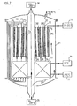
- FIG. 7 a schematic description of a three-stage evaporator-mixer exchanger in series of cylindrical type allowing the operation of the installation under high pressures and temperatures.
- the device comprises three exchanger-mixers arranged concentrically EM ,, EM z , EM 3 operating in series according to the same principle as described in the preceding figures and in particular in FIG. 5.
- exchanger-mixers are mounted inside a vertical cylindrical tank 24. Below the evaporator-mixers EMy, EM 2 , EM 3 are mounted, for example also housed in the tank 24, heat exchangers 25 which can operate as the exchangers 15, 16, 17 of FIG. 5.
- the device is essentially suitable for the revalorization of low pressure vapor condensates, in the form of liquid water which can be introduced into the installation as illustrated in 26 around 70-100 ° C. for example. Part of this water passes along arrow 27 in the center of the exchanger and heats up in contact with the last condensation wall 2 3 of the EM 3 exchanger to the maximum temperature depending on the installation, which can reach example 150 to 200 ° C. Medium pressure steam is thus recovered at 28, for example at 15 bars and 200 ° C. suitable for any industrial use.
- Another part of the water coming from the supply at 70-100 ° C. circulates according to the arrows 29 inside the enclosure 24 and is used to heat the first stages of the exchangers 25 and the first stage of the evaporator -Mixer EM 1 by its outer face 1 1 which bathes inside the envelope 24 in this ascending stream of water.
- the surplus, if any, of the water thus supplied to the apparatus can be extracted as indicated at 30 for example at a temperature between 65 and 95 ° C.
- the fresh water flowing on the outer plate 1 1 of the first stage exchanger-mixer is brought as indicated in 31 to the temperature where it is available from 70 to 100 ° C, this water being advantageously constituted by a small quantity derived from the source 26.
- the brine is brought as indicated by the arrows 32 on the face of the plate 33 communicating with the interior space of the EM exchanger 1 from a storage source 34 for example at 20 ° C. and after heating through the exchangers 25.
- the exchangers 25 are heated by the dilute brine solutions escaping from the three stages of the evaporator-mixers EM ,, EM 2 , EM 3 as indicated by the arrows 34, 35, 36 and this, at temperatures ranging from increasing to the temperature of the hottest plate 2 3 of the last EM-exchanger-mixer stage 3 .
- the diluted solutions escape from the exchangers 25 as indicated in 37 for example at around 105 ° C. They are advantageously treated at this temperature by evaporation-separation to reconstitute the brine. This evaporation-separation treatment may be carried out in devices which will be described below.
- the EM 2 and EM 3 evaporator-mixers operate similarly to the EM 1 exchanger-mixer but at higher temperatures.
- the second and third stage water film supplies were identified respectively (at increasing temperatures) and in 40, 41 the second and third stage brine supplies (at increasing temperatures) ).
- evaporator-separator device used industrially for example for the desalination of seawater.
- evaporator-separators can moreover have a structure similar or identical to that of the EM evaporator-mixers described above, but operating in some way in the opposite direction.
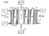
- FIG. 8 describes a system particularly well suited to the use of industrial or residential buildings.
- the exchange volume 69 closed on one side by the vaporization plate 70 will be supplied as illustrated at 68 of the first stage EM 1 of an evaporator-mixer, and on the other side by the plate 71 of condensation of an evaporator-mixer EM o .
- the evaporator-mixer EM 1 is followed by a second stage of evaporator-mixer, these two evaporator-mixers operating in series and forming a heat pump as it has been described above in particular in relation to the Figures 1 and 3.
- the outer wall 72 of the exchanger-mixer EM 2 is brought for example to 65 ° C, allowing to heat to 60 ° C the heat transfer fluid 73 ensuring the heating of the installation.
- the surface 71a has plate 71 serving as a condensing surface on which the brine flows, which makes it possible by evaporation of the film 75 of water on the outer plate 76 of the EM exchanger-mixer o to obtain refrigeration, for example 5 ° C. at 0 ° C of a coolant in contact with the outer face of the plate 76.
Description
La présente invention a pour objet un dispositif et des systèmes permettant la revalorisation et le stockage d'énergie thermique à bas niveau mettant en oeuvre des phénomènes d'évaporation et de mélange de deux fluides en équilibre de pression de vapeur sous des températures différentes.The subject of the present invention is a device and systems for upgrading and storing thermal energy at a low level using evaporation and mixing phenomena of two fluids in vapor pressure equilibrium under different temperatures.
On sait que deux fluides de nature différente peuvent être en équilibre de pression de vapeur sous des températures différentes. Ainsi par exemple, un ballon contenant de l'eau pure et un ballon contenant une solution dans l'eau d'un sel tel que chlorure de lithium, chlorure de calcium ou d'une substance telle que soude, acide sulfurique, gaz ammoniac, ne sont en équilibre de vapeur qu'à des températures différentes. Ainsi, par exemple, la pression de vapeur de l'eau pure à 20°C est sensiblement égale à celle d'une saumure saturée de chlorure de calcium à 50°C et celle d'une solution saturée de chlorure de lithium à 70-80°C ou d'une solution d'acide sulfurique, de soude ou de chlorure de zinc vers 120°C.It is known that two fluids of different nature can be in vapor pressure equilibrium under different temperatures. For example, a flask containing pure water and a flask containing a solution in water of a salt such as lithium chloride, calcium chloride or a substance such as soda, sulfuric acid, ammonia gas, are in vapor equilibrium only at different temperatures. Thus, for example, the vapor pressure of pure water at 20 ° C is substantially equal to that of a saturated brine of calcium chloride at 50 ° C and that of a saturated solution of lithium chloride at 70- 80 ° C or a solution of sulfuric acid, soda or zinc chloride around 120 ° C.
Il est possible de mettre à profit ce phénomène pour faire "bouillir" à basse température un liquide que l'on appellera "solvant" tel que de l'eau, en utilisant comme condenseur un volume dans lequel est maintenu à température plus élevée un mélange formé par dissolution dans le solvant d'un autre corps, que l'on appellera "soluté", qui a la propriété d'abaisser la pression de vapeur du solvant. On peut faire travailler la vapeur dans une 'turbine. On peut également mettre à profit la différence de températures des solutions pour lesquelles il y a équilibre de vapeur pour transférer des calories apportées à bas niveau au solvant liquide et les récupérer à un niveau plus élevé, c'est-à-dire une température plus élevée, dans la solution obtenue par mélange, l'énergie "noble" nécessaire étant apportée par l'augmentation d'entropie du système lors du mélange du solvant à la solution concentrée de soluté pour former une solution diluée. Par abréviation, la solution concentrée sera appelée "saumure" et la solution diluée résultant du mélange de la solution concentrée et du solvant sera appelée "diluat". La solution concentrée pourra éventuellement aller jusqu'à être du soluté pur.It is possible to take advantage of this phenomenon to “boil” at low temperature a liquid which will be called “solvent” such as water, by using as a condenser a volume in which a mixture is kept at higher temperature. formed by dissolution in the solvent of another body, which will be called "solute", which has the property of lowering the vapor pressure of the solvent. Steam can be work in a turbine. One can also take advantage of the temperature difference of the solutions for which there is vapor equilibrium to transfer calories brought in at low level to the liquid solvent and recover them at a higher level, i.e. a higher temperature. high, in the solution obtained by mixing, the "noble" energy required being provided by the increase in entropy of the system when mixing the solvent with the concentrated solution of solute to form a dilute solution. By abbreviation, the concentrated solution will be called "brine" and the diluted solution resulting from the mixture of the concentrated solution and the solvent will be called "dilute". The concentrated solution could possibly go so far as to be pure solute.
Pour que le système fonctionne de façon continue, il faut lui apporter ou régénérer en permanence le solvant (eau par exemple) et le soluté (sel ou autre corps: chlorure de calcium par exemple) nécessaires à l'opération.For the system to operate continuously, it must be continuously supplied or regenerated with the solvent (water for example) and the solute (salt or other body: calcium chloride for example) necessary for the operation.
Il s'agit en somme d'une "pompe à chaieur": l'énergie noble nécessaire au fonctionnement de la pompe est fourni par l'effet de dilution d'une certaine quantité de soluté dans du solvant.It is basically a "heat pump": the noble energy necessary for the operation of the pump is provided by the dilution effect of a certain amount of solute in solvent.
L'invention propose dispositif et un des . systèmes nouveaux et originaux permettant notamment une revalorisation effective et très économique d'énergie thermique à bas niveau particulièrement bien adaptée au chauffage des bâtiments.The invention provides a device and one of. new and original systems allowing in particular an effective and very economic revaluation of thermal energy at low level particularly well adapted to the heating of buildings.
L'invention permet également une revalorisation particulièrement élégante et efficace des rejets thermiques à bas niveau de toutes natures, tels que rejets thermiques de centrales nucléaires ou autres, rejets thermiques d'usines, eaux usées, etc. L'invention permet également la valorisation et le stockage de longue durée d'énergies diluées et intermittentes telles que l'énergie solaire et l'énergie du vent froid.The invention also allows a particularly elegant and efficient upgrading of low level thermal discharges of all kinds, such as thermal discharges from nuclear power plants or others, thermal discharges from factories, waste water, etc. The invention also allows the long-term recovery and storage of diluted and intermittent energies such as solar energy and cold wind energy.
L'invention permet également d'utiliser l'énergie "ambiante" des masses d'eau telles que eaux de rivières, lacs et mers, et eaux d'origine géothermique.The invention also makes it possible to use the "ambient" energy of water bodies such as river, lake and sea water, and water of geothermal origin.
On connait des machines frigorifiques à absorption et également des pompes à chaleur utilisant des phénomènes d'évaporation et de condensation de deux fluides en équilibre de pression à des températures différentes.We know absorption refrigeration machines and also heat pumps using evaporation and condensation phenomena of two fluids in pressure equilibrium at different temperatures.
Le brevet GB-A-372.339 décrit essentiellement une machine frigorifique à absorption utilisant somme source de refroidissement un condenseur à air à la température ambiante. Un générateur par exemple électrique ou à gaz permet la régénération d'une solution d'absorption laquelle est utilisée à l'intérieur d'un volume thermiquement isolé de l'extérieur pour favoriser l'évaporation d'une solution frigorigène à vaporiser qui diluera la solution d'absorption et empruntera sa chaleur de vaporisation à la paroi intérieure de la chambre à refroidir. On évite autant que faire se peut dans cette installation les échanges thermiques entre les parois en regard d'évaporation et de condensation en prévoyant éventuellement une isolation thermique de liège ou autre et en outre on remplit le volume dans lequel s'effectue la vaporisation du fluide frigorigène d'un gaz neutre tel qu'air ou gaz rare réduisant les échanges thermiques.The patent GB-A-372,339 essentially describes an absorption refrigeration machine using, as a cooling source, an air condenser at room temperature. A generator, for example electric or gas, allows the regeneration of an absorption solution which is used inside a volume thermally insulated from the outside to favor the evaporation of a refrigerant solution to vaporize which will dilute the absorption solution and will borrow its heat of vaporization from the interior wall of the chamber to be cooled. In this installation, heat exchanges between the walls with regard to evaporation and condensation are avoided in this installation as far as possible, possibly by providing thermal insulation of cork or the like and, in addition, the volume in which the vaporization of the fluid takes place is filled. refrigerant of a neutral gas such as air or rare gas reducing heat exchanges.
Les surfaces d'évaporation de la solution frigorigène à vaporiser et d'absorption sont disposées à des distances relativement proches, le meilleur compromis devant être trouvé pour réduire les échanges de chaleur entre les deux surfaces en regard tout en n'allongeant pas trop le trajet des vapeurs devant se condenser.The evaporating surfaces of the refrigerant to be vaporized and of absorption are arranged at relatively close distances, the best compromise having to be found to reduce the heat exchange between the two facing surfaces while not lengthening the path too much vapors to condense.
Le brevet prévoit en outre le fonctionnement de l'installation en sens inverse par inversion des circuits.The patent also provides for the operation of the installation in the opposite direction by reversing the circuits.
Selon le brevet FR-A-1.056.314 il est décrit une machine frigorifique à absorption utilisant comme source de refroidissement une eau de service vers 25°C qui sera rejetée de l'installation à une température plus élevée. L'installation utilise en outre un bouilleur à brûleur permettant la régénération d'une solution de saumure laquelle est utilisée dans une enceinte pour favoriser l'évaporation d'eau pulvérisée dans cette enceinte sous pression et température réduites en vue de refroidir un circuit d'eau à réfrigérer vers 5°C. L'installation utilise la juxtaposition dans l'enceinte de plusieurs nappes de tubes en parallèle habillés de tôles protectrice sur lesquelles ruissellent en alternance un film d'eau frigorigène et un film de saumure d'absorption, les nappes de tubes étant parcourues respectivement par l'eau à refroidir et par l'eau de service.According to patent FR-A-1,056,314 there is described an absorption refrigeration machine using as cooling source service water at around 25 ° C. which will be discharged from the installation at a higher temperature. The installation also uses a burner boiler allowing the regeneration of a brine solution which is used in an enclosure to promote the evaporation of water sprayed into this enclosure under reduced pressure and temperature in order to cool a circuit. water to be refrigerated at around 5 ° C. The installation uses the juxtaposition in the enclosure of several layers of tubes in parallel dressed with protective sheets on which an alternating film of refrigerant water and a film of absorption brine flow, the layers of tubes being traversed respectively by the water to be cooled and by the service water.
L'installation ne prévoit ni ne permet le chauffage à partir de l'eau de service d'un fluide à température plus élevée. La structure décrite ne permet pas un échange direct thermique entre les liquides à réfrigérer et de service et le milieu de vapeur condensable par interposition d'une seule surface métallique séparatrice. En outre, la structure ne se prête pas à un empilage de plusieurs structures identiques permettant d'obtenir pour l'eau à réfrigérer par paliers succesifs des températures de plus en plus différentes de la température de service.The installation does not provide or allow heating from the service water of a higher temperature fluid. The structure described does not allow a direct thermal exchange between the liquids to be refrigerated and of service and the condensable vapor medium by interposition of a single metallic separating surface. In addition, the structure does not lend itself to stacking several identical structures making it possible to obtain, for the water to be refrigerated in successive stages, temperatures which are increasingly different from the service temperature.
La demande de brevet allemand DE-A-1444337 décrit un évaporateur comprenant plusieurs chambres d'évaporation-condensation montées empilées en série et travaillant sous des températures et pressions décroissantes. Il n'est pas question dans ce document d'extraire de la chaleur à une source à plus bas niveau.German patent application DE-A-1444337 describes an evaporator comprising several evaporation-condensation chambers mounted stacked in series and working under decreasing temperatures and pressures. There is no question in this document of extracting heat from a lower level source.
L'invention concerne essentiellement un dispositif évaporateur-mélangeur pour la revalorisation d'énergie thermique à bas niveau utilisant le transfert d'énergie d'une première source à température donnée dite "source froide" vers une deuxième source à température plus élevée dite "source chaude" par évaporation d'un premier liquide porté à la température de la "source froide" et condensation de la vapeur dudit premier liquide qui se mélange avec un deuxième. Liquide à la température de la "source chaude", lesdits premier et deuxième liquides ayant à la même température des pressions de vapeur différentes, ledit dispositif étant du type comprenant un dispositif élémentaire constitué:
- -d'une surface d'évaporation telle qu'une plaque ou analogue d'échange thermique qui est en contact, par sa face extérieure avec le fluide caloporteur de la source d'énergie à bas niveau et à température comprise entre celle de la source chaude et celle de la source froide, et sur la face intérieure de laquelle ledit premier liquide est amené et circule ou ruisselle sensiblement à la température de la source froide, ladite face intérieure de la plaque formant surface d'évaporation communiquant avec un volume dans lequel s'effectue l'évaporation dudit premier liquide et qui est maintenu sous une pression sensiblement égale et de préférence légèrement inférieure à la pression de vapeur dudit premier liquide à ladite température de la source froide;
- - et d'une surface de condensation telle qu'une plaque ou analogue d'échange thermique qui est en contact par sa face extérieure avec le fluide caloporteur permettant d'extraire la chaleur revalorisée produite sensiblement à la température de la source chaude, et sur la face intérieure de laquelle la vapeur dudit premier liquide se condense et se mélange audit deuxième liquide qui ruisselle sensiblement à la température de la source chaude, ladite face intérieure de la plaque formant surface de condensation communiquant avec ledit volume et étant disposée à faible distance et de preférence sensiblement en regard de ladite surface d'évaporation,
- of an evaporation surface such as a heat exchange plate or the like which is in contact, by its external face with the heat transfer fluid of the energy source at low level and at a temperature between that of the source hot and that of the cold source, and on the inner face of which said first liquid is brought and circulates or trickles substantially at the temperature of the cold source, said inner face of the plate forming an evaporation surface communicating with a volume in which evaporation of said first liquid takes place and which is maintained under a pressure substantially equal to and preferably slightly lower than the vapor pressure of said first liquid at said temperature of the cold source;
- - And a condensing surface such as a heat exchange plate or the like which is in contact by its external face with the heat-transfer fluid making it possible to extract the revalorized heat produced substantially at the temperature of the hot source, and on the internal face of which the vapor of said first liquid condenses and mixes with said second liquid which flows substantially at the temperature of the hot source, said internal face of the plate forming a condensing surface communicating with said volume and being disposed at a short distance and preferably substantially opposite said evaporation surface,
Ledit dispositif étant caractérisé en ce que plusieurs dispositifs élémentaires mentionnés sont associés en série, la plaque de condensation . du dispositif élémentaire de l'étage de rang n constituant par son autre face la plaque de vaporisation du dispositif élémentaire de l'étage de rang n+1.Said device being characterized in that several elementary devices mentioned are associated in series, the condensation plate. of the elementary device of the stage of rank n constituting by its other face the vaporization plate of the elementary device of the stage of rank n + 1.
Avec de tels dispositifs, on obtient une construction très économique, comparte et très efficace permettant de "remonter" en quelques étages, et par l'emploi de solutions peu corrosives faciles à manipuler, d'une centaine de degrés ou davantage, le niveau de température de la chaleur prélevée à la source froide et qui pourra être utilisée à la température de la source chaude.With such devices, a very economical, compact and very efficient construction is obtained, making it possible to "go back up" in a few stages, and by the use of low-corrosive solutions which are easy to handle, of a hundred degrees or more, temperature of the heat taken from the cold source and which can be used at the temperature of the hot source.
L'invention, sa mise en oeuvre, ses buts et ses avantages apparaîtront plus clairement à l'aide de la description qui va suivre, faite en référence aux dessins annexés dans lesquels:
- - la figure 1 montre en coupe verticale schématique la constitution d'un évaporateur-mélangeur à un étage utilisé dans le cadre l'invention,
- - la. figure 2 montre le diagramme de tempéra- . tures lorsqu'on traverse l'évaporateur-mélangeur de la figure 1',
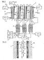
- la figure 3 montre comme la figure 1 un évaporateur-mélangeur conçu selon l'invention, comportant quatre étages montés en série,
- la figure 4 montre le diagramme de températures lorsqu'on traverse le dispositif de la figure 3,
- la figure 5 montre le schéma d'une installation utilisant un dispositif évaporateur à trois étages associé à des échangeurs-récupérateurs de chaleur,
- - la figure 6 montre à plus grande échelle un détail de construction utilisant une paroi perméable à la vapeur entre la surface d'évaporation et la surface de condensation d'un évaporateur-mélangeur,
- - la figure 7 montre en coupe verticale une installation comprenant un évaporateur-mélangeur à trois étages en série associé à des échangeurs-récupérateurs de chaleur et constituant une construction de forme cylindrique circulaire,
- -la figure 8 montre en coupe schématique l'utilisation de plusieurs évaporateurs-mélangeurs montés en série pour engendrer, à partir d'une source de chaleur à bas niveau, de la chaleur à niveau plus élevé et simultanément du froid,
- FIG. 1 shows in schematic vertical section the constitution of a single-stage evaporator-mixer used in the context of the invention,
- - the. Figure 2 shows the temperature diagram. when crossing the evaporator-mixer of Figure 1 ' ,
- FIG. 3 shows, like FIG. 1, an evaporator-mixer designed according to the invention, comprising four stages connected in series,
- FIG. 4 shows the temperature diagram when passing through the device of FIG. 3,
- FIG. 5 shows the diagram of an installation using a three-stage evaporator device associated with heat exchanger-recuperators,
- FIG. 6 shows on a larger scale a construction detail using a vapor permeable wall between the evaporation surface and the condensation surface of an evaporator-mixer,
- FIG. 7 shows in vertical section an installation comprising an evaporator-mixer with three stages in series associated with heat exchangers-recoverers and constituting a construction of circular cylindrical shape,
- FIG. 8 shows in schematic section the use of several evaporator-mixers mounted in series to generate, from a low level heat source, heat at a higher level and simultaneously cold,
On se reportera tout d'abord à la figure 1, qui illustre un dispositif formant évaporateur-mélangeur utilisé dans le cadre de l'invention repéré dans son ensemble EM, permettant de transférer une quantité de chaleur Q empruntée à une source thermique de bas niveau dite "source froide" vers une deuxième source à température plus élevée dite "source chaude". En d'autres termes, le dispositif évaporateur-mélangeur permet de transférer une quantité de chaleur Q disponible à une température déterminée, par exemple 25°C apportée sur une face d'une première plaque 1 du dispositif et de la libérer après traversée du dispositif sur une face d'une deuxième plaque 2 à une température plus élevée, par exemple 45°C.We will first refer to Figure 1, which illustrates a device forming an evaporator-melan geur used within the framework of the invention identified as a whole EM, making it possible to transfer a quantity of heat Q borrowed from a low level thermal source called "cold source" to a second source at higher temperature called "hot source". In other words, the evaporator-mixer device makes it possible to transfer a quantity of heat Q available at a determined temperature, for example 25 ° C. brought to one face of a
Dans l'exemple de réalisation illustré schématiquement, la source de chaleur disponible à bas niveau est constituée par un courant de fluide, par exemple une eau résiduaire sensiblement à la température de la "source froide", amenée par un conduit 3 en échange de chaleur avec une face extérieure 1A de la plaque 1 du dispositif.In the embodiment illustrated schematically, the heat source available at low level consists of a stream of fluid, for example waste water substantially at the temperature of the "cold source", brought by a
La chaleur est prélevée au dispositif à la température de la "source chaude" par un fluide caloporteur, tel par exemple que de l'èau amenée par une conduit 4 en échange de chaleur avec la face extérieure 2A de la plaque 2 du dispositif.The heat is taken from the device at the temperature of the "hot source" by a heat transfer fluid, such as, for example, water supplied by a
Le transfert de chaleur de la plaque 1 à la plaque 2 et l'élévation du niveau thermique de la chaleur transférée se fait grâce à l'évaporation d'un film d'un fluide (solvant), tel par exemple que de l'eau douce 5 qui ruisselle en descendant le long de la face intérieure 1B de la plaque 1 réchauffée par le fluide 3 constituant la source de chaleur à bas niveau disponible, et par la condensation de la vapeur produite dont le transfert est schématisé par les flèches 6, sur la face intérieure 2B de la plaque 2 en mélange avec un second fluide ou une solution saturée d'un soluté (saumure) s'écoulant en un film mouillant la face 2B de la plaque 2.The transfer of heat from
Ce transfert de chaleur et le relèvement du niveau de la chaleur transportée sont rendus possibles par l'application des lois de la thermodynamique dès lors que le "solvant" constituant le film 5 et la "solution" constituant le film 7 sont en équilibre de tension de vapeur à des températures différentes.This heat transfer and the raising of the level of the transported heat are made possible by the application of the laws of thermodynamics as soon as the "solvent" constituting the film 5 and the "solution" constituting the film 7 are in voltage equilibrium. of steam at different temperatures.
L'exemple thermique représenté correspond à l'utilisation pour le film 5 d'un film d'eau douce et pour le film 7 d'une solution sensiblement saturée de chlorure de calcium dans l'eau.The thermal example shown corresponds to the use for film 5 of a fresh water film and for film 7 of a substantially saturated solution of calcium chloride in water.
La figure 2 donne exemplairement le diagramme des températures permettant d'obtenir, en tenant compte des chutes thermiques à travers les plaques minces d'échange 1 et 2, une température du fluide de sortie de 45°C avec une température de fluide d'entrée à 25°C.FIG. 2 gives an exemplary diagram of the temperatures making it possible to obtain, taking into account the thermal drops through the
Pour que le dispositif puisse fonctionner, il suffit d'alimenter le plaque 1 en fluide thermique à bas niveau 3, d'alimenter le film d'eau douce 5, d'alimenter le film de saumure 7 et de récupérer la chaleur à plus haut niveau par le fluide d'échange caloporteur 4.For the device to function, it suffices to supply the
Lors de ce transfert de chaleur, de l'eau douce s'évapore, qu'il faut régénérer ou rajouter en complément, et la saumure se dilue, et il faut soit apporter du sel frais, soit régénérer le sel à partir de la saumure. Bien évidemment, l'énergie "noble" qui permet de relever la température de la chaleur empruntée à la source froide est apportée par la chaleur de dissolution du sel dans l'eau.During this heat transfer, fresh water evaporates, which must be regenerated or added as a complement, and the brine dilutes, and either fresh salt must be added or the salt must be regenerated from the brine . Obviously, the "noble" energy which makes it possible to raise the temperature of the heat borrowed from the cold source is provided by the heat of dissolution of the salt in the water.
Dans la suite de la description, et par manière de simplification, on parlera essentiellement d'eau et de saumure, ou éventuellement de "solvant", "soluté" et de "solution"; il faut bien comprendre que l'invention peut fonctionner avec diverses sortes de solvants et de solutés, pourvu qu'il existe une chaleur de dissolution relativement importante du soluté dans le solvant, plus forte étant la chaleur de dissolution, plus grande étant la possibilité de relever en un seul étage d'évaporation-mélange le niveau thermique de la source froide. Parmi de tels couples de "solvant" et de "soluté", on peut citer notamment les couples suivants:
- -eau/chlorure de lithium,
- -eau/bromure de lithium,
- -eau/chlorure de calcium,
- - eau/soude caustique,
- - eau/chlorure de zinc,
- - eau/acide sulfurique.
- -water / lithium chloride,
- -water / lithium bromide,
- -water / calcium chloride,
- - water / caustic soda,
- - water / zinc chloride,
- - water / sulfuric acid.
L'utilisation de l'eau comme solvant est avantageuse en ce que l'eau est d'une part un solvant économique, et d'autre part présente une chaleur importante de vaporisation.The use of water as a solvent is advantageous in that the water is on the one hand an economical solvent, and on the other hand has a high heat of vaporization.
D'autre part, le choix du couple solvant-solution pourra être déterminé par des conditions d'utilisation locales et des critères de résistance des matériaux et de corrosion. Des additifs pourront éventuellement être ajoutée à la solution pour limiter les phénomènes de corrosion.On the other hand, the choice of the solvent-solution couple can be determined by local conditions of use and criteria of resistance of materials and corrosion. Additives may possibly be added to the solution to limit corrosion phenomena.
Si l'on veut obtenir un relèvement de température important de la source froide à la source chaude, sans faire appel à des couples solvant- soluté très corrosifs tels que eau-acide sulfurique, on monte, comme illustré aux figures 3 et 4, en série plusieurs évaporateurs-mélangeurs conformément à l'invention.If we want to obtain a significant temperature rise from the cold source to the hot source, without using very corrosive solvent-solute couples such as water-sulfuric acid, we mount, as illustrated in Figures 3 and 4, several evaporator-mixers in accordance with the invention.
Ainsi, comme illustré à la figure 3, quatre évaporateurs-mélangeurs sont montés en série les une derrière les autres.Thus, as illustrated in FIG. 3, four evaporator-mixers are mounted in series one behind the other.
Sur la face extérieure 1A de la plaque 11 du premier étage d'évaporateur-mélangeur EM1 est apportée la chaleur à bas niveau de la source froide dont le courant 3 apporte sa chaleur à la plaque 11, Le film d'eau 51 qui ruisselle le long de la plaque 11 s'évapore dans le volume laissé libre entre la plaque 11 et la plaque en regard 8 sur laquelle ruisselle le film de saumure 71 qui assure la dissolution et condensation de la vapeur 6 assurant simultanément le transfert de la chaleur Q et le relèvement de la température comme illustré par le diagramme de température de la figure 4. La plaque 8, par sa face en regard avec la plaque 11, forme surface de condensation de la vapeur, et par son autre face, forme face d'évaporation du film d'eau 52 du deuxième étage d'évaporateur-mélangeur EM2.On the
Tout se passe dans le deuxième étage EM2 comme dans le premier étage, à ceci près que le film d'eau 52 est évaporé dans le second évaporateur-mélangeur EM2 à une température plus élevée que celle à laquelle le film d'eau 51 est évaporé dans le premier étage EM,. Dans l'exemple illustré, on a supposé un relèvement très modeste de 25°C initial à 45°C au niveau du film 52,Everything takes place in the second stage EM 2 as in the first stage, except that the film of water 5 2 is evaporated in the second evaporator-mixer EM 2 at a higher temperature than that at which the film of water 5 1 is evaporated in the first stage EM ,. In the example illustrated, we assumed a very modest rise from initial 25 ° C to 45 ° C at the level of the film 5 2 ,
La vapeur du film 52 produite est dissoute et condensée à température plus élevée, soit dans l'exemple illustré 75°C, dans le film de saumure 72 qui ruisselle le long de la face en regard de la plaque suivante 9 formant plaque de condensation du second étage EM2 par une de ses faces et plaque d'évaporation du troisième étage EM3 par son autre face.The vapor of the film 5 2 produced is dissolved and condensed at a higher temperature, that is to say in the example illustrated at 75 ° C., in the brine film 7 2 which flows along the face opposite the next plate 9 forming a plate of condensation of the second stage EM 2 by one of its faces and evaporation plate of the third stage EM 3 by its other face.
De proche en proche, en quatre étages, on peut très facilement, avec un couple eau/solution de chlorure de calcium obtenir un relèvement de température de la chaleur Q empruntée à la source froide 3 de 25°C à 120°C, récupérée par le fluide caloporteur 4 qui recueille la chaleur sur la face extérieure de la dernière plaque 24 de l'évaporateur-mélangeur EM4.Gradually, in four stages, it is very easy, with a couple of water / calcium chloride solution, to raise the temperature of the heat Q borrowed from
Bien entendu, les pressions dans chaque étage EM1 seront ajustées à la valeur correspondant sensiblement à l'équilibre des pressions de vapeur du couple eau/solution saline aux températures envisagées de chaque étage.Of course, the pressures in each stage EM 1 will be adjusted to the value corresponding substantially to the equilibrium of the vapor pressures of the water / saline solution couple at the temperatures envisaged for each stage.
Les différences de pression entre les faces extérieures 11 et 24 du système pourront être facilement encaissées en prévoyant (non représentées) quelques entretoises entre les plaques successives 11, 8, 9, 10, 124.The pressure differences between the
On notera enfin que les évaporateurs-mélangeurs seront d'autant plus efficaces et d'autant moins encombrants que l'intervalle entre les plaques en regard d'évaporation et de condensation sera réduit, de telle sorte que le transfert de la vapeur, illustré par les flèches 6, pourra être très efficace. Avec un tel dispositif, on peut escompter raisonnablement obtenir des densités de flux de transfert de chaleur de l'ordre de 20 à 30 kw/m2 et davantage.Finally, it will be noted that the evaporator-mixers will be all the more efficient and all the less bulky as the interval between the plates facing evaporation and condensation will be reduced, so that the transfer of the vapor, illustrated by arrows 6 can be very effective. With such a device, one can reasonably expect to obtain heat transfer flux densities of the order of 20 to 30 kw / m 2 and more.
Dans certains cas, notamment dans le cas d'évaporateurs-mélangeurs travaillant à température relativement élevée, on pourra prévoir, comme illustré à la figure 6, interposées entre les plaques 1, 2 on regard de l'évaporateur-mélangeur EM des chicanes 11, 12 par exemple en métal poli réfléchissant, perforées d'un grand nombre de trous, n'offrant pratiquement pas de résistance au passage de la vapeur selon les flèches 6 mais s'opposant efficacement au rayonnement thermique de la plaque chaude 2 vers la plaque froide 1 et également au "primage", c'est-à-dire au transfert du film 5 vers le film 7 de gouttelettes du solvant liquide allant se dissoudre dans la solution 7 sans évaporation, ce qui diminuerait considérablement le transfert de chaleur dans un tel évaporateur-mélangeur. On se reportera maintenant à la figure 5 dans laquelle on a décrit une installation utilisant des évaporateurs-mélangeurs montés en série associés à des échangeurs-récupérateurs de chaleur, et ce pour l'alimentation en chaleur d'une "source chaude" à partir d'une source de chaleur résiduaire constituant "source froide". Dans l'exemple illustré, on a supposé un dispositif comportant trois évaporateurs-mélangeurs montés en série EM,, EM2, EMs permettant le transfert d'une quantité de chaleur Q fournie par exemple à la température de 25°C et sa récupération à la température supérieure de 80°C.In certain cases, in particular in the case of evaporator-mixers working at a relatively high temperature, provision may be made, as illustrated in FIG. 6, interposed between the
Dans l'exemple illustré, la chaleur à bas niveau est apportée par le fluide caloporteur 3 à la plaque d'entrée 1 du premier évaporateur-mélangeur EM,. Le fluide caloporteur de la source de chaleur résiduaire pénètre en 13 par exemple à la température de 25°C et ressort en 14 à la température de 20°C. Cet abaissement de température de la "source froide" est mis à profit pour évaporer le film d'eau 51 dans le premier étage d'évaporateur-mélangeur EM,.In the example illustrated, the low level heat is supplied by the
Le fonctionnement des trois échangeurs-mélangeurs en série est identique à celui des autres échangeurs de la figure 3 et ne sera pas décrit à nouveau.The operation of the three exchanger-mixers in series is identical to that of the other exchangers in FIG. 3 and will not be described again.
Par contre, on met à profit la chaleur sensible des diluats (solutions diluées) 7,, 72, 73 quittant les échangeurs-mélangeurs EM,, EM2, EM3 à des températures par exemple respectivement de 45°C, 65°C et 85°C pour réchauffer dans des échangeurs de chaleur de tout type approprié 15, 16, 17 les alimentations de saumure fraîche 18 (amenées par exemple à 20°C) nécessaires au fonctionnement des trois étages, et de même les alimentations d'eau fraîche amenée en 19 (par exemple à 20°C) aux étages 2 et 3 d'évaporateur-mélangeur.On the other hand, use is made of the sensible heat of the diluates (diluted solutions) 7 ,, 7 2 , 7 3 leaving the exchanger-mixers EM ,, EM 2 , EM 3 at temperatures for example of 45 ° C, 65 ° C and 85 ° C for heating in heat exchangers of any
Les solutions diluées sont recueillies en 20, par exemple vers 25°C et seront soit régénérées, soit stockées, soit encore éventuellement rejetées selon les conditions d'implantation de l'installation (notamment si l'on est près de la mer ou de grande fleuves acceptant les rejets de solutions salines diluées).The diluted solutions are collected in 20, for example around 25 ° C and will either be regenerated, or stored, or even possibly rejected according to the conditions of installation of the installation (especially if one is near the sea or large rivers accepting the discharge of dilute saline solutions).
En 21, on a illustré l'entrée du fluide caloporteur que l'on pourra faire traverser l'échangeur 17 afin de le réchauffer avant de venir, au contact de la plaque 2 de condensation du dernier étage d'évàporateur-mélangeur EM3 pour fournir en 22 le fluide caloporteur chaud sortant par exemple à la température de 80°C.At 21, there is illustrated the entry of the heat transfer fluid which can be passed through the
Sur la figure 5, on a admis que l'eau douce amenée en tête de chaque film en évaporation est entièrement évaporée au cours de son ruissellement sur la paroi. Bien entendu, s'il n'en est pas ainsi et qu'un résidu d'eau pure parvient en pied de paroi, il suffit de munir le dispositif d'un système de gouttières pour collecter cette eau et la ré-injecter en tête de paroi (ce système n'est pas représenté ici).In FIG. 5, it has been admitted that the fresh water brought to the head of each evaporating film is entirely evaporated during its runoff on the wall. Of course, if this is not so and a residue of pure water reaches the bottom of the wall, it suffices to provide the device with a system of gutters to collect this water and re-inject it at the head. wall (this system is not shown here).
Les échangeurs à plaques planes du type décrit aux figures précédentes présentent l'avantage d'une simplicité de fabrication et conviennent très bien pour des usages à relativement basse température et faible pression. Par contre, si les températures et donc les pressions augmentent, ces échangeurs, qui comportent de nombreux joints, risquent d'être mal adaptés.The exchangers with flat plates of the type described in the preceding figures have the advantage of simplicity of manufacture and are very suitable for uses at relatively low temperature and low pressure. On the other hand, if the temperatures and therefore the pressures increase, these exchangers, which have many seals, risk being ill-suited.
A la figure 7, on a décrit schématiquement un échangeur évaporateur-mélangeur à trois étages en série de type cylindrique permettant le fonctionnement de l'installation sous des pressions et températures élevées.In FIG. 7, a schematic description of a three-stage evaporator-mixer exchanger in series of cylindrical type allowing the operation of the installation under high pressures and temperatures.
Selon l'exemple illustré, le dispositif comprend trois échangeurs-mélangeurs disposés concentriquement EM,, EMz, EM3 fonctionnant en série selon le même principe que décrit aux figures précédentes et notamment à la figure 5.According to the example illustrated, the device comprises three exchanger-mixers arranged concentrically EM ,, EM z , EM 3 operating in series according to the same principle as described in the preceding figures and in particular in FIG. 5.
Ces trois échangeurs-mélangeurs sont montés à l'intérieur d'une cuve cylindrique verticale 24. En dessous des évaporateurs-mélangeurs EMy, EM2, EM3 sont montés, par exemple logés également dans la cuve 24, des échangeurs de chaleur 25 pouvant fonctionner comme les échangeurs 15, 16, 17 de la figure 5.These three exchanger-mixers are mounted inside a vertical
Le dispositif est essentiellement adapté à la revalorisation des condensats de vapeurs basse pression, sous forme d'eau liquide pouvant être introduite dans l'installation comme illustré en 26 vers 70-100°C par exemple. Une partie de cette eau traverse selon la flèche 27 le centre de l'échangeur et s'échauffe au contact de la dernière paroi de condensation 23 de l'échangeur EM3 jusqu'à la température maximale fonction de l'installation pouvant atteindre par exemple 150 à 200°C. On récupère ainsi en 28 de la vapeur moyenne pression par exemple à 15 bars et 200°C adaptée à tout usage industriel.The device is essentially suitable for the revalorization of low pressure vapor condensates, in the form of liquid water which can be introduced into the installation as illustrated in 26 around 70-100 ° C. for example. Part of this water passes along arrow 27 in the center of the exchanger and heats up in contact with the
Une autre partie de l'eau provenant de l'alimentation à 70-100°C circule selon les flèches 29 à l'intérieur de l'enceinte 24 et sert à réchauffer les premiers étages des échangeurs 25 et le premier étage de l'évaporateur-mélangeur EM1 par sa face extérieure 11 qui baigne à l'intérieur de l'enveloppe 24 dans ce courant d'eau ascendant. Le surplus, s'il y en a, de l'eau ainsi fournie dans l'appareil peut être extrait comme indiqué en 30 par exemple à une température comprise entre 65 et 95°C.Another part of the water coming from the supply at 70-100 ° C. circulates according to the
L'eau douce qui ruisselle sur la plaque extérieure 11 de l'échangeur-mélangeur de premier étage est amenée comme indiqué en 31 à la température où elle est disponible de 70 à 100°C, cette eau étant avantageusement constituée par une petite quantité dérivée de la source 26. La saumure est amenée comme indiqué par les flèches 32 sur la face de la plaque 33 communiquant avec l'espace intérieur de l'échangeur EM1 à partir d'une source de stockage 34 par exemple à 20°C et après échauffement à travers les échangeurs 25.The fresh water flowing on the
Les échangeurs 25 sont quant à eux réchauffés par les solutions diluées de saumure s'échappant des trois étages des évaporateurs-mélangeurs EM,, EM2, EM3 comme indiqué par les flèches 34, 35,36 et ce, à des températures allant en croissant jusqu'à la température de la plaque la plus chaude 23 du dernier étage d'échangeur-mélangeur EM3. Les solutions diluées s'échappent des échangeurs 25 comme indiqué en 37 par exemple vers 105°C: Elles sont avantageusement traitées à cette température par évaporation-séparation pour reconstituer la saumure. Ce traitement d'évaporation-séparation pourra se faire dans des appareils qui seront décrits ci-après.The
Evidemment, les évaporateurs-mélangeurs EM2 et EM3 fonctionnent de façon semblable à l'échangeur-mélangeur EM1 mais à des températures supérieures. En 38, 39, on a repéré respectivement les alimentations des films d'eau du deuxième et troisième étages (à des températures allant en croissant) et en 40, 41 les alimentations en saumure des deuxième et troisième étages (à des températures allant en croissant).Obviously, the EM 2 and EM 3 evaporator-mixers operate similarly to the EM 1 exchanger-mixer but at higher temperatures. In 38, 39, the second and third stage water film supplies were identified respectively (at increasing temperatures) and in 40, 41 the second and third stage brine supplies (at increasing temperatures) ).
Pour reconstituer les solutions concentrées (saumures) à partir des solutions diluées (diluats), on pourra utiliser tout dispositif distillateur ou évaporateur-séparateur connu et utilisé industriellement par exemple pour le dessalement de l'eau de mar. Ces évaporateurs-séparateurs pourront du reste avoir une structure semblable ou identique à celle des évaporateurs-mélangeurs EM ci-dessus décrits, mais fonctionnant en quelque sorte en sens inverse.To reconstitute the concentrated solutions (brines) from the dilute solutions (diluates), it is possible to use any known distiller or evaporator-separator device used industrially for example for the desalination of seawater. These evaporator-separators can moreover have a structure similar or identical to that of the EM evaporator-mixers described above, but operating in some way in the opposite direction.
On se reportera maintenant à la figure 8 qui décrit un système particulièrement bien adapté à l'utilisation de bâtiments industriels ou d'habitation.We will now refer to FIG. 8 which describes a system particularly well suited to the use of industrial or residential buildings.
Dans les habitations, et dans certaines industries, on a besoin à la fois de chaleur, notamment pour le chauffage des bâtiments, et à la fois de froid, notamment. pour la conservation de denrées alimentaires et autres.In homes, and in some industries, we need both heat, especially for heating buildings, and both cold, in particular. for the preservation of foodstuffs and others.
Conformément à l'invention, il est possible, à partir d'une installation unique de produire à la fois le froid et à la fois le chaud, en associant de façon judicieuse des évaporateurs-mélangeurs à une source de chaleur résiduaire à bas niveau.According to the invention, it is possible, from a single installation, to produce both cold and both hot, by judiciously combining evaporator-mixers with a low level waste heat source.
Ainsi, comme illustré à la figure 8, si l'on dispose d'une source de chaleur Q1 à 25°C, on alimentera comme illustré en 68 le volume 69 d'échange fermé d'un côté par la plaque 70 de vaporisation du premier étage EM1 d'un évaporateur-mélangeur, et de l'autre côté par le plaque 71 de condensation d'un évaporateur-mélangeur EMo. Dans l'exemple illustré, l'évaporateur-mélangeur EM1 est suivi d'un deuxième étage d'évaporateur-mélangeur, ces deux évaporateurs-malangeurs fonctionnant en série et formant pompe à chaleur comme il a été décrit précédemment notamment en relation avec les figures 1 et 3. Dans l'exemple illustré, on suppose que la paroi 72 extérieure de l'échangeur-mélangeur EM2 est portée par exemple vers 65°C, permettant de chauffer vers 60°C le fluide caloporteur 73 assurant le chauffage de l'installation.Thus, as illustrated in FIG. 8, if there is a heat source Q 1 at 25 ° C, the exchange volume 69 closed on one side by the
En ce qui concerne l'échangeur-mélangeur EMo, celui-ci fonctionne en réfrigérateur, la surface 71a a de la plaque 71 servant de surface de condensation sur laquelle ruisselle la saumure, ce qui permet par évaporation du film 75 d'eau sur la plaque 76 extérieure de l'échangeur-mélangeur EMo d'obtenir la réfrigération, par exemple de 5°C à 0°C d'un fluide frigoporteur en contact avec la face extérieure de la plaque 76.As regards the exchanger-mixer EM o , it operates in a refrigerator, the surface 71a has plate 71 serving as a condensing surface on which the brine flows, which makes it possible by evaporation of the
On notera que dans une telle installation, et contrairement aux techniques classiques, il n'est pas plus cher ni plus difficile de produire du froid que du chaud, et l'installation totale n'est pas notablement compliquée.It will be noted that in such an installation, and contrary to conventional techniques, it is neither more expensive nor more difficult to produce cold than hot, and the total installation is not notably complicated.
Une situation particulièrement intéressante sera celle où le flux de chaleur Q3 fourni à la partie du bâtiment à chauffer sera égal, en valeur absolue, au flux de chaleur Q4 prélevé à la partie du bâtiment à refroidir. Dans ces conditions, il n'y aura même plus besoin de faire appel à un flux de chaleur ambiante, car on aura:
- Q2-Ql =0.
- Q2-Ql = 0.
D'autre part, de nombreux autres fluides que l'eau ou même des mélanges de fluides pourront être utilisés comme "solvants". Dans le cas d'utilisations à basses températures (0°C et en dessous), on prendra un fluide plus volatif que l'eau, par exemple l'amoniac, un alcool, etc... Dans le cas d'utilisations à hautes températures (200°C et au dessus), on utilisera un fluide moins volatil que l'eau, par exemple un métal volatil tel que mercure, cadmium, sodium...On the other hand, many other fluids than water or even mixtures of fluids can be used as "solvents". In the case of uses at low temperatures (0 ° C and below), we will take a more volatile fluid than water, for example ammonia, an alcohol, etc ... In the case of uses at high temperatures (200 ° C and above), use a fluid that is less volatile than water, for example a volatile metal such as mercury, cadmium, sodium ...
Claims (5)
Priority Applications (1)
| Application Number | Priority Date | Filing Date | Title |
|---|---|---|---|
| DE8585101378T DE3176997D1 (en) | 1980-08-11 | 1981-08-05 | System for the revaluation of low-level thermal energy using phenomena of evaporation, and solution of two fluids being in equilibrium of vapour pressure at different temperatures |
Applications Claiming Priority (4)
| Application Number | Priority Date | Filing Date | Title |
|---|---|---|---|
| FR8017676 | 1980-08-11 | ||
| FR8017676A FR2488379B1 (en) | 1980-08-11 | 1980-08-11 | METHOD AND DEVICES FOR RECOVERY OF LOW LEVEL THERMAL ENERGY USING EVAPORATION AND MIXTURE PHENOMENA OF TWO VAPOR PRESSURE BALANCED FLUIDS |
| FR8113846 | 1981-07-16 | ||
| FR8113846A FR2509845B2 (en) | 1981-07-16 | 1981-07-16 | METHOD AND DEVICES FOR RECOVERY OF LOW LEVEL THERMAL ENERGY USING EVAPORATION AND MIXTURE PHENOMENA OF TWO VAPOR PRESSURE BALANCED FLUIDS UNDER DIFFERENT TEMPERATURES, AND APPLICATION TO THE RECOVERY OF THERMAL ENERGY |
Related Child Applications (1)
| Application Number | Title | Priority Date | Filing Date |
|---|---|---|---|
| EP85101378.9 Division-Into | 1981-08-05 |
Publications (3)
| Publication Number | Publication Date |
|---|---|
| EP0046112A2 EP0046112A2 (en) | 1982-02-17 |
| EP0046112A3 EP0046112A3 (en) | 1982-09-01 |
| EP0046112B1 true EP0046112B1 (en) | 1986-02-26 |
Family
ID=26221945
Family Applications (2)
| Application Number | Title | Priority Date | Filing Date |
|---|---|---|---|
| EP85101378A Expired EP0148756B1 (en) | 1980-08-11 | 1981-08-05 | System for the revaluation of low-level thermal energy using phenomena of evaporation, and solution of two fluids being in equilibrium of vapour pressure at different temperatures |
| EP81401260A Expired EP0046112B1 (en) | 1980-08-11 | 1981-08-05 | Device and systems for the revaluation of low-level thermal energy using phenomena of evaporation, and solution of two fluids being in equilibrium of vapour pressure at different temperatures |
Family Applications Before (1)
| Application Number | Title | Priority Date | Filing Date |
|---|---|---|---|
| EP85101378A Expired EP0148756B1 (en) | 1980-08-11 | 1981-08-05 | System for the revaluation of low-level thermal energy using phenomena of evaporation, and solution of two fluids being in equilibrium of vapour pressure at different temperatures |
Country Status (3)
| Country | Link |
|---|---|
| US (2) | US4527621A (en) |
| EP (2) | EP0148756B1 (en) |
| DE (1) | DE3173876D1 (en) |
Families Citing this family (16)
| Publication number | Priority date | Publication date | Assignee | Title |
|---|---|---|---|---|
| GB8308137D0 (en) * | 1983-03-24 | 1983-05-05 | Ici Plc | Compression-type heat pumps |
| GB8308135D0 (en) * | 1983-03-24 | 1983-05-05 | Ici Plc | Centrifugal heat pump |
| FR2557277B1 (en) * | 1983-12-22 | 1986-04-11 | Alsthom Atlantique | THERMAL INDUCTION MACHINE |
| GB8400324D0 (en) * | 1984-01-06 | 1984-02-08 | Ici Plc | Heat pumps |
| US4553409A (en) * | 1984-07-12 | 1985-11-19 | Hitachi Zosen Corporation | Multiple regeneration multiple absorption type heat pump |
| FR2591504B1 (en) * | 1985-12-13 | 1990-04-20 | Centre Nat Rech Scient | PROCESS OF EVAPORATION-CONDENSATION OF RUNOFF FILMS, ELEMENTS FOR ITS IMPLEMENTATION AND ITS APPLICATIONS. |
| DE3833666C2 (en) * | 1988-10-04 | 1994-02-17 | Gerd Dr Ing Wilhelm | Compound systems from normal and inverse rectification |
| AU647102B2 (en) * | 1990-02-27 | 1994-03-17 | Chen-Yen Cheng | Absorption vapor pressure enhancement process and its applications in high level refrigeration and separation processes |
| US5291942A (en) * | 1993-05-24 | 1994-03-08 | Gas Research Institute | Multiple stage sorption and desorption process and apparatus |
| FR2754594B1 (en) * | 1996-10-10 | 1998-12-31 | Gaz De France | FRIGOPOMPE |
| FR2756621B1 (en) * | 1996-11-29 | 1999-02-19 | Gaz De France | THERMO-FRIGOPOMPE |
| FR2757255B1 (en) * | 1996-12-13 | 1999-03-05 | Gaz De France | MULTI-STAGE HEAT AND / OR COLD ABSORPTION DEVICE |
| WO1998058217A1 (en) * | 1997-06-18 | 1998-12-23 | Gas Research Institute | Flat-plate absorbers and evaporators for absorption coolers |
| HU0100463D0 (en) * | 2001-01-29 | 2001-03-28 | Szopko Mihaly | Method and device for absorption heat pumping |
| CA2778101A1 (en) * | 2012-05-24 | 2013-11-24 | Jean Pierre Hofman | Power generation by pressure differential |
| CN109681944A (en) * | 2019-02-13 | 2019-04-26 | 上海虹铂环保科技有限公司 | It is a kind of to be combined the unit using electric air source water heater group depth recovered flue gas latentization waste heat |
Citations (1)
| Publication number | Priority date | Publication date | Assignee | Title |
|---|---|---|---|---|
| US2182453A (en) * | 1936-01-18 | 1939-12-05 | William H Sellew | Heat transfer process and apparatus |
Family Cites Families (22)
| Publication number | Priority date | Publication date | Assignee | Title |
|---|---|---|---|---|
| DE278076C (en) * | 1911-08-11 | |||
| US1683434A (en) * | 1924-01-09 | 1928-09-04 | Siemens Schuckertwerke Gmbh | Method of heating buildings |
| FR675258A (en) * | 1928-05-18 | 1930-02-07 | Industrikemiska Ab | Evaporation method and device |
| GB372339A (en) * | 1930-01-09 | 1932-05-02 | Siemens Ag | Utilizing absorption refrigerating machines for heat insulating purposes |
| US1913468A (en) * | 1930-01-09 | 1933-06-13 | Hoover Co | Arrangement for reducing the transmission of heat |
| GB422150A (en) * | 1932-12-21 | 1935-01-07 | Siemens Ag | Improvements relating to heat converters comprising absorption apparatus |
| US2162607A (en) * | 1935-11-20 | 1939-06-13 | American Mach & Foundry | Supply of material in wrapping machines |
| FR840283A (en) * | 1937-07-06 | 1939-04-21 | Improvements to refrigeration machines operating by the affinity of a fluid, such as water vapor, for other substances | |
| FR1056314A (en) * | 1952-02-15 | 1954-02-25 | Methods and devices relating to absorption refrigeration machines | |
| US3306346A (en) * | 1962-12-03 | 1967-02-28 | Donald F Othmer | Method for cooling volatile liquids |
| DE1444337A1 (en) * | 1963-11-13 | 1968-11-28 | Forsch Ges Verfahrenstechnik E | Evaporator |
| US3483710A (en) * | 1968-06-13 | 1969-12-16 | Crane Co | Cascade absorption refrigeration system |
| US3822192A (en) * | 1971-12-08 | 1974-07-02 | Aluminum Co Of America | Evaporative method |
| FR2180526B1 (en) * | 1972-04-19 | 1977-01-14 | Do Vnipiche | |
| FR2274564A1 (en) * | 1974-06-17 | 1976-01-09 | Rigollot Georges | Multiple effect evapn plant for commercial desalination - used modular evapn. stages assembled in prefabricated chamber |
| US4009575A (en) * | 1975-05-12 | 1977-03-01 | said Thomas L. Hartman, Jr. | Multi-use absorption/regeneration power cycle |
| DE2552538A1 (en) * | 1975-11-22 | 1977-05-26 | Hans Dipl Ing Dr Herrmann | Flame-proofing agent for polymers esp. polyacrylonitrile and polyester - has distillatory placed in boiler combustion chamber and evaporated refrigerant is passed to condenser |
| DE2648855A1 (en) * | 1976-10-25 | 1978-04-27 | Herbst Donald | Heat loss reduction unit for oil-fired boilers - uses absorption refrigerator with condenser and generator in flue gas flow |
| DE2743488A1 (en) * | 1977-09-28 | 1979-03-29 | Karl Friedrich Prof Dr Knoche | METHOD AND DEVICE FOR USE OF SOLAR ENERGY FOR SPACE HEATING |
| US4223535A (en) * | 1978-12-22 | 1980-09-23 | Kumm Emerson L | Absorption solar powered air conditioning system with storage capacity |
| DE2939423A1 (en) * | 1979-09-28 | 1981-04-16 | Alefeld, Georg, Prof.Dr., 8000 München | METHOD FOR OPERATING A HEATING SYSTEM CONTAINING AN ABSORBER HEAT PUMP AND HEATING SYSTEM FOR CARRYING OUT THIS METHOD |
| DE3169318D1 (en) * | 1980-03-17 | 1985-04-25 | Hitachi Ltd | System for heat energy conversion |
-
1981
- 1981-08-05 EP EP85101378A patent/EP0148756B1/en not_active Expired
- 1981-08-05 DE DE8181401260T patent/DE3173876D1/en not_active Expired
- 1981-08-05 EP EP81401260A patent/EP0046112B1/en not_active Expired
- 1981-08-07 US US06/291,145 patent/US4527621A/en not_active Expired - Fee Related
-
1984
- 1984-11-29 US US06/658,843 patent/US4606404A/en not_active Expired - Fee Related
Patent Citations (1)
| Publication number | Priority date | Publication date | Assignee | Title |
|---|---|---|---|---|
| US2182453A (en) * | 1936-01-18 | 1939-12-05 | William H Sellew | Heat transfer process and apparatus |
Also Published As
| Publication number | Publication date |
|---|---|
| US4527621A (en) | 1985-07-09 |
| EP0148756A3 (en) | 1986-04-23 |
| EP0148756B1 (en) | 1989-03-08 |
| EP0046112A3 (en) | 1982-09-01 |
| DE3173876D1 (en) | 1986-04-03 |
| US4606404A (en) | 1986-08-19 |
| EP0148756A2 (en) | 1985-07-17 |
| EP0046112A2 (en) | 1982-02-17 |
Similar Documents
| Publication | Publication Date | Title |
|---|---|---|
| EP0046112B1 (en) | Device and systems for the revaluation of low-level thermal energy using phenomena of evaporation, and solution of two fluids being in equilibrium of vapour pressure at different temperatures | |
| Rahimi-Ahar et al. | Solar assisted modified variable pressure humidification-dehumidification desalination system | |
| US8202402B2 (en) | System and method of passive liquid purification | |
| EP1636138A2 (en) | Distillation methods and devices, in particular for producing potable water | |
| FR2471562A1 (en) | MODULAR DEVICE FOR PERFORMING HEATING OR COOLING FROM SOLAR ENERGY BY AN INTERMITTENT CYLINDER OF ADSORPTION HEAT PUMP, AND APPARATUS COMPRISING SUCH DEVICES | |
| WO2001096244A1 (en) | Distillation method and appliances for fresh water production | |
| EP3096851A1 (en) | Facility and method for treating water pumped in a natural environment by evaporation/condensation | |
| EP0072305B1 (en) | Method of storing mechanical or thermal energy in the form of chemical energy and of at least partially regaining the stored energy, and device for carrying out this method | |
| BE1024466B1 (en) | Mechanical water vapor desalination unit | |
| EP2354710B1 (en) | Device and method for recovering heat from the fumes of a thermal power station | |
| FR2531418A1 (en) | Desalination plant | |
| US20200324248A1 (en) | Apparatus for solar-assisted water distillation using waste heat of air conditioners | |
| EP0007835A1 (en) | Method for separating a gas and a condensable vapour and its applications | |
| FR2488379A1 (en) | Heat generating system combined with heat pump - uses heat transferred by vapours at equilibrium pressure between two heat exchanger trickle plates | |
| FR2591504A1 (en) | Process for evaporation-condensation of trickling films, components for its implementation and its applications | |
| US20120267231A1 (en) | System and method of passive liquid purification | |
| WO2007144024A1 (en) | Thermal exchange device | |
| FR2922001A1 (en) | Heating installation for producing e.g. domestic hot water, in building, has heat pump collecting heat from fluid in exchanger and transferring heat to fluid in another exchanger, and third exchanger transferring heat to domestic hot water | |
| FR2468085A1 (en) | SORPTION REFRIGERATING APPARATUS, METHOD FOR OPERATING THIS APPLIANCE AND USE THEREOF | |
| Stefano et al. | Setting up of a cost-effective continuous desalination plant based on coupling solar and geothermal energy | |
| FR2890650A1 (en) | Desalinization of seawater by vacuum vaporization, comprises obtaining vaporization of water by a thermodynamic unit with a frigorific group or a heat pump | |
| EP0836059A1 (en) | Cold pump | |
| FR3075934A1 (en) | AIR PROCESSING CENTER COMPRISING AN ABSORPTION DEVICE AND ASSOCIATED METHOD | |
| FR2586091A1 (en) | HEAT EXCHANGE DEVICE PERFORMED BY TWO FLUIDS WITH INDEPENDENT CIRCUITS | |
| BE888555A (en) | DISTILLATION APPARATUS, |
Legal Events
| Date | Code | Title | Description |
|---|---|---|---|
| PUAI | Public reference made under article 153(3) epc to a published international application that has entered the european phase |
Free format text: ORIGINAL CODE: 0009012 |
|
| AK | Designated contracting states |
Designated state(s): BE DE GB LU NL SE |
|
| PUAL | Search report despatched |
Free format text: ORIGINAL CODE: 0009013 |
|
| AK | Designated contracting states |
Designated state(s): BE DE GB LU NL SE |
|
| 17P | Request for examination filed |
Effective date: 19820630 |
|
| GRAA | (expected) grant |
Free format text: ORIGINAL CODE: 0009210 |
|
| AK | Designated contracting states |
Designated state(s): BE DE GB LU NL SE |
|
| REF | Corresponds to: |
Ref document number: 3173876 Country of ref document: DE Date of ref document: 19860403 |
|
| BECN | Be: change of holder's name |
Effective date: 19860226 |
|
| PLBE | No opposition filed within time limit |
Free format text: ORIGINAL CODE: 0009261 |
|
| STAA | Information on the status of an ep patent application or granted ep patent |
Free format text: STATUS: NO OPPOSITION FILED WITHIN TIME LIMIT |
|
| 26N | No opposition filed | ||
| RAP2 | Party data changed (patent owner data changed or rights of a patent transferred) |
Owner name: ETABLISSEMENT PUBLIC DIT: CENTRE NATIONAL DE LA R |
|
| PGFP | Annual fee paid to national office [announced via postgrant information from national office to epo] |
Ref country code: SE Payment date: 19910717 Year of fee payment: 11 Ref country code: LU Payment date: 19910717 Year of fee payment: 11 |
|
| PGFP | Annual fee paid to national office [announced via postgrant information from national office to epo] |
Ref country code: GB Payment date: 19910730 Year of fee payment: 11 |
|
| PGFP | Annual fee paid to national office [announced via postgrant information from national office to epo] |
Ref country code: BE Payment date: 19910801 Year of fee payment: 11 |
|
| PGFP | Annual fee paid to national office [announced via postgrant information from national office to epo] |
Ref country code: NL Payment date: 19910831 Year of fee payment: 11 |
|
| PGFP | Annual fee paid to national office [announced via postgrant information from national office to epo] |
Ref country code: DE Payment date: 19910925 Year of fee payment: 11 |
|
| EPTA | Lu: last paid annual fee | ||
| PG25 | Lapsed in a contracting state [announced via postgrant information from national office to epo] |
Ref country code: LU Free format text: LAPSE BECAUSE OF NON-PAYMENT OF DUE FEES Effective date: 19920805 Ref country code: GB Effective date: 19920805 |
|
| PG25 | Lapsed in a contracting state [announced via postgrant information from national office to epo] |
Ref country code: SE Effective date: 19920806 |
|
| PG25 | Lapsed in a contracting state [announced via postgrant information from national office to epo] |
Ref country code: BE Effective date: 19920831 |
|
| BERE | Be: lapsed |
Owner name: CENTRE NATIONAL DE LA RECHERCHE SCIENTIFIQUE CNRS Effective date: 19920831 |
|
| PG25 | Lapsed in a contracting state [announced via postgrant information from national office to epo] |
Ref country code: NL Effective date: 19930301 |
|
| GBPC | Gb: european patent ceased through non-payment of renewal fee |
Effective date: 19920805 |
|
| PG25 | Lapsed in a contracting state [announced via postgrant information from national office to epo] |
Ref country code: DE Effective date: 19930501 |
|
| EUG | Se: european patent has lapsed |
Ref document number: 81401260.5 Effective date: 19930307 |