EP0045939B1 - Vorrichtung zur Belüftung des häuslichen und/oder industriellen Abwassers - Google Patents
Vorrichtung zur Belüftung des häuslichen und/oder industriellen Abwassers Download PDFInfo
- Publication number
- EP0045939B1 EP0045939B1 EP19810106113 EP81106113A EP0045939B1 EP 0045939 B1 EP0045939 B1 EP 0045939B1 EP 19810106113 EP19810106113 EP 19810106113 EP 81106113 A EP81106113 A EP 81106113A EP 0045939 B1 EP0045939 B1 EP 0045939B1
- Authority
- EP
- European Patent Office
- Prior art keywords
- section
- suction pipe
- arrangement according
- sewage
- suction
- Prior art date
- Legal status (The legal status is an assumption and is not a legal conclusion. Google has not performed a legal analysis and makes no representation as to the accuracy of the status listed.)
- Expired
Links
- 239000010865 sewage Substances 0.000 title claims description 29
- 238000005273 aeration Methods 0.000 title description 4
- 238000011144 upstream manufacturing Methods 0.000 claims description 13
- 230000000630 rising effect Effects 0.000 claims description 4
- 230000001154 acute effect Effects 0.000 claims description 3
- 230000003247 decreasing effect Effects 0.000 claims 1
- 239000002351 wastewater Substances 0.000 description 57
- 239000007788 liquid Substances 0.000 description 9
- 239000001301 oxygen Substances 0.000 description 9
- 229910052760 oxygen Inorganic materials 0.000 description 9
- QVGXLLKOCUKJST-UHFFFAOYSA-N atomic oxygen Chemical compound [O] QVGXLLKOCUKJST-UHFFFAOYSA-N 0.000 description 8
- 239000000203 mixture Substances 0.000 description 7
- XLYOFNOQVPJJNP-UHFFFAOYSA-N water Substances O XLYOFNOQVPJJNP-UHFFFAOYSA-N 0.000 description 5
- 238000010276 construction Methods 0.000 description 4
- 238000012423 maintenance Methods 0.000 description 4
- 238000009423 ventilation Methods 0.000 description 4
- 239000011324 bead Substances 0.000 description 3
- 230000015556 catabolic process Effects 0.000 description 3
- 238000006243 chemical reaction Methods 0.000 description 3
- 238000006731 degradation reaction Methods 0.000 description 3
- 239000010840 domestic wastewater Substances 0.000 description 3
- 239000007789 gas Substances 0.000 description 3
- 239000010842 industrial wastewater Substances 0.000 description 3
- 239000000126 substance Substances 0.000 description 3
- 238000004065 wastewater treatment Methods 0.000 description 3
- 230000035943 smell Effects 0.000 description 2
- 238000005276 aerator Methods 0.000 description 1
- 238000006065 biodegradation reaction Methods 0.000 description 1
- 230000031018 biological processes and functions Effects 0.000 description 1
- 238000001311 chemical methods and process Methods 0.000 description 1
- 238000004140 cleaning Methods 0.000 description 1
- 230000008878 coupling Effects 0.000 description 1
- 238000010168 coupling process Methods 0.000 description 1
- 238000005859 coupling reaction Methods 0.000 description 1
- 230000006378 damage Effects 0.000 description 1
- 238000009826 distribution Methods 0.000 description 1
- 238000005265 energy consumption Methods 0.000 description 1
- 230000007613 environmental effect Effects 0.000 description 1
- 238000004519 manufacturing process Methods 0.000 description 1
- 239000000463 material Substances 0.000 description 1
- 230000002093 peripheral effect Effects 0.000 description 1
- 238000005086 pumping Methods 0.000 description 1
- 150000003568 thioethers Chemical class 0.000 description 1
- 231100000331 toxic Toxicity 0.000 description 1
- 230000002588 toxic effect Effects 0.000 description 1
Images


Classifications
-
- C—CHEMISTRY; METALLURGY
- C02—TREATMENT OF WATER, WASTE WATER, SEWAGE, OR SLUDGE
- C02F—TREATMENT OF WATER, WASTE WATER, SEWAGE, OR SLUDGE
- C02F3/00—Biological treatment of water, waste water, or sewage
- C02F3/02—Aerobic processes
- C02F3/12—Activated sludge processes
- C02F3/1278—Provisions for mixing or aeration of the mixed liquor
- C02F3/1294—"Venturi" aeration means
-
- B—PERFORMING OPERATIONS; TRANSPORTING
- B01—PHYSICAL OR CHEMICAL PROCESSES OR APPARATUS IN GENERAL
- B01F—MIXING, e.g. DISSOLVING, EMULSIFYING OR DISPERSING
- B01F23/00—Mixing according to the phases to be mixed, e.g. dispersing or emulsifying
- B01F23/20—Mixing gases with liquids
- B01F23/23—Mixing gases with liquids by introducing gases into liquid media, e.g. for producing aerated liquids
- B01F23/234—Surface aerating
-
- B—PERFORMING OPERATIONS; TRANSPORTING
- B01—PHYSICAL OR CHEMICAL PROCESSES OR APPARATUS IN GENERAL
- B01F—MIXING, e.g. DISSOLVING, EMULSIFYING OR DISPERSING
- B01F25/00—Flow mixers; Mixers for falling materials, e.g. solid particles
- B01F25/30—Injector mixers
- B01F25/31—Injector mixers in conduits or tubes through which the main component flows
- B01F25/314—Injector mixers in conduits or tubes through which the main component flows wherein additional components are introduced at the circumference of the conduit
- B01F25/3142—Injector mixers in conduits or tubes through which the main component flows wherein additional components are introduced at the circumference of the conduit the conduit having a plurality of openings in the axial direction or in the circumferential direction
-
- B—PERFORMING OPERATIONS; TRANSPORTING
- B01—PHYSICAL OR CHEMICAL PROCESSES OR APPARATUS IN GENERAL
- B01F—MIXING, e.g. DISSOLVING, EMULSIFYING OR DISPERSING
- B01F25/00—Flow mixers; Mixers for falling materials, e.g. solid particles
- B01F25/30—Injector mixers
- B01F25/31—Injector mixers in conduits or tubes through which the main component flows
- B01F25/314—Injector mixers in conduits or tubes through which the main component flows wherein additional components are introduced at the circumference of the conduit
- B01F25/3142—Injector mixers in conduits or tubes through which the main component flows wherein additional components are introduced at the circumference of the conduit the conduit having a plurality of openings in the axial direction or in the circumferential direction
- B01F25/31425—Injector mixers in conduits or tubes through which the main component flows wherein additional components are introduced at the circumference of the conduit the conduit having a plurality of openings in the axial direction or in the circumferential direction with a plurality of perforations in the axial and circumferential direction covering the whole surface
-
- C—CHEMISTRY; METALLURGY
- C02—TREATMENT OF WATER, WASTE WATER, SEWAGE, OR SLUDGE
- C02F—TREATMENT OF WATER, WASTE WATER, SEWAGE, OR SLUDGE
- C02F3/00—Biological treatment of water, waste water, or sewage
- C02F3/02—Aerobic processes
- C02F3/12—Activated sludge processes
- C02F3/24—Activated sludge processes using free-fall aeration or spraying
-
- Y—GENERAL TAGGING OF NEW TECHNOLOGICAL DEVELOPMENTS; GENERAL TAGGING OF CROSS-SECTIONAL TECHNOLOGIES SPANNING OVER SEVERAL SECTIONS OF THE IPC; TECHNICAL SUBJECTS COVERED BY FORMER USPC CROSS-REFERENCE ART COLLECTIONS [XRACs] AND DIGESTS
- Y02—TECHNOLOGIES OR APPLICATIONS FOR MITIGATION OR ADAPTATION AGAINST CLIMATE CHANGE
- Y02W—CLIMATE CHANGE MITIGATION TECHNOLOGIES RELATED TO WASTEWATER TREATMENT OR WASTE MANAGEMENT
- Y02W10/00—Technologies for wastewater treatment
- Y02W10/10—Biological treatment of water, waste water, or sewage
Definitions
- the invention relates to an arrangement for ventilation of domestic and / or industrial wastewater in the Abwasserdruckleitun g of a sewage system or a sewage treatment plant with a constriction and a suction opening in the sewage pressure line, the suction opening consists of several suction openings distributed around the circumference of a suction pipe.
- a device for the treatment of liquids in which aerators in the form of suction pipes are installed in a waste water stream, which are provided with suction openings for air all around at their constriction.
- the liquids to be treated are guided in the form of a partial flow branched off from a main flow through a drop channel via a contact point with a treatment liquid or a treatment gas to initiate a chemical or biological process to a container, with the suction openings in the area of the narrowest cross section of the drop channel the moving liquid, the treatment liquid and / or the treatment gas is sucked in and distributed in the liquid in the form of bubbles.
- the known device has in the narrowest cross-section of the drop channel tubes with a narrow passage cross-section, which penetrate the wall of the drop channel and with their outlet end for the gas to be supplied and / or the liquid for introducing the biological or chemical process into a region of high liquid velocity within the Pass the drop channel into it.
- the reaction area with the liquid to be treated is not sufficient in every case, so that additional units, compressors or the like are also to be used here to intensify the reaction.
- the object of the present invention is. to create an arrangement for the ventilation of domestic and / or industrial wastewater in the wastewater pressure line of a wastewater system or a wastewater treatment plant, which allows a strong air or oxygen entry into the wastewater in a simple and reliable manner with little space and maintenance requirements without additional units
- suction opening is arranged downstream behind the constriction in the usable suction pipe forming the end of the sewage pressure line and downstream of the suction pipe there is a vortex section for distributing the sucked air to the sewage pressure line and an open drop section behind the vortex section connects.
- the solution according to the invention ensures in a simple and reliable manner, without additional units such as compressors or pumps, a strong introduction of air or oxygen into the waste water with little space and maintenance requirements.
- a suction pipe is provided that can be inserted into the sewer in a suitable manner and has a constriction, downstream of which one or more suction openings are provided in the pipe wall.
- the narrowing of the suction pipe serves to increase the flow velocity of the waste water in the area of the narrowing.
- the wastewater stream flowing past the suction openings at a higher speed then sucks in a particularly large amount of air.
- the amount of oxygen added to the wastewater in the air is about 2 to 2.2 mg / l and is thus about as large as in wastewater treatment in the aeration tank.
- the oxygen introduced in this way reacts with the substances contained in the wastewater and continues the aerobic degradation of the wastewater. This prevents the occurrence of sulfides in the water, which would lead to the destruction of the piping material in the medium term.
- the device according to the invention is for this purpose at a suitable point moves in a shaft at the end of a pressure line, inserted into the sewage pressure line, so that no additional construction work has to be carried out.
- the device according to the invention operates completely maintenance-free and without additional energy consumption.
- the vortex section located downstream of the suction pipe intimately connects the sucked-in air with the substances contained in the waste water. For this purpose, the water is swirled intensively and the absorbed air is finely distributed in the wastewater, so that intensive biodegradation is guaranteed.
- the vortex section immediately downstream of the intake manifold contains a bend which has a cross section which increases in the flow direction and which is followed by the open drop section.
- the elbow In the area of its convex curvature, the elbow has a bulge at which the air / wastewater mixture is first swirled. The wastewater is then fed from the outlet of the elbow either via an impeller or directly into a drop section which has opposite wall sections with deflection profiles. When passing through the drop section, the wastewater is guided back and forth between the deflection profiles of the wall sections in order to lengthen the reaction section and, due to the multiple impact, the air or oxygen, finely divided, strike the wastewater.
- the vortex section consists of an open guide cone flanged to the suction pipe and widening downstream, which contains axially inward guide plates that swirl the waste water / air mixture that hits at a relatively high speed and blow the air into the waste water in finely divided form.
- the baffles guide the wastewater / air mixture centrally onto a rotationally symmetrical impact body, along the surface of which the wastewater / air mixture flows down and is swirled again by baffle arrangements. The waste water / air mixture is then released from the impact body to the outgoing sewer in a free-falling manner.
- the suction openings of the suction pipe preferably run at an acute angle to the flow axis and have a circular cross section.
- suction nozzles are attached to the outside of the suction pipe, which extend the suction openings axially outwards.
- the suction pipe particularly preferably has the shape of a first cone section that tapers in the direction of flow up to the constriction and then a second cone section that widens in the direction of flow.
- the suction openings are preferably all arranged in the second cone section.
- the cross section of the suction pipe is preferably of the same size at the upstream and downstream ends.
- the suction pipe and the vortex section are installed in a manhole at the end of a pressure line in the sewage system.
- the suction pipe is aligned vertically and is connected on the upstream side with a connecting pipe outside the shaft to the sewer, which arrives approximately at the sewer base.
- the connecting pipe has a rising path in which the waste water is raised at least 1. m from the sewer connection and then discharged to the suction pipe.
- the wastewater passes through the suction pipe, sucks in as much air as possible and is then swirled in the swirl section in the shaft and guided openly from the swirl section - within the shaft - to the outgoing channel.
- the required raising of the water in the rising section is brought about by the pump at the upstream opening of the pressure line; a separate pump or compressor unit is not required for the device according to the invention.
- the suction pipe is preferably arranged in an air duct, the inlet opening of which is connected to the surface of the earth. This ensures that only outside air containing oxygen gets into the waste water through the suction openings. The low-oxygen air in the shaft does not get into the suction openings.
- Fig. 1 shows an embodiment of the suction pipe for the device.
- the inner wall 5 of the suction pipe 4 has a rotationally symmetrical shape with an upstream opening 12 and a downstream opening 14 perpendicular to the axis of symmetry 16.
- the suction pipe has a constriction 6 which arises at the interface of two truncated cones connected to one another.
- the upstream opening 12 forms the base of a first cone section 4a tapering in the flow direction, which is adjoined by a second cone section 4b widening in the flow direction, the base of which is the downstream opening 14.
- the wall of the second cone section 4b is penetrated by suction openings 8, which are arranged in a plurality of rings on the circumference of the suction pipe and run at an acute angle to the direction of flow.
- a suction nozzle 10 In front of each suction opening 8, a suction nozzle 10 is placed, which extends the suction opening 8 axially outwards, so that the air sucked in or Oxygen passes through a longer suction channel before entering the flow path. It is essential that the suction openings are flush with the inner wall of the suction pipe 4, so that no parts protruding into the flow path impair the flow of the waste water.
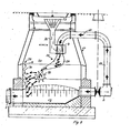
- Fig. 2 shows a shaft 17 which is embedded in the ground at the end of a waste water pressure line 2 and has a shaft bottom 18 with an inlet 19a at the end of the pressure line or the incoming waste water pressure line 2 and an outlet 19b on the outgoing waste water pressure line 3.
- An at least sectionally conical hood 19c is placed on the shaft bottom 18, which opens at its upper end into a cylinder section 19d, on which, with the street surface, a cover 19e is placed.
- the structure of the shaft is the same in the embodiments according to FIGS. 3 and 4.
- a suction pipe 4 with a vertically oriented axis is arranged in the conical section of the hood 19c of the shaft and is flanged upstream to a connecting pipe 60 which has a falling or rising section 62 at the upstream end and is flanged to the incoming sewage pressure line 2 with the upstream end.
- the height of rise from the axis of the sewage pressure line 2 to the highest point of the connecting pipe 60 is 1.2 m or more.
- the connecting tube 60 has the shape of an inverted U, of which one leg is formed by the riser section 62, and the other leg of which is cut off and replaced by the relatively short suction tube 4.
- the suction pipe 4 there is an air duct 70 which merges into a vertical section and then into a widening inlet opening 72 which sits at a predetermined distance under the cover 19e of the shaft 17.
- the air duct 70 feeds fresh air to the suction openings 8 of the suction tube 4, which fresh air flows into the air duct 70 from the outside through the cover 19e.
- the air duct 70 is held in the shaft by a holder 19f.
- a bend 22 is flanged to the downstream opening 14 of the intake manifold 4 and has an increasing cross section in the direction of flow and a bulge 24 in the region of its convexly curved wall.
- the cross section of the connecting pipe 60, the suction pipe 4 and the upstream opening of the elbow 22 is circular; however, the elbow 22 merges into a flat, rectangular cross section at its downstream end in the illustrated embodiment to generate a flat jet.
- the downstream end of the elbow 22 gives the waste water to an open drop section 40, which has mutually opposite deflection profiles 34, which are arranged on one side on an inner wall section 32 of the shaft 17.
- the deflection profiles 34 have obliquely downwardly inclined surfaces 36, from which the water jet is directed.
- the drop section is oriented essentially vertically and, at its lower end, discharges the waste water to outlet 19b of the outgoing waste water pressure line 3.
- Fig. Shows one of the Fig. Ent largely speaking embodiment of the arrangement in which the downstream end of the manifold 22 is shortened to install an impeller 28 between the manifold 22 and the drop section 30 in the waste water jet, which is moved by the waste water jet and the air entry and To further promote air distribution in wastewater.
- the impeller then releases the waste water to the drop section 30, which in FIG. 3 consists only of deflection profiles 34 placed on the inner wall of the shaft with deflecting surfaces 36 running obliquely downwards.
- the waste water falls down between the impeller and the drop section into the outlet 19b of the outgoing waste water pressure line 3.
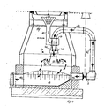
- FIGS. 3 and 3 show a third embodiment of the arrangement.
- the construction of the shaft and the connection of the suction pipe 4 via the connecting pipe 60 to the waste water pressure line 2 correspond to the construction of FIGS. 3 and 3.
- a downstream conical cone 40 is flanged instead of a bend, which is axially inward has directed baffles 42, on which the wastewater / air mixture strikes and thereby undergoes mixing for the first time.
- the wastewater / air mixture is also directed by the guide plates 42 onto the center of an impact body 50, which sits at a predetermined distance below the downstream end of the guide cone 40.
- the impact body 50 is a rotating body with a raised center, to which a circumferential groove is adjoined by a peripheral bead 54.
- the surface of the impact body 50 in particular the circumferential groove and the edge bead 54, represent a “baffle arrangement” 52 which is intended to move the waste water in a suitable manner and to distribute the air sucked into the suction pipe 4 in the waste water.
- the wastewater flowing over the bead 54 falls freely on the shaft bottom 18 and is then passed to the outlet 19b of the outgoing wastewater pressure line 3.
- the entire ventilation device can be coupled to the downstream or shaft-side flange of the connecting pipe 60 with a quick coupling and, like the intermediate plate forming the holder 19f, can be removed from the shaft with one hand. This does not hinder the maintenance and cleaning options for the subsequent downpipe.
- the arrangement is also suitable for use in wastewater treatment plants, in particular when transferring the wastewater from one basin to a subsequent basin and for aeration of return flows in sewage treatment plants.
Landscapes
- Chemical & Material Sciences (AREA)
- Life Sciences & Earth Sciences (AREA)
- Chemical Kinetics & Catalysis (AREA)
- Biodiversity & Conservation Biology (AREA)
- Microbiology (AREA)
- Hydrology & Water Resources (AREA)
- Engineering & Computer Science (AREA)
- Environmental & Geological Engineering (AREA)
- Water Supply & Treatment (AREA)
- Organic Chemistry (AREA)
- Sewage (AREA)
- Jet Pumps And Other Pumps (AREA)
Description
- Die Erfindung betrifft eine Anordnung zur Belüftung des häuslichen und/oder industriellen Abwassers in der Abwasserdruckleitung eines Abwassersystems oder einer Kläranlage mit einer eine Verengung und eine Ansaugöffnung in der Abwasserdruckleitung aufweisenden Vorrichtung, wobei die Ansaugöffnung aus mehreren am Umfang eines Saugrohres verteilten Saugöffnungen besteht.
- Bei den bekannten Abwassersystemen für häusliche und industrielle Abwässer münden die von den einzelnen Häusern herkommenden Anschlüsse in GefälIeIeitungen, welche das Abwasser bei nicht ausreichendem Freigefälle bis zur Kläranlage in eine Pumpstation leiten, wobei die Abwässer etwa 1 bis 2 Stunden unterwegs sind. Im Pumpraum verweilen die Abwässer etwa 10 bis 20 Minuten bis zum nächsten Pumpzyklus, mit dem die Pumpe die Abwässer in die anschließende Druckleitung gibt. Aufgrund der oftmals großen Längen verweilt das Abwasser in den Druckleitungen bis zu 4, ja sogar 6 Stunden. Der aerobe Abbau des Abwassers setzt schon in der Gefälleleitung ein und endet in der Regel wegen der relativ großen Verweildauer im Kanalsystem wegen Sauerstoffmangels in den Druckleitungen. Das Abwasser gelangt dann in Hauptsammelleitungen, es wird toxisch und kommt angefault an den Kläranlagen an. Neben der unerwünschten Belastung der Kläranlagen durch angefaultes Abwasser ist es insbesondere nachteilig, daß das Abwasser schon in den Druckleitung unangenehm riecht und diesen Geruch durch die Kanalschächte nach außen abgibt.
- Um diese Nachteile zu beseitigen, ist es bekannt, zwischen Druckleitungen und Hauptsammelleitung in bestimmten Fällen künstliche Belüftungsbecken anzubringen, in die mittels Kompressoren Luft eingeblasen wird. Dadurch wird zwar der aerobe Abbau des Abwassers fortgesetzt, und es kann unter Umständen ein Anfaulen des Wassers verhindert werden. Nachteilig dabei ist jedoch der sehr große Aufwand, der beim Bau und Betrieb eines derartigen Belüftungsbekkens anfällt. Aufgrund der Herstellungs- und Wartungskosten, sowie des Platzbedarfs und der damit verbundenen Umweltbelastung ist auch diese Lösung unbefriedigend.
- Aus der AT-B-336 517 ist eine Einrichtung zur Behandlung von Flüssigkeiten bekannt, bei der in einen Abwasserstrom Belüfter in Form von Saugrohren eingebaut sind, die an ihrer Verengung rundum mit Ansaugöffnungen für Luft versehen sind. Dabei werden die zu behandelnden Flüssigkeiten in Form eines von einem Hauptstrom abgezweigten Teilstromes durch einen Fallkanal über eine Kontaktstelle mit einer Behandlungsflüssigkeit oder einem Behandlungsgas zur Einleitung eines chemischen oder biologischen Prozesses zu einem Behälter geführt, wobei durch die Ansaugöffnungen im Bereich des engsten Querschnitts des Fallkanals durch die bewegte Flüssigkeit die Behandlungsflüssigkeit und/oder das Behandlungsgas angesaugt und in der Flüssigkeit bläschenförmig verteilt wird. Die bekannte Einrichtung weist im engsten Querschnitt des Fallkanals Röhrchen mit einem engen Durchtrittsquerschnitt auf, die die Wandung des Fallkanals durchdringen und die mit ihrem Auslaßende für das zuzuführende Gas und/oder die Flüssigkeit zur Einleitung des biologischen oder chemischen Prozesses in einen Bereich hoher Flüssigkeitsgeschwindigkeit innerhalb des Fallkanals hineinreichen. Trotz zahlreicher Ansaugöffnungen ist die Reaktionsfläche mit der zu behandelnden Flüssigkeit nicht in jedem Falle ausreichend, so daß auch hier zur Intensivierung der Reaktion zusätzliche Aggregate, Kompressoren o. dergl. einzusetzen sind.
- Aufgabe der vorliegenden Erfindung ist es. eine Anordnung zur Belüftung des häuslichen und/oder industriellen Abwassers in der Abwasserdruckleitung eines Abwassersystems oder einer Kläranlage zu schaffen, die in einfacher und zuverlässiger Weise ohne zusätzliche Aggregate einen starken Luft- oder Sauerstoffeintrag in das Abwasser bei geringem Raum- und Wartungsbedarf ermöglicht.
- Diese Aufgabe wird erfindungsgemäß dadurch gelöst, daß die Ansaugöffnung stromab wärts hinter der Verengung in dem das Ende der Abwasserdruckleitung bildenden, einsetzbaren Saugrohr angeordnet ist und sich stromabwärts hinter dem Saugrohr eine Wirbelstrecke zur Verteilung der angesaugten Luft an die Abwasserdruckleitung sowie hinter der Wirbelstrecke eine offene Fallstrecke anschließt.
- Die erfindungsgemäße Lösung stellt in einfacher und zuverlässiger Weise ohne zusätzliche Aggregate wie Kompressoren oder Pumpen einen starken Luft- oder Sauerstoffeintrag in das Abwasser bei geringem Raum- und Wartungsbedarf sicher. Als zentraler Bestandteil ist dabei ein Saugrohr vorgesehen, daß in den Abwasserkanal in geeigneter Weise eingefügt werden kann und eine Verengung besitzt, stromabwärts hinter der eine oder mehrere Ansaugöffnungen in der Rohrwand vorgesehen sind. Die Verengung des Saugrohres dient zur Erhöhung der Strömungsgeschwindigkeit des Abwassers im Bereich der Verengung. Der mit erhöhter Geschwindigkeit an den Saugöffnungen vorbeiströmende Abwasserstrom saugt dann eine besonders große Menge an Luft an. Die mit der Luft dem Abwasser zugesetzte Sauerstoffmenge beträgt bei optimaler Auslegung der Form und Anzahl an Saugöffnungen etwa 2 bis 2,2 mg/I und ist somit etwa so groß wie bei einer Abwasserbearbeitung im Belebungsbecken. Der auf diese Weise eingetragene Sauerstoff reagiert mit den im Abwasser enthaltenden Stoffen und setzt den aeroben Abbau des Abwassers fort. Dadurch wird das Auftreten von Sulfiden im Wasser verhindert, die mittelfristig zu einer Zerstörung des Rohrleitungsmaterials führen würden. Die erfindungsgemäße Vorrichtung wird dazu an geeigneter Stelle, bevorzugt in einem Schacht am Ende einer Druckleitung, in die Abwasserdruckleitung eingefügt, so daß keine zusätzlichen Bauarbeiten vorgenommen werden müssen. Da ferner keine zusätzlichen Kompressoren; Pumpen o. dgl. benötigt werden, arbeitet die erfindungsgemäße Vorrichtung vollkommen wartungsfrei und ohne zusätzlichen Energiebedarf. Die stromabwärts von dem Saugrohr angebrachte Wirbelstrecke bringt die angesaugte Luft innig mit den im Abwasser enthaltenen Stoffen in Verbindung. Zu diesem Zweck wird das Wasser intensiv verwirbelt und dabei die aufgenommene Luft fein im Abwasser verteilt, so daß ein intensiver biologischer Abbau gewährleistet ist.
- Gemäß einem bevorzugten Ausführungsbeispiel enthält die Wirbelstrecke unmittelbar stromabwärts hinter dem Saugrohr einen Krümmer, der einen in Stromrichtung zunehmenden Querschnitt aufweist, an welchen sich die offene Fallstrecke anschließt. Der Krümmer besitzt im Bereich seiner konvexen Krümmung eine Ausbuchtung, an der eine erste Verwirbelung des Luft/Abwassergemischs stattfindet. Anschließend wird das Abwasser vom Ausgang des Krümmers entweder über ein Flügelrad oder direkt in eine Fallstrecke gegeben, die einander gegenüberliegende Wandabschnitte mit Umlenkprofilen besitzt. Beim Durchlaufen der Fallstrecke wird das Abwasser zwischen den Umlenkprofilen der Wandabschnitte hin und her geführt, um die Reaktionsstrecke zu verlängern und durch den mehrfachen Aufprall die Luft bzw. den Sauerstoff fein zerteilt in das Abwasser einzuschlagen.
- Alternativ besteht die Wirbelstrecke aus einem am Saugrohr angeflanschten, sich stromabseitig weitenden, offenen Leitkegel, der axial einwärts gerichtete Leitbleche enthält, welche das mit relativ hoher Geschwindigkeit auftreffende Abwasser/Luftgemisch verwirbeln und die Luft fein zerteilt in das Abwasser schlagen. Die Leitbleche führen das Abwasser/Luftgemisch zentral auf einen rotationssymmetrischen Prallkörper, längs dessen Oberfläche das Abwasser/ Luftgemisch herabströmt und durch Leitblechanordnungen erneut verwirbelt wird. Anschließend wird das Abwasser/Luftgemisch vom Prallkörper freifallend an den abgehenden Kanal abgegeben.
- Bevorzugt verlaufen die Saugöffnungen des Saugrohrs unter einem spitzen Winkel zur Strömungsachse und weisen einen Kreisquerschnitt auf. Um eine möglichst gleichförmige Einströmung der angesaugten Luft zu gewährleisten, sind an der Außenseite des Saugrohrs Saugstutzen angebracht, welche die Saugöffnungen axial nach außen verlängern.
- Besonders bevorzugt weist das Saugrohr die Form eines sich in Strömungsrichtung bis zur Verengung hin verjüngenden ersten Kegelabschnitts und anschließend eines sich in Strömungsrichtung erweiternden zweiten Kegelabschnitts auf. Die Saugöffnungen sind bevorzugt alle im zweiten Kegelabschnitt angeordnet. Der Querschnitt des Saugrohrs ist bevorzugt am stromaufseitigen und am stromabseitigen Ende gleichgroß.
- Das Saugrohr und die Wirbelstrecke wird in einem Kanalschacht am Ende einer Druckleitung des Abwassersystems angebracht. Das Saugrohr wird vertikal ausgerichtet und ist Stromaufseitig mit einem Verbindungsrohr außerhalb des Schachts an den Kanal angeschlossen, der etwa in Höhe der Kanalsohle ankommt. Das Verbindungsrohr weist eine Steigstrecke auf, in der das Abwasser mindestens 1.m vom Kanalanschluß angehoben und dann an das Saugrohr abgegeben wird. Das Abwasser durchläuft das Saugrohr, saugt eine möglichst große Menge an Luft an und wird dann in der Wirbelstrecke im Schacht verwirbelt und von der Wirbelstrecke offen - innerhalb des Schachts - zu dem abgehenden Kanal geleitet. Die erforderliche Anhebung des Wassers in der Steigstrecke wird von der Pumpe an der stromaufseitigen Öffnung der Druckleitung bewirkt, ein separates Pump- oder Kompressoraggregat ist für die erfindungsgemäße Vorrichtung nicht erforderlich.
- Bevorzugt wird das Saugrohr in einem Luftkanai angeordnet, dessen Einlaßöffnung mit der Erdoberfläche in Verbindung steht. Dadurch ist sichergestellt, daß nur sauerstoffhaltige Außenluft durch die Saugöffnungen in das Abwasser gelangen. Die im Schacht befindliche, sauerstoffarme Luft gelangt nicht in die Saugöffnungen.
- Im folgenden werden Ausführungsbeispiele der Erfindung anhand der Zeichnung näher erläutert. Es zeigt
- Fig. 1 eine Ansicht des Saugrohrs teilweise im Schnitt,
- Fig. 2 eine erste Ausführungsform der Anordnung in einem Kanalschacht,
- Fig. 3 eine zweite Ausführungsform der Anordnung in einem Kanalschacht und
- Fig. 4 eine dritte Ausführungsform der Anordnung in einem Kanalschacht.
- Fig. 1 zeigt eine Ausführungsform des Saugrohrs für die Vorrichtung. Die Innenwand 5 des Saugrohrs 4 hat eine rotationssymmetrische Form mit einer stromaufseitigen Öffnung 12 und einer stromabseitigen Öffnung 14 senkrecht zur Symmetrieachse 16. Das Saugrohr weist eine Verengung 6 auf, die an der Nahtstelle zweier miteinander verbundener Kegelstümpfe entsteht. Die stromaufseitige Öffnung 12 bildet die Basis eines sich in Strömungsrichtung verjüngenden ersten Kegelabschnitts 4a, an den sich ein in Strömungsrichtung erweiternder zweiter Kegelabschnitt 4b anschließt, dessen Basis die stromabseitige Öffnung 14 ist. Die Wand des zweiten Kegelabschnitts 4b ist mit Saugöffnungen 8 durchsetzt, die in mehreren Kränzen am Umfang des Saugrohrs angeordnet sind und unter einem spitzen Winkel zur Strömungsrichtung verlaufen.
- Vor jede Saugöffnung 8 ist ein Saugstutzen 10 gesetzt, der die Saugöffnung 8 axial nach außen verlängert, so daß die angesaugte Luft oder der Sauerstoff vor dem Eintritt in den Strömungspfad einen längeren Saugkanal durchläuft. Wesentlich ist es dabei, daß die Saugöffnungen bündig mit der Innenwand des Saugrohrs 4 abschließen, daß also keine in den Strömungspfad hineinragenden Teile die Strömung des Abwassers beeinträchtigen.
- Fig. 2 zeigt einen Schacht 17, der am Ende einer Abwasserdruckleitung 2 in das Erdreich eingelassen ist und eine Schachtsohle 18 mit einem Einlaß 19a am Ende der Druckleitung oder der ankommenden Abwasserdruckleitung 2 und einen Auslaß 19b an der abgehenden Abwasserdruckleitung 3 aufweist. Auf die Schachtsohle 18 ist eine mindestens abschnittweise kegelförmige Haube 19c aufgesetzt, die an ihrem oberen Ende in einen Zylinderabschnitt 19d mündet, auf den, mit der Straßenfläche abschließend, ein Deckel 19e aufgesetzt ist. Der Aufbau des Schachts ist in den Ausführungsformen gemäß den Fig. 3 und 4 derselbe.
- Im kegelförmigen Abschnitt der Haube 19c des Schachts ist ein Saugrohr 4 mit vertikal ausgerichteter Achse angeordnet und stromaufseitig an ein Verbindungsrohr 60 angeflanscht, welches am stromaufseitigen Ende einen Fall- oder Steigabschnitt 62 besitzt und mit dem stromaufseitigen Ende an der ankommenden Abwasserdruckleitung 2 angeflanscht ist. Die Steighöhe von der Achse der Abwasserdruckleitung 2 bis zu dem höchsten Punkt des Verbindungsrohrs 60 beträgt 1,2 m oder mehr. Das Verbindungsrohr 60 hat die Form eines umgekehrten U, von dem ein Schenkel durch den Steigabschnitt 62 gebildet ist, und dessen anderer Schenkel abgeschnitten und durch das relativ kurze Saugrohr 4 ersetzt ist. Um die Verbindung vom Innenraum des Schachts 17 zu der außen etwa an der Schachtsohle 18 ankommenden Abwasserdruckleitung 2 herstellen zu können, muß die Haube 19c des Schachts durchbrochen werden.
- Um das Saugrohr4 ist ein Luftkanal 70 herumgelegt, der in einen vertikalen Abschnitt, und anschließend in eine sich weitende Einlaßöffnung 72 übergeht, die in vorgegebenem Abstand unter dem Deckel 19e des Schachts 17 sitzt. Der Luftkanal 70 führt den Saugöffnungen 8 des Saugrohrs 4 Frischluft zu, die durch den Deckel 19e von außen in den Luftkanal 70 einströmt. Der Luftkanal 70 wird im Schacht von einer Halterung 19f gehalten.
- An der stromabseitigen Öffnung 14 des Saugrohrs 4 ist ein Krümmer 22 angeflanscht, der in Strömungsrichtung einen zunehmenden Querschnitt und eine Ausbuchtung 24 im Bereich seiner konvex gekrümmten Wandung aufweist. Der Querschnitt des Verbindungsrohrs 60, des Saugrohrs 4 und der stromaufseitigen Öffnung des Krümmers 22 ist kreisförmig; der Krümmer 22 geht jedoch an seinem stromabseitigen Ende in der dargestellten Ausführungsform zur Erzeugung eines Flachstrahls in einen flachen, rechteckförmigen Querschnitt über.
- Das stromabseitige Ende des Krümmers 22 gibt das Abwasser auf eine offene Fallstrecke 40, die einander beabstandet gegenüberliegenden Umlenkprofile 34 aufweist, die auf der einen Seite an einem inneren Wandabschnitt 32 des Schachts 17 angeordnet sind. Die Umlenkprofile 34 haben schräg abwärts geneigte Umlenkflä chen 36, von denen der Wasserstrahl gelenkt wird. Die Fallstrecke ist im wesentlichen vertikal ausgerichtet und gibt an ihrem unteren Ende das Abwasser an den Ausl.aß 19b der abgehenden Abwasserdruckleitung 3 ab.
- Fig. zeigt eine der Fig. weitgehend ent sprechende Ausführungsform der Anordnung bei der das stromabseitige Ende des Krümmers 22 verkürzt ist, um zwischen Krümmer 22 und der Fallstrecke 30 in den Abwasserstrahl ein Flügelrad 28 einzubauen, welches vom Abwasserstrahl bewegt wird und den Lufteintrag und die Luftverteilung im Abwasser weiter fördern soll. Das Flügelrad gibt das Abwasser dann an die Fallstrecke 30 ab, die in Fig. 3 nur aus auf die Innen wand des Schachts aufgesetzten Umlenkprofilen 34 mit schräg abwärts laufenden Umlenkflächen 36 besteht. Das Abwässer fällt zwischen Flügelrad und Fallstrecke nach unten in den Auslaß 19b der abgehenden Abwasserdruckleitung 3.
- Fig.4 zeigt eine dritte Ausführungsform der Anordnung. Der Aufbau des Schachts sowie der Anschluß des Saugrohrs 4 über das Verbindungsrohr 60 an die Abwasserdruckleitung 2 entsprechen dem Aufbau der Fig. und 3. Am stromabseitigen Ende des Saugrohrs 4 ist anstelle eines Krümmers ein sich stromabwärts auf weitender offener Leitkegel 40 angeflanscht, der axial einwärts gerichtete Leitbleche 42 aufweist, auf die das Abwasser/Luftgemisch aufschlägt und dabei erstmalig eine Vermischung erfährt. Durch die Leitbleche 42 wird das Abwasser/ Luftgemisch ebenfalls auf das Zentrum eines Prallkörpers 50 gelenkt, der in vorgegebenem Abstand unter dem stromabseitigen Ende des Leitkegels 40 sitzt. Der Prallkörper 50 ist ein Rotationskörper mit einem erhabenen Zentrum, an das sich eine Umfangsnut ein anschließender Randwulst 54 anschließt. Die Oberfläche des Prallkörpers 50, insbesondere die Umfangsnut und der Randwulst 54 stellen eine »Leitblechanordnung« 52 dar, die das Abwasser geeignet bewegen und dabei die im Saugrohr 4 angesaugte Luft im Abwasser fein verteilen sollen. Das über den Randwulst 54 strömende Abwasser fällt frei auf die Schachtsohle 18 und wird dann an den Auslaß 19b der abgehenden Abwasser druckleitung 3 geleitet.
- Bei allen Ausführungsformen gemäß Fig. 2 bis 4 ist die gesamte Belüftungseinrichtung an dem stromabseitigen oder schachtseitigen Flansch des Verbindungsrohrs 60 mit einer Schnellkupplung ankoppelbar und kann ebenso wie auch das die Halterung 19f bildende Zwischenblech dadurch mit einem Handgriff aus dem Schacht entfernt werden. Dadurch werden die Wartungs-und Reinigungsmöglichkeiten für die anschließende Gefälleleitung nicht behindert.
- Neben dem Einsatz in Abwasserkanalsystemen eignet sich die Anordnung auch zur Verwendung in Abwasserkläranlagen, insbesondere bei der Übergabe des Abwassers von einem Becken in ein nachfolgendes Becken und zur Belüftung von Rückströmen in Kläranlagen.
Claims (16)
Applications Claiming Priority (2)
| Application Number | Priority Date | Filing Date | Title |
|---|---|---|---|
| DE3030416 | 1980-08-12 | ||
| DE3030416A DE3030416C2 (de) | 1980-08-12 | 1980-08-12 | Anordnung zur Belüftung des häuslichen und/oder industriellen Abwassers |
Publications (2)
| Publication Number | Publication Date |
|---|---|
| EP0045939A1 EP0045939A1 (de) | 1982-02-17 |
| EP0045939B1 true EP0045939B1 (de) | 1984-07-18 |
Family
ID=6109418
Family Applications (1)
| Application Number | Title | Priority Date | Filing Date |
|---|---|---|---|
| EP19810106113 Expired EP0045939B1 (de) | 1980-08-12 | 1981-08-05 | Vorrichtung zur Belüftung des häuslichen und/oder industriellen Abwassers |
Country Status (4)
| Country | Link |
|---|---|
| EP (1) | EP0045939B1 (de) |
| DE (1) | DE3030416C2 (de) |
| DK (1) | DK356981A (de) |
| ES (1) | ES504678A0 (de) |
Families Citing this family (5)
| Publication number | Priority date | Publication date | Assignee | Title |
|---|---|---|---|---|
| AT389298B (de) * | 1983-02-24 | 1989-11-10 | Waagner Biro Ag | Verfahren zur begasung einer fluessigkeit und einrichtung zur durchfuehrung des verfahrens |
| DE3630103A1 (de) * | 1986-09-04 | 1988-03-17 | Klein Schanzlin & Becker Ag | Vorrichtung zur belueftung einer abwasserdruckleitung |
| DE29613463U1 (de) * | 1996-07-24 | 1996-09-19 | Umweltgemeinschaft RundUm eV, 12681 Berlin | Vorrichtung zum Geruchsverschluß und zur Belüftung von Kanalschächten in Abwasseranlagen |
| FI131281B1 (fi) * | 2021-03-26 | 2025-01-27 | Teknologian Tutkimuskeskus Vtt Oy | Laitteisto ja menetelmä parantamaan kaasun liukenemista nesteeseen ja käyttö |
| CN117566903A (zh) * | 2024-01-03 | 2024-02-20 | 广东北控环保装备有限公司 | 一种基于好氧颗粒污泥的污水处理系统 |
Family Cites Families (7)
| Publication number | Priority date | Publication date | Assignee | Title |
|---|---|---|---|---|
| DE9149C (de) * | M. FRIEDRICH in Leipzig, Schulstrafse 9 | Selbstthätige Menge- und Klärvorrichtung für Desinfectionszwecke | ||
| DE1484829A1 (de) * | 1964-10-30 | 1969-05-29 | Jakob Eckert | Vorrichtung zur biologischen Klaerung von Abwaessern |
| DE1658148A1 (de) * | 1967-03-04 | 1970-09-03 | Zimmer Geb Goldenbaum Gertraud | Belueftungsverfahren und Vorrichtung dazu |
| AT288294B (de) * | 1968-11-20 | 1971-02-25 | Vogelbusch Gmbh | Vorrichtung zur Begasung von Flüssigkeiten |
| AT291134B (de) * | 1969-04-24 | 1971-07-12 | Vogelbusch Gmbh | Vorrichtung zum Begasen von Flüssigkeiten, insbesondere zum Belüften fließender Gewässer |
| AT336517B (de) * | 1975-07-07 | 1977-05-10 | Waagner Biro Ag | Verfahren und einrichtung zur behandlung von flussigkeiten, wie z.b. truben mit einem fluid |
| DE2832274C2 (de) * | 1978-07-22 | 1980-07-24 | Steag Ag, 4300 Essen | Belüftungsvonichtung für in Oberflächenwässer zurückzuleitende Abwässer, insbesondere für die Anreicherung von Gebrauchswässern mit Sauerstoff |
-
1980
- 1980-08-12 DE DE3030416A patent/DE3030416C2/de not_active Expired
-
1981
- 1981-08-05 EP EP19810106113 patent/EP0045939B1/de not_active Expired
- 1981-08-10 ES ES504678A patent/ES504678A0/es active Granted
- 1981-08-11 DK DK356981A patent/DK356981A/da not_active Application Discontinuation
Also Published As
| Publication number | Publication date |
|---|---|
| DE3030416A1 (de) | 1982-02-25 |
| DK356981A (da) | 1982-02-13 |
| DE3030416C2 (de) | 1983-06-30 |
| EP0045939A1 (de) | 1982-02-17 |
| ES8206717A1 (es) | 1982-08-16 |
| ES504678A0 (es) | 1982-08-16 |
Similar Documents
| Publication | Publication Date | Title |
|---|---|---|
| EP0174429B1 (de) | Vorrichtung zur Belüftung von Abwasser oder dgl. Medien in Belüftungsbecken | |
| DE2205612A1 (de) | Vorrichtung und Anlage zum Behandeln von Flüssigkeiten, insbesondere Trinkwasser oder Abwasser | |
| WO1990011811A1 (de) | Anordnung zum austreiben leichtflüchtiger verunreinigungen aus dem grundwasser | |
| EP0042620B1 (de) | Vorrichtung zum Aufbereiten von Gülle | |
| EP2578319B1 (de) | Brausekopf | |
| DE2434935A1 (de) | Verfahren und vorrichtung zum belueften einer fluessigkeit | |
| DE3030416C2 (de) | Anordnung zur Belüftung des häuslichen und/oder industriellen Abwassers | |
| DE2238869A1 (de) | Verfahren und anlage zur reinigung von abwasser | |
| DE4337091A1 (de) | Verfahren zum Betreiben eines Wasserbelüftungssystems sowie Vorrichtung, insbesondere zur Durchführung des Verfahrens | |
| AT522780B1 (de) | Vorrichtung zur reinigung von gas | |
| CH666627A5 (de) | Begasungsanlage sowie eine mit einer solchen versehene abwasserreinigungsanlage. | |
| DE1246603B (de) | Verfahren und Einrichtung zum Belueften von Abwasser in einem Belebungsbecken | |
| DE3101221A1 (de) | "einrichtung zur schaumflotation" | |
| DE8021540U1 (de) | Vorrichtung zur belueftung des haeuslichen und/oder industriellen abwassers | |
| CH668252A5 (en) | Biological sewage treatment - recycling sludge and sewage from settling basin by spraying it over surface of pre-settling basin | |
| DE1557181B2 (de) | Vorrichtung zum Eintragen von Gasen in Flüssigkeiten | |
| EP2065082A1 (de) | Luft-Reinigungsvorrichtung | |
| DE19933680C1 (de) | Vorrichtung zum Eintrag von Gas in flüssige Medien | |
| CH666020A5 (de) | Oberflaechenbelueftungskreisel sowie ein einen solchen enthaltendes abwasserbelueftungsbecken. | |
| EP0165228A2 (de) | Vorrichtung zum Belüften von strömenden Medien | |
| EP4487941A1 (de) | Vorrichtung zum eintragen eines gases in einem fluid und verwendung der vorrichtung | |
| DE4446888C2 (de) | Vorrichtung zur naßmechanischen Behandlung kontaminierter, körniger Materialien und deren Aufschlämmungen | |
| DE3200701A1 (de) | Verfahren und vorrichtung zum begasen und umwaelzen von fluessigkeiten | |
| DE3640964A1 (de) | Verfahren und vorrichtung zum einbringen von luft und/oder sauerstoff in belebungsbecken bei der abwasserreinigung und zur belueftung von seen, teichen und fluessen | |
| DE19506003A1 (de) | Einstrahldüse |
Legal Events
| Date | Code | Title | Description |
|---|---|---|---|
| PUAI | Public reference made under article 153(3) epc to a published international application that has entered the european phase |
Free format text: ORIGINAL CODE: 0009012 |
|
| AK | Designated contracting states |
Designated state(s): FR GB IT NL SE |
|
| 17P | Request for examination filed |
Effective date: 19820722 |
|
| GRAA | (expected) grant |
Free format text: ORIGINAL CODE: 0009210 |
|
| AK | Designated contracting states |
Designated state(s): FR GB IT NL SE |
|
| PG25 | Lapsed in a contracting state [announced via postgrant information from national office to epo] |
Ref country code: IT Free format text: LAPSE BECAUSE OF FAILURE TO SUBMIT A TRANSLATION OF THE DESCRIPTION OR TO PAY THE FEE WITHIN THE PRESCRIBED TIME-LIMIT;WARNING: LAPSES OF ITALIAN PATENTS WITH EFFECTIVE DATE BEFORE 2007 MAY HAVE OCCURRED AT ANY TIME BEFORE 2007. THE CORRECT EFFECTIVE DATE MAY BE DIFFERENT FROM THE ONE RECORDED. Effective date: 19840718 |
|
| ET | Fr: translation filed | ||
| PGFP | Annual fee paid to national office [announced via postgrant information from national office to epo] |
Ref country code: FR Payment date: 19840926 Year of fee payment: 4 |
|
| PGFP | Annual fee paid to national office [announced via postgrant information from national office to epo] |
Ref country code: SE Payment date: 19841231 Year of fee payment: 4 |
|
| PLBE | No opposition filed within time limit |
Free format text: ORIGINAL CODE: 0009261 |
|
| STAA | Information on the status of an ep patent application or granted ep patent |
Free format text: STATUS: NO OPPOSITION FILED WITHIN TIME LIMIT |
|
| 26N | No opposition filed | ||
| PGFP | Annual fee paid to national office [announced via postgrant information from national office to epo] |
Ref country code: NL Payment date: 19860831 Year of fee payment: 6 |
|
| PG25 | Lapsed in a contracting state [announced via postgrant information from national office to epo] |
Ref country code: SE Effective date: 19870806 |
|
| PG25 | Lapsed in a contracting state [announced via postgrant information from national office to epo] |
Ref country code: NL Effective date: 19880301 |
|
| NLV4 | Nl: lapsed or anulled due to non-payment of the annual fee | ||
| PG25 | Lapsed in a contracting state [announced via postgrant information from national office to epo] |
Ref country code: FR Free format text: LAPSE BECAUSE OF NON-PAYMENT OF DUE FEES Effective date: 19880429 |
|
| GBPC | Gb: european patent ceased through non-payment of renewal fee | ||
| REG | Reference to a national code |
Ref country code: FR Ref legal event code: ST |
|
| PG25 | Lapsed in a contracting state [announced via postgrant information from national office to epo] |
Ref country code: GB Free format text: LAPSE BECAUSE OF NON-PAYMENT OF DUE FEES Effective date: 19881118 |
|
| EUG | Se: european patent has lapsed |
Ref document number: 81106113.4 Effective date: 19880711 |