EP0045321A2 - Method and device for optical distance measurement - Google Patents
Method and device for optical distance measurement Download PDFInfo
- Publication number
- EP0045321A2 EP0045321A2 EP80104529A EP80104529A EP0045321A2 EP 0045321 A2 EP0045321 A2 EP 0045321A2 EP 80104529 A EP80104529 A EP 80104529A EP 80104529 A EP80104529 A EP 80104529A EP 0045321 A2 EP0045321 A2 EP 0045321A2
- Authority
- EP
- European Patent Office
- Prior art keywords
- beams
- diffraction
- grating
- plate
- measuring
- Prior art date
- Legal status (The legal status is an assumption and is not a legal conclusion. Google has not performed a legal analysis and makes no representation as to the accuracy of the status listed.)
- Granted
Links
- 238000005259 measurement Methods 0.000 title claims abstract description 41
- 230000003287 optical effect Effects 0.000 title claims abstract description 23
- 238000000034 method Methods 0.000 title claims description 41
- 239000013078 crystal Substances 0.000 claims abstract description 29
- 230000010363 phase shift Effects 0.000 claims abstract description 11
- 230000010287 polarization Effects 0.000 claims description 20
- 238000006073 displacement reaction Methods 0.000 abstract description 20
- 238000011156 evaluation Methods 0.000 abstract description 8
- 238000005286 illumination Methods 0.000 abstract description 5
- 238000004519 manufacturing process Methods 0.000 description 5
- 230000000737 periodic effect Effects 0.000 description 3
- 238000005215 recombination Methods 0.000 description 3
- 230000006798 recombination Effects 0.000 description 3
- 239000004065 semiconductor Substances 0.000 description 3
- 101100390736 Danio rerio fign gene Proteins 0.000 description 2
- 101100390738 Mus musculus Fign gene Proteins 0.000 description 2
- 230000000007 visual effect Effects 0.000 description 2
- 235000012431 wafers Nutrition 0.000 description 2
- 229910021532 Calcite Inorganic materials 0.000 description 1
- 229910000831 Steel Inorganic materials 0.000 description 1
- 238000010276 construction Methods 0.000 description 1
- 230000003111 delayed effect Effects 0.000 description 1
- 230000000694 effects Effects 0.000 description 1
- 238000004049 embossing Methods 0.000 description 1
- 238000005516 engineering process Methods 0.000 description 1
- 239000011521 glass Substances 0.000 description 1
- 238000003384 imaging method Methods 0.000 description 1
- 230000003993 interaction Effects 0.000 description 1
- 239000000463 material Substances 0.000 description 1
- 238000000691 measurement method Methods 0.000 description 1
- 230000028161 membrane depolarization Effects 0.000 description 1
- 238000007639 printing Methods 0.000 description 1
- 230000005855 radiation Effects 0.000 description 1
- 238000006748 scratching Methods 0.000 description 1
- 230000002393 scratching effect Effects 0.000 description 1
- 230000035945 sensitivity Effects 0.000 description 1
- 239000010959 steel Substances 0.000 description 1
Images


Classifications
-
- G—PHYSICS
- G03—PHOTOGRAPHY; CINEMATOGRAPHY; ANALOGOUS TECHNIQUES USING WAVES OTHER THAN OPTICAL WAVES; ELECTROGRAPHY; HOLOGRAPHY
- G03F—PHOTOMECHANICAL PRODUCTION OF TEXTURED OR PATTERNED SURFACES, e.g. FOR PRINTING, FOR PROCESSING OF SEMICONDUCTOR DEVICES; MATERIALS THEREFOR; ORIGINALS THEREFOR; APPARATUS SPECIALLY ADAPTED THEREFOR
- G03F9/00—Registration or positioning of originals, masks, frames, photographic sheets or textured or patterned surfaces, e.g. automatically
- G03F9/70—Registration or positioning of originals, masks, frames, photographic sheets or textured or patterned surfaces, e.g. automatically for microlithography
- G03F9/7065—Production of alignment light, e.g. light source, control of coherence, polarization, pulse length, wavelength
-
- G—PHYSICS
- G01—MEASURING; TESTING
- G01B—MEASURING LENGTH, THICKNESS OR SIMILAR LINEAR DIMENSIONS; MEASURING ANGLES; MEASURING AREAS; MEASURING IRREGULARITIES OF SURFACES OR CONTOURS
- G01B11/00—Measuring arrangements characterised by the use of optical techniques
-
- G—PHYSICS
- G01—MEASURING; TESTING
- G01B—MEASURING LENGTH, THICKNESS OR SIMILAR LINEAR DIMENSIONS; MEASURING ANGLES; MEASURING AREAS; MEASURING IRREGULARITIES OF SURFACES OR CONTOURS
- G01B11/00—Measuring arrangements characterised by the use of optical techniques
- G01B11/02—Measuring arrangements characterised by the use of optical techniques for measuring length, width or thickness
- G01B11/06—Measuring arrangements characterised by the use of optical techniques for measuring length, width or thickness for measuring thickness ; e.g. of sheet material
- G01B11/0608—Height gauges
-
- G—PHYSICS
- G01—MEASURING; TESTING
- G01D—MEASURING NOT SPECIALLY ADAPTED FOR A SPECIFIC VARIABLE; ARRANGEMENTS FOR MEASURING TWO OR MORE VARIABLES NOT COVERED IN A SINGLE OTHER SUBCLASS; TARIFF METERING APPARATUS; MEASURING OR TESTING NOT OTHERWISE PROVIDED FOR
- G01D5/00—Mechanical means for transferring the output of a sensing member; Means for converting the output of a sensing member to another variable where the form or nature of the sensing member does not constrain the means for converting; Transducers not specially adapted for a specific variable
- G01D5/26—Mechanical means for transferring the output of a sensing member; Means for converting the output of a sensing member to another variable where the form or nature of the sensing member does not constrain the means for converting; Transducers not specially adapted for a specific variable characterised by optical transfer means, i.e. using infrared, visible, or ultraviolet light
- G01D5/32—Mechanical means for transferring the output of a sensing member; Means for converting the output of a sensing member to another variable where the form or nature of the sensing member does not constrain the means for converting; Transducers not specially adapted for a specific variable characterised by optical transfer means, i.e. using infrared, visible, or ultraviolet light with attenuation or whole or partial obturation of beams of light
- G01D5/34—Mechanical means for transferring the output of a sensing member; Means for converting the output of a sensing member to another variable where the form or nature of the sensing member does not constrain the means for converting; Transducers not specially adapted for a specific variable characterised by optical transfer means, i.e. using infrared, visible, or ultraviolet light with attenuation or whole or partial obturation of beams of light the beams of light being detected by photocells
- G01D5/36—Forming the light into pulses
- G01D5/38—Forming the light into pulses by diffraction gratings
-
- G—PHYSICS
- G03—PHOTOGRAPHY; CINEMATOGRAPHY; ANALOGOUS TECHNIQUES USING WAVES OTHER THAN OPTICAL WAVES; ELECTROGRAPHY; HOLOGRAPHY
- G03F—PHOTOMECHANICAL PRODUCTION OF TEXTURED OR PATTERNED SURFACES, e.g. FOR PRINTING, FOR PROCESSING OF SEMICONDUCTOR DEVICES; MATERIALS THEREFOR; ORIGINALS THEREFOR; APPARATUS SPECIALLY ADAPTED THEREFOR
- G03F7/00—Photomechanical, e.g. photolithographic, production of textured or patterned surfaces, e.g. printing surfaces; Materials therefor, e.g. comprising photoresists; Apparatus specially adapted therefor
- G03F7/70—Microphotolithographic exposure; Apparatus therefor
- G03F7/70483—Information management; Active and passive control; Testing; Wafer monitoring, e.g. pattern monitoring
- G03F7/70605—Workpiece metrology
- G03F7/70616—Monitoring the printed patterns
- G03F7/70633—Overlay, i.e. relative alignment between patterns printed by separate exposures in different layers, or in the same layer in multiple exposures or stitching
-
- G—PHYSICS
- G03—PHOTOGRAPHY; CINEMATOGRAPHY; ANALOGOUS TECHNIQUES USING WAVES OTHER THAN OPTICAL WAVES; ELECTROGRAPHY; HOLOGRAPHY
- G03F—PHOTOMECHANICAL PRODUCTION OF TEXTURED OR PATTERNED SURFACES, e.g. FOR PRINTING, FOR PROCESSING OF SEMICONDUCTOR DEVICES; MATERIALS THEREFOR; ORIGINALS THEREFOR; APPARATUS SPECIALLY ADAPTED THEREFOR
- G03F9/00—Registration or positioning of originals, masks, frames, photographic sheets or textured or patterned surfaces, e.g. automatically
- G03F9/70—Registration or positioning of originals, masks, frames, photographic sheets or textured or patterned surfaces, e.g. automatically for microlithography
- G03F9/7049—Technique, e.g. interferometric
Definitions
- the invention relates to a method for optical distance measurement according to the preamble of the main claim and devices for performing the method.
- the measuring methods with visual observation that have been mainly used up to now can no longer be used in the submicron range, since they depend too much on the subjective assessment by the operator. This limitation also applies to the interferometric methods that work with visual observation.
- the measured variable is uses the light intensity, for example its sinusoidal variation in an interferometric measurement setup.
- the accuracy that can be achieved when evaluating this curve profile is limited by the strong dependence of the light intensity on many parameters of the measurement setup; in many cases, therefore, only a zero point determination can be carried out and the desired measured variable can only be determined with an accuracy which is in the order of magnitude of the light wavelength used.
- Such interferometric measuring systems are constructed, for example, in such a way that the length to be measured forms part of a Michelson interferometer construction.
- Further interferometric methods in which the phase change of light which has been diffracted on a moving or shifted optical grating is evaluated are described in the article "A New Interferometric Alignment Technique" by DC Flenders and HI Smith in Applied Physics Letters, volume 31, no 7 (October 1977), page 426 and in German Offenlegungsschrift 24 31 166. With these methods, the intensity of the interference phenomena is also evaluated, so that the accuracy restrictions mentioned above result.
- the present invention therefore has as its object to provide a method for optical distance measurement, the accuracy of which is fractions of a micrometer, which can be used for a large number of measurement tasks, can be carried out quickly and the results of which are largely independent of the operator;
- facilities for carrying out the method are to be specified which have a simple and stable structure and are adapted to various measuring tasks.
- the phase difference between two perpendicularly polarized partial bundles is measured, which is caused by the interaction of these partial bundles with lattice-shaped structures on the measurement object.
- these partial bundles are each provided with an optical grating; the partial beams that are diffracted and polarized perpendicular to one another from these gratings are optically combined into one beam and the phase difference is measured, from which the lateral displacement of the two objects results.
- the phase shift between different diffraction orders is measured, which occurs on a grating connected to the object during its displacement.
- a device which consists of a basic instrument with exchangeable measuring heads which are adapted to the respective measuring task.
- Various measuring heads with birefringent materials are specified for the optical probing of the measurement object and for the optical recombination of the partial beams.
- the signal is evaluated by electro-optical compensation of the phase difference in the reunited partial beams in the evaluation system, which is of the same design for all measuring heads.
- the high accuracy that can be achieved with this method is based on the generation of partial beams (diffraction orders) polarized perpendicular to one another, the phase difference of which can be measured with extraordinary accuracy by electro-optical compensation.
- the output signal of the electro-optical compensation device provides namely is an analog sawtooth signal that enables very good interpolation.
- the common signal evaluation for different measuring heads for probing the measuring object represents an extraordinarily diverse and easy-to-use measuring device.
- the achievable measuring accuracy is 0.02 pm or in the order of 1/1000 of the grating constant used; the measuring time is of the order of milliseconds and below.
- the optical structure of the measuring heads and the evaluation device is relatively simple; Resolution and focusing problems do not occur here.
- a light beam 4 z. B. a laser beam on an optically birefringent crystal 5, for. B. calcite, directed and split there into two partial rays, an ordinary (o) and an extraordinary (eo). Both partial beams leave the birefringent crystal 5 as parallel steel bundles 6, 7, the polarization direction of which is perpendicular to one another.
- the beams 6, 7 cover several grating periods, are diffracted at the two grids 2 and 3 and produce several diffraction beams of different orders;
- a first order of inflection is drawn in with reference numerals 8 and 9 (the diffraction angles shown are not to scale).
- the radiation beams 8, 9 diffracted at the gratings again enter the birefringent crystal 5; by the different refraction of ordinary and extraordinary Strähl, the two reflected bundles 8, 9 at Exit from the birefringent crystal 5 reunited and form a common exit bundle 10 with two perpendicularly polarized partial bundles.
- phase difference ⁇ M This phase difference can be measured very precisely by electro-optical compensation and thus represents a measure of the incorrect alignment of the two objects 1a, 1b. Details of this phase measurement are described with reference to FIG. 2.
- the measuring principle described above can also be used to check the exact reproducibility of the bearing of successive manufacturing steps, for example in the production of semiconductors with several mask exposure steps.
- a lattice structure 2 or 3 is applied to a single semiconductor wafer in each of the process steps to be examined and the relative position of these two grids compared with each other using the method described above.
- An offset of the grids can be caused by adjustment errors, imaging errors, temperature influences during manufacture, etc.
- FIG. 2 shows the schematic structure of a measuring device for carrying out the measuring method described with reference to FIG. 1; it consists of a special measuring head 20, in which the beam splitting takes place according to FIG. 1, and of lighting and evaluation devices.
- the illumination beam 4 is generated by a laser 21, which has a ⁇ / 2-.
- Plate 22 an electro-optical light modulator 23, a Soleil Babinet compensator 24 and an optical beam splitter 25 are connected downstream.
- the direction of polarization of the laser light is rotated with the 1/2 plate 22;
- the electro-optical light modulator 23 the incident light is split into two components polarized perpendicular to one another and a periodic phase shift between these two components is generated by applying a periodic electrical voltage.
- the phase difference between the two polarized sub-bundles can be set to a fixed initial value.
- the sub-beams leaving the modulator 23 are oriented such that their direction of polarization is parallel or perpendicular to the plane of incidence of the beam splitter.
- the X / 2 plate 22 is to be oriented accordingly at an angle of 45 ° to these two polarization directions.
- the laser beam 4 After entering the measuring head 20, the laser beam 4 is änein on the surface of the measurement object 1 (or the two objects 1a, 1b) bundled together.
- the focused light bundle passes through a birefringent plate 27, it splits into two mutually parallel light bundles 6, 7 according to FIG. 1, the mutual distance of which is determined by the crystal thickness.
- the details of the beam guidance according to FIG. 1 are not shown in FIG. 2.
- One bundle of light strikes one grid, the other bundle of light meets the other.
- the lens 5 is adjusted so that the focal point of the laser beams on the object covers approximately 10 grating periods. The light reflected and diffracted by the gratings is collimated after recombination by the crystal 27 in the lens 26.
- the +1 is preferably used for the phase measurement. or the -1.
- Diffraction order used.
- the desired diffraction order is masked out with a displaceable pinhole 28, which is attached in the beam path behind the partially transparent plate 25.
- the reflected exit bundle 10 passes behind the pinhole 28 through a polarizer 29 to a photodetector 30.
- the details of the electro-optical phase compensation in an arrangement according to FIG. 2 are described in the German patent application P 28 51 750.
- the measuring principle can be outlined as follows: in the electro-optical modulator, the linearly polarized light of the laser 21 is split into two perpendicularly polarized partial beams; depending on the value of the voltage applied to the modulator 23, a component is delayed with respect to the component polarized perpendicularly thereto.
- the two vertical sub-bundles enter the birefringent crystal 27 as ordinary or extraordinary rays and experience a different phase shift when reflected on lattice-like structures on the object 1.
- the two Partial beams polarized perpendicular to one another in the exit bundle 10 are thus composed, depending on the size of the relative phase shift, to form linear, elliptical or circularly polarized light, so that the analyzer 29 arranged in the cross position with respect to the linear polarization direction allows no, little or much light to reach the detector 30.
- the electro-optical light compensator 23 When a periodic voltage is applied to the electro-optical light compensator 23, the voltage or the phase difference that is required to compensate for the phase shift by reflection on mutually displaced grating structures can be determined.
- the zero crossing of the detector signal corresponds to this compensating phase shift.
- phase compensation can take place both on the lighting side and in the exit bundle.
- 2B shows an equivalent embodiment in which the electro-optical light modulator 23 and the North babinet compensator 24 are connected between the divider plate 25 and the analyzer 29.
- the laser beam 4 arrives directly from the laser 21 via beam splitter 25 into the measuring head 20.
- the same components have the same reference numerals.
- the output signal of the electro-optical compensation device according to FIGS. 2A, B is shown in FIG. 3.
- the interpolation between two intermediate values is possible with great accuracy given the linear course of this voltage.
- phase difference ⁇ m of the two bundles polarized perpendicular to one another and diffracted on mutually offset gratings is in the range possible. This corresponds to a shift ⁇ X of the two grids relative to one another
- phase resolution a of the electro-optical phase measurement method discussed above is better than
- the measuring range is (AX) ⁇ 3 ⁇ m.
- the two objects 1a, 1b provided with grids are first positioned such that both split laser beams are first placed on the same grating (e.g. grating 2) are aimed.
- a phase difference can also occur in this position, for example due to the inclination of the object surface or a rotation of the object.
- This phase difference is measured and a phase adjustment is carried out using the Babinet compensator, so that the resulting phase difference is 0.
- both sub-bundles are directed onto one of the grids 2, 3 by a lateral displacement or by introducing an inclined parallel glass plate.
- the phase difference then measured corresponds to the displacement of the two gratings.
- both bundles 6, 7 are directed onto the same grating and the phase difference is adjusted to zero; the height difference is determined in a second measuring step in which the bundles 6, 7 are directed onto different grids.
- phase shift between different diffraction orders that occur when a grating is moved can also be used for high-precision, absolute length measurement with electro-optical compensation.
- the phase difference in two adjacent diffraction orders (e.g. the zeroth and the first) changes when the grating is shifted relative to the illuminating laser beam according to equation (4) explained above for the case of two gratings.
- the determination of this phase difference with the compensation method discussed above leads to a resolution of better than 1/1000 grating constant.
- Figs. 4A, 4B show two embodiments of measuring heads 45 and 46, respectively, with which an output beam 10 can be generated, the two partial beams of which are polarized perpendicular to one another have an electro-optically determinable phase difference.
- a tiny grid scale 43 is attached to the object whose displacement is to be measured, or on the table to which the object is attached.
- the illumination beam 4 first falls on a birefringent crystal 40; the direction of polarization of the bundle 4 corresponds to that of the ordinary beam (o) in the birefringent crystal 40, so that there is no beam deflection.
- the ordinary beam then passes through a central opening in an X / 2 plate 41 and the center of a lens 42 to the grating 43, where it is diffracted.
- the lens 42 is arranged approximately at the distance of its focal length from the grating 43.
- the focal spot covers a few grating periods.
- the non-diffracted light is reflected vertically and in turn arrives as an ordinary beam in the birefringent crystal 40.
- the light diffracted in the first order of diffraction is reflected at an angle 6, collimated by lens 42 and undergoes a rotation of its polarization plane by 90 ° in the A / 2 plate 41; it thus reaches the birefringent crystal 40 as an extraordinary beam, is refracted there and combines at the output of the birefringent crystal 40 with the ordinary beam to form the output beam 10, which therefore has two components polarized perpendicular to one another, which, depending on the displacement of the grating 43, have one more or have less large relative phase difference.
- the measurement of this phase difference by electro-optic K pensation om- in a device according to Fig. Turn 2B gives the sawtooth-shaped output signal of FIG.
- the thickness of the birefringent crystal 40 is chosen in accordance with the diffraction angle ⁇ such that the desired beam recombination occurs on its exit surface.
- a measuring head 46 which acts identically with FIG. 4A is shown in FIG. 4B;
- a Rochon prism 48 is attached between birefringent crystal 40 and grating 43, and a ⁇ / 2 plate 49, which, however, is only penetrated by the incident and perpendicularly reflected light.
- the vertically reflected beam of the zero order passes undeflected through the Rochon prism and the birefringent crystal 40 their direction of polarization and passes through the Rochon prism 48 as an extraordinary beam.
- the deflection angle of the Rochon prism is chosen equal to the diffraction angle 8, so that the beam emerging from the Rochon prism is parallel to the optical axis and enters the birefringent crystal 40 as an extraordinary beam. With a suitably chosen thickness of the crystal, the two beams will leave the crystal 40 as the output beam 10 and have a phase difference corresponding to the shift of the grating 43.
- FIG. 4C Another embodiment of a measuring head for measuring lateral grid displacements is shown in FIG. 4C; it is characterized by an increased sensitivity.
- the light beam 401 from a laser falls on a Wollaston prism 402, where it is split into two perpendicularly polarized partial beams, which after reflection on a beam splitter 403 and passage through a lens 404 as an incident beam 405 and 406 at an angle of incidence 6 together on the measuring grid 43 hit.
- the angle 6 is chosen according to the first diffraction order, so that the +1. and the -1. Diffraction order perpendicular to the measuring grating (in the direction of 407) can be bent.
- the diffraction orders resulting from the bundles 405, 406 continue to be polarized perpendicular to one another and, with the same grating shift, have a phase difference which corresponds to twice the value given in equation (4) (equation (4) relates to two neighboring diffraction orders).
- Equation (4) relates to two neighboring diffraction orders).
- the output bundle 408 leaves the measuring head through the beam splitter 403 and can be evaluated in the usual way.
- measuring and reference beams are generated by the laser beam striking the grating at the same location on the grating scale.
- this measuring method is largely insensitive to changes in the refractive index due to pressure or temperature fluctuations.
- the method is insensitive to distance fluctuations on the grating scale relative to the measuring head. 4 can also be used to measure relative displacements in the manner described in FIG. 1; For this purpose, the measuring point is directed one after the other onto the grating and the relative phase difference for both positions is determined. Small differences in the height of the grids do not falsify the measurement results for the lateral displacement.
- the measuring arrangement according to FIG. 5 discussed below offers the same advantages.
- FIG. 5 Another embodiment of an optical measuring head 50 with birefringent elements for measuring lateral displacements with the aid of a lattice-like structure attached to the measurement object is shown in FIG. 5; it corresponds functionally to the measuring heads according to FIG. 4.
- the linearly polarized laser light bundle 4 used for the illumination enters the measuring head 50 through an optionally available lens 51 as an ordinary beam 55 into a birefringent crystal 52 which it passes undeflected (which in FIG. 5 drawn in extraordinary (eo) entry beam does not occur in this mode of operation).
- a Wollaston prism 53a, 53b and a 3X / 4 plate 54 are provided between the birefringent crystal 52 and the measurement object with grating 43.
- the Wollaston prism contains a hole along the optical axis, in which the center beam runs; the 3A / 4 plate is thinned out in the same region of the optical axis so that it acts as an X / 4 plate for the center beam 55.
- the normal center beam emerging from the birefringent crystal 52 strikes the grating structure 43 perpendicularly, and the directly reflected light (in the zero order of diffraction) runs back again as the center beam; when passing twice through the X / 4 plate in the middle of the plate.54, the plane of polarization of the light of the zero diffraction order is rotated by 90 °, so that the reflected beam portion in the birefringent crystal 52 runs as an extraordinary beam 57 and is refracted.
- the light of higher diffraction orders leaves grating 43 at an angle according to equation (1) and reaches the Wollaston prism 53b via the 3X / 4 plate 54.
- the deflection angle of this Wollaston prism is chosen so that the angle is being compensated and the light of the chosen higher diffraction order (preferably the first) enters the birefringent crystal 52 as an axis-parallel beam.
- the diffracted light has passed through the X / 4 plate in the center part of the plate 54 on the way to the grating 43 and, after its reflection, the part of the plate 54 which corresponds to a 3A / 4 plate; all in all, this diffracted light has passed through an X-plate, so that no resulting rotation of the plane of polarization has occurred and the beam 58 again enters the birefringent plate 62 as an ordinary, undeflected beam; the thickness of the beam is selected so that at its output the beams 57 and 58 form a common output beam 10 in which the two partial beams polarized perpendicular to one another have a relative phase difference which corresponds to the displacement of the grating 43.
- the measuring head 50 shown in FIG. 5 can also be used without design changes to carry out a measuring method for vertical changes in length or step heights, as described in the German patent application P 29 25 117.0.
- the measurement object the surface profile of which is to be determined, is subjected to two perpendicularly polarized partial bundles, the axes of which form an angle with one another and which both strike a common area of the surface to be examined; the reflected rays are then reunited to form interference.
- the two partial beams are generated by splitting them in a birefringent crystal and focused as center beams or edge beams by a converging lens on the examination object; the angle between the two partial beams is determined from the beam splitting and the focal length of the converging lens.
- This device has the disadvantage that the partial bundle must be guided exactly as a center beam through the converging lens, since otherwise no precisely defined angle is guaranteed.
- the beams 55 and 56 are used as illuminating partial beams which occur in the birefringent crystal 52 when a laser beam 4 of suitable polarization direction is split.
- the ordinary beam part 55 is guided as in the previous example as a center beam, the extraordinary portion (eo) of the illuminating beam 4 is deflected in the birefringent plate 52, enters the Wollaston prism 53a, where it is again deflected so that it is on the surface of the measuring object meets the center beam 65 at the desired angle 6.
- the beam 56 is at the measuring point, for. B.
- the angle 8 between the two beams 55 and 56 is determined only by the parameters of the birefringent elements 52, 53, which are mechanically firmly connected (for example cemented). This means that the above-mentioned adjustment difficulties or changes in the angle no longer occur during the measurement.
- a single electro-optical measuring device can be used.
- Fig. 6 shows the schematic structure of such a universal, modular electro-optical measuring device.
- the output bundle 4 of a laser 60 is placed on a beam splitter (eg cube 62) via a deflecting mirror 61 and then reaches the respective measuring head, which is inserted into a jointly usable holder 63.
- the output bundle 10 to be analyzed for the phase difference passes through a pinhole 64 into a Babinet-Soleil compensator 65 and from there into an electro-optical modulator 66, an analyzer 67 and a detector 68. If a measuring head according to FIG. 4C are used, the beam splitter 62 must be removed.
- the number of measuring heads that can be used with the measuring device according to FIG. 6 is not limited to the ones mentioned here; a large number of further measuring heads can be connected, as described, for example, in German patent applications P 28 51 750.2 and the above-mentioned P 29 25 117.0; it is only important that in each measuring head two mutually perpendicularly polarized partial beams are generated which have a phase difference influenced by the measuring process.
- 6 provides an extremely versatile range of instruments for a very large range of highly precise optical measurements, for example length measurements of a relative or absolute type, surface examinations such as steps, curvatures, gradients, edge examinations etc. Due to the high speed of the compensation process, a high measuring speed; the process can also be carried out fully automatically.
- the methods and devices proposed here are also suitable for the precise measurement of two-dimensional patterns, of interference and moiré fringes.
Landscapes
- Physics & Mathematics (AREA)
- General Physics & Mathematics (AREA)
- Length Measuring Devices By Optical Means (AREA)
- Optical Transform (AREA)
Abstract
Zur absoluten oder relativen lateralen Distanzmessung werden durch Beugung an einem oder mehreren mit dem Meßobjekt verbundenen optischen Gittern zwei senkrecht zueinander polarisierte Teilbündel erzeugt, die bei der Verschiebung eines Gitters eine relative Phasenverschiebung erfahren. Die Beugungsbündel werden mit Hilfe doppelbrechender optischer Elemente in einen Ausgangsstrahl (10) vereinigt und ihre Phasendifferenz durch Kompensation mit einem elektro-optischen Modulator gemessen. Zur relativen Abstandsmessung weren zwei Meßobjekte (1a, 1b) mit jeweils einem optischen Gitter (2, 3) versehen und mit zwei Teilbündeln (6, 7) beaufschlagt, die durch Aufspaltung in einem doppelbrechenden Kristall (5) erzeugt werden. Die Phasendifferenz der an den beiden Gittern entstehenden Beugungsbündel (8, 9; Fig. 1) gleicher Ordnung wird gemessen. Zur absoluten Messung lateraler Verschiebungen eines Einzelgitters (43) wird dieses mit einem Beleuchtungsbündel beaufschlagt, das als ordentlicher Strahl eine doppelbrechende Platte (40) durchlaufen hat; das gebeugte Bündel erster Ordnung wird mit einer Linse (42, Fig. 4A) oder einem Rochon-Prisma (48, Fig. 4B) achsenparallel gemacht und in der doppelbrechenden Platte (40) geeigneter Dicke mit dem Beugungsbündel nullter Ordnung rekombiniert. Die Beleuchtung des lateral verschobenen Gitters (43) kann auch mit zwei symmetrisch am gleichen Punkt des Gitters auftrefenden Strahlen (405, 406; Fig. 4C) erfolgen, deren Einfallswinkel entsprechend dem Beugungswinkel +1. und -1. Ordnung gewählt ist. Ein für laterale und vertikale Distanzmessungen gleichermaßen geeigneter Meßkopf (50) besteht aus einer doppelbrechenden Platte (52), einem Wollaston-Prisma (53) mit Mittelpunktsöffnung und einer 3λ/4-Platte, die in der Mitte so ausgedünnt ist, daß sie als a/4-Platte wirkt. Für die verschiedenon Meßköpfe steht eine gemeinsame Beleuchtungs- und Auswertevorrichtung (Fig. 6) für die Phasendifferenz der Teilstrahlen zur Verfügung.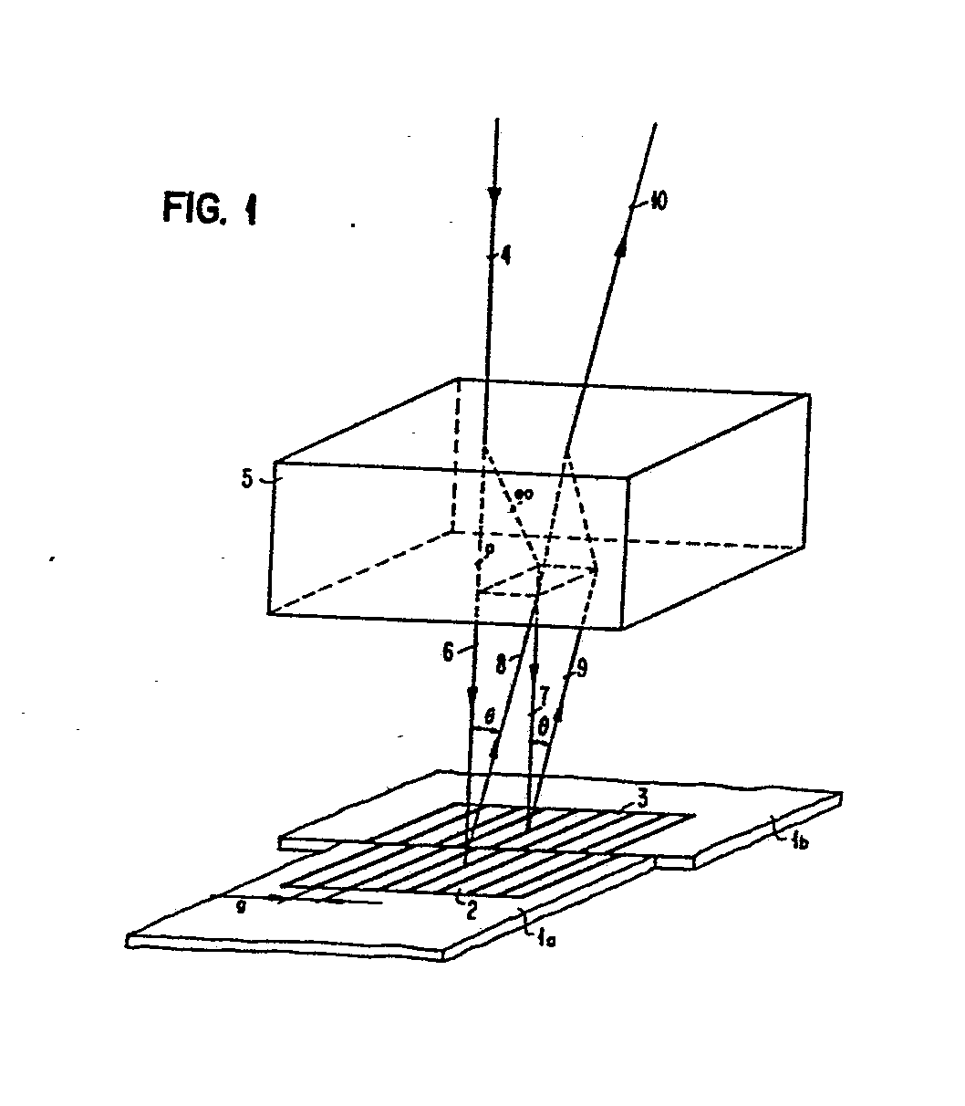
Description
Die Erfindung betrifft ein Verfahren zur optischen Distanzmessung nach dem Oberbegriff des Hauptanspruchs und Einrichtungen zur Durchführung des Verfahrens.The invention relates to a method for optical distance measurement according to the preamble of the main claim and devices for performing the method.
An die Messung von relativen oder absoluten Längen bzw. Verschiebungen werden in Wissenschaft und Technik immer höhere Genauigkeitsanforderungen gestellt. Ein Beispiel hierfür bietet die photolithographische Herstellung integrierter Schaltungen, bei der mittlerweile Strukturen mit einer Größenordnung von 1 Mikrometer aufgelöst werden müssen. Zur genauen Positionierung der Halbleiterscheiben (Wafer) vor der Belichtung muß daher die relative Lage von bereits vorhandenen Strukturen und Belichtungsmaske auf Bruchteile eines Mikrometers genau einstellbar sein; um einen hohen Produktionsdurchsatz zu ermöglichen, muß diese Einstellung außerdem sehr schnell erfolgen und darf an das Bedienungspersonal keine besonderen Anforderungen stellen.The measurement of relative or absolute lengths or displacements in science and technology is subject to ever higher accuracy requirements. An example of this is the photolithographic production of integrated circuits, in which structures with a size of 1 micron must now be resolved. For the exact positioning of the semiconductor wafers before exposure, the relative position of existing structures and exposure mask must therefore be adjustable to within a fraction of a micrometer; In order to enable a high production throughput, this setting must also be carried out very quickly and may not make any particular demands on the operating personnel.
Ähnliche Genauigkeitsanforderungen bestehen auch hinsichtlich der absoluten Messung von Längen, beispielsweise bei der Auswertung von Belichtungsmasken.Similar accuracy requirements also exist with regard to the absolute measurement of lengths, for example when evaluating exposure masks.
Die bisher hauptsächlich gebrauchten Meßverfahren mit visueller Beobachtung sind im Submikronbereich nicht mehr verwendbar, da sie zu stark von der subjektiven Einschätzung durch den Bediener abhängen. Diese Einschränkung gilt auch für die interferometrischen Verfahren, die mit visueller Beobachtung arbeiten.The measuring methods with visual observation that have been mainly used up to now can no longer be used in the submicron range, since they depend too much on the subjective assessment by the operator. This limitation also applies to the interferometric methods that work with visual observation.
Eine Erhöhung der Genauigkeit kann mit photoelektrischer Signalauswertung erreicht werden. Als Meßgröße wird dabei die Lichtintensität verwendet, beispielsweise deren sinusförmige Variation in einem interferometrischen Meßaufbau. Die bei der Auswertung dieses Kurvenverlaufes erreichbare Genauigkeit ist durch die starke Abhängigkeit der Lichtintensität von vielen Parametern des Meßaufbaus begrenzt; in vielen Fällen kann daher nur eine Nullpunktsbestimmung erfolgen und die gewünschte Meßgröße nur mit einer Genauigkeit bestimmt werden, die in der Größenordnung der verwendeten Lichtwellenlänge liegt.An increase in accuracy can be achieved with photoelectric signal evaluation. The measured variable is uses the light intensity, for example its sinusoidal variation in an interferometric measurement setup. The accuracy that can be achieved when evaluating this curve profile is limited by the strong dependence of the light intensity on many parameters of the measurement setup; in many cases, therefore, only a zero point determination can be carried out and the desired measured variable can only be determined with an accuracy which is in the order of magnitude of the light wavelength used.
Derartige interferometrische Meßsysteme sind beispielsweise so aufgebaut, daß die zu messende Länge Teil eines Michelson-Interferometeraufbaus bildet. Weitere interferometrische Verfahren, in denen die Phasenänderung von Licht ausgewertet wird, das an einem bewegten oder verschobenen optischen Gitter gebeugt wurde, sind in dem Artikel "A New Interferometric Alignment Technique" von D. C. Flenders und H. I. Smith in Applied Physics Letters, Band 31, Nr. 7 (Oktober 1977), Seite 426 und in der deutschen Offenlegungsschrift 24 31 166 beschrieben. Bei diesen Verfahren wird ebenfalls die Intensität der Interferenzerscheinungen ausgewertet, so daß sich die oben erwähnten Genauigkeitsbeschränkungen ergeben.Such interferometric measuring systems are constructed, for example, in such a way that the length to be measured forms part of a Michelson interferometer construction. Further interferometric methods in which the phase change of light which has been diffracted on a moving or shifted optical grating is evaluated are described in the article "A New Interferometric Alignment Technique" by DC Flenders and HI Smith in Applied Physics Letters, volume 31, no 7 (October 1977), page 426 and in
Die vorliegende Erfindung stellt sich daher die Aufgabe, ein Verfahren zur optischen Distanzmessung anzugeben, dessen Genauigkeit Bruchteile eines Mikrometers beträgt, das für eine Vielzahl von Meßaufgaben einsetzbar ist, schnell durchgeführt werden kann und dessen Ergebnisse weitgehend unabhängig von der Bedienungsperson sind; außerdem sollen Einrichtungen zur Durchführung des Verfahrens angegeben werden, die einen einfachen und stabilen Aufbau besitzen und an verschiedene Meßaufgaben angepaßt sind.The present invention therefore has as its object to provide a method for optical distance measurement, the accuracy of which is fractions of a micrometer, which can be used for a large number of measurement tasks, can be carried out quickly and the results of which are largely independent of the operator; In addition, facilities for carrying out the method are to be specified which have a simple and stable structure and are adapted to various measuring tasks.
Diese Aufgabe wird durch die in den Ansprüchen 1, 7, 9, 11 und 12 gekennzeichnete Erfindung gelöst; Ausgestaltungen der Erfindung sind in den Unteransprüchen gekennzeichnet.This object is achieved by the invention characterized in
Bei dem vorgeschlagenen Verfahren wird der Phasenunterschied zweier senkrecht zueinander polarisierter Teilbündel gemessen, der durch Wechselwirkung dieser Teilbündel mit gitterförmigen Strukturen auf dem Meßobjekt hervorgerufen wird. Zur genauen Bestimmung der Relativlage zweier Objekte werden diese jeweils mit einem optischen Gitter versehen; die von diesen Gittern ausgehenden gebeugten und senkrecht zueinander polarisierten Teilstrahlen werden optisch zu einem Strahl vereinigt und die Phasendifferenz gemessen, aus der sich die laterale Verschiebung der beiden Objekte ergibt. Zur absoluten Bestimmung der Verschiebung eines Objekts wird die Phasenverschiebung zwischen verschiedenen Beugungsordnungen gemessen, die an einem mit dem Objekt verbundenen Gitter bei dessen Verschiebung entsteht.In the proposed method, the phase difference between two perpendicularly polarized partial bundles is measured, which is caused by the interaction of these partial bundles with lattice-shaped structures on the measurement object. To determine the relative position of two objects, they are each provided with an optical grating; the partial beams that are diffracted and polarized perpendicular to one another from these gratings are optically combined into one beam and the phase difference is measured, from which the lateral displacement of the two objects results. For the absolute determination of the displacement of an object, the phase shift between different diffraction orders is measured, which occurs on a grating connected to the object during its displacement.
Zur Durchführung des Verfahrens wird eine Einrichtung vorgeschlagen, die aus einem Grundinstrument mit austauschbaren Meßköpfen besteht, die der jeweiligen Meßaufgabe angepaßt sind. Zur optischen Antastung des Meßobjekts und zur optischen Rekombination der Teilstrahlen werden verschiedene Meßköpfe mit doppelbrechenden Materialien angegeben. Die Signalauswertung erfolgt durch elektro-optische Kompensation des Phasenunterschieds in den wiedervereinigten Teilstrahlen in dem für alle Meßköpfe gleich ausgebildeten Auswertesystem.To carry out the method, a device is proposed which consists of a basic instrument with exchangeable measuring heads which are adapted to the respective measuring task. Various measuring heads with birefringent materials are specified for the optical probing of the measurement object and for the optical recombination of the partial beams. The signal is evaluated by electro-optical compensation of the phase difference in the reunited partial beams in the evaluation system, which is of the same design for all measuring heads.
Die mit diesem Verfahren erreichbare hohe Genauigkeit beruht auf der Erzeugung senkrecht zueinander polarisierter Teilstrahlen (Beugungsordnungen), deren Phasenunterschied mit außerordentlicher Genauigkeit durch elektro-optische Kompensation gemessen werden kann. Das Ausgangssignal der elektro-optischen Kompensationsvorrichtung stellt nämlich ein analoges Sägezahnsignal dar, das eine sehr gute Interpolation ermöglicht. Die gemeinsame Signalauswertung für verschiedene Meßköpfe zur Antastung des Meßobjekts stellt ein außerordentlich vielfältiges und einfach zu bedienendes Meßgerät dar.The high accuracy that can be achieved with this method is based on the generation of partial beams (diffraction orders) polarized perpendicular to one another, the phase difference of which can be measured with extraordinary accuracy by electro-optical compensation. The output signal of the electro-optical compensation device provides namely is an analog sawtooth signal that enables very good interpolation. The common signal evaluation for different measuring heads for probing the measuring object represents an extraordinarily diverse and easy-to-use measuring device.
Die erreichbare Meßgenauigkeit liegt bei 0,02 pm oder in der Größenordnung von 1/1000 der verwendeten Gitterkonstante; die Meßzeit liegt in der Größenordnung von Millisekunden und darunter.The achievable measuring accuracy is 0.02 pm or in the order of 1/1000 of the grating constant used; the measuring time is of the order of milliseconds and below.
Der optische Aufbau der Meßköpfe und der Auswerteeinrichtung ist relativ einfach; Auflösungs- und Fokussierprobleme treten hier nicht auf.The optical structure of the measuring heads and the evaluation device is relatively simple; Resolution and focusing problems do not occur here.
Ausführungsbeispiele der Erfindung werden nun anhand von Zeichnungen näher erläutert. Es zeigen:
- Fig. 1 eine schematische Darstellung des Meßprinzips für relative Verschiebungen unter Verwendung zweier Gitter
- Fign. 2A, B den schematischen Aufbau zweier Ausführungsformen der Meßeinrichtung zur Durchführung des Meßverfahrens nach Fig. 1
- Fig. 3 das Ausgangssignal eines elektro-optischen Phasenkompensators nach Fig. 2
- Fign. 4A, B, den schematischen Aufbau von drei Ausfüh-C rungsformen eines Meßkopfs zur absoluten Bestimmung der lateralen Verschiebung eines Gitters
- Fig. 5 die schematische Darstellung eines weiteren Meßkopfs zur Messung lateraler Verschiebungen eines Gitters
- Fig. 6 das Aufbauschema eines elektro-optischen Meßgeräts mit auswechselbaren Meßköpfen.
- Fig. 1 zeigt das Prinzip eines Verfahrens zur elektro-optischen Messung der relativen Verschiebung zweiter Objekte 1a, 1b gegeneinander. Auf jedem der Objekte ist eine als optisches Gitter
wirkende Struktur 2, 3 mit einer Gitterkonstanten g aufgebracht, beispielsweise durch Drucken, Ritzen, Prägen usw. Bei idealer Ausrichtung der beiden Objekte weisen diese Gitter mit paralleler Gitterrichtung keine Versetzung gegeneinander auf.
- Fig. 1 is a schematic representation of the measuring principle for relative displacements using two grids
- Fig. 2A, B show the schematic structure of two embodiments of the measuring device for carrying out the measuring method according to FIG. 1
- 3 shows the output signal of an electro-optical phase compensator according to FIG. 2
- Fig. 4A, B, the schematic structure of three embodiments of a measuring head for the absolute determination of the lateral displacement of a grating
- 5 shows the schematic representation of a further measuring head for measuring lateral displacements of a grating
- Fig. 6 shows the structure of an electro-optical measuring device with interchangeable measuring heads.
- 1 shows the principle of a method for electro-optical measurement of the relative displacement of two objects 1a, 1b relative to one another. A
structure 2, 3 acting as an optical grating with a grating constant g is applied to each of the objects, for example by printing, scratching, embossing, etc. With ideal alignment of the two objects, these grids with a parallel grating direction have no offset from one another.
Zur Beleuchtung der beiden Gitter 2, 3 mit zwei zueinander senkrecht polarisierten optischen Strahlenbündeln 6, 7 wird ein Lichtstrahl 4, z. B. ein Laserstrahl, auf einen optisch doppelbrechenden Kristall 5, z. B. Kalkspat, gerichtet und dort in zwei Teilstrahlen, einen ordentlichen (o) und einen außerordentlichen (eo) aufgespalten. Beide Teilstrahlen verlassen den doppelbrechenden Kristall 5 als zueinander paralelle Stahlenbündel 6, 7, deren Polarisationsrichtung senkrecht aufeinandersteht. Die Strahlenbündel 6, 7 überdecken mehrere Gitterperioden, werden an den beiden Gittern 2 bzw. 3 gebeugt und erzeugen mehrere Beugungsbündel verschiedener Ordnung; in Fig. 1 ist jeweils eine erste Eeugungsordnung bei den Bezugszeichen 8 bzw. 9 eingezeichnet (die dargestellten Beugungswinkel sind nicht maßstäblich).To illuminate the two
Die an den Gittern gebeugten Strahlungsbündel 8, 9 gelangen wieder in den doppelbrechenden Kristall 5; durch die unterschiedliche Brechung von ordentlichem und außerordentlichem Strähl werden die beiden reflektierten Bündel 8, 9 beim Austritt aus dem doppelbrechenden Kristall 5 wiedervereinigt und bilden ein gemeinsames Austrittsbündel 10 mit zwei senkrecht zueinander polarisierten Teilbündeln.The radiation beams 8, 9 diffracted at the gratings again enter the
Die Auswahl der Beugungsordnung, die im Austrittsbündel 10 beobachtet werden soll, erfolgt durch die Wahl der Beobachtungsrichtung entsprechend dem Beugungswinkel 6
- λ = Wellenlänge
- g = Gitterkonstante
- m = Beugungsordnung.
- λ = wavelength
- g = lattice constant
- m = diffraction order.
Aus Intensitätsgründen wird dabei die erste Beugungsordnung (m = 1) bevorzugt.For reasons of intensity, the first diffraction order (m = 1) is preferred.
Bei idealer Ausrichtung und gleicher Höhe der beiden Objekte 1a, 1b tritt keine Phasendifferenz zwischen den beiden gebeugten Bündeln 8, 9 und damit auch keine Phasendifferenz im Austrittsbündel 10 auf. Eine Verschiebung der beiden Gitter gegeneinander bewirkt dagegen eine Phasendifferenz φM. Diese Phasendifferenz kann durch elektro-optische Kompensation sehr genau gemessen werden und stellt somit ein Maß für die fehlerhafte Ausrichtung der beiden Gegenstände 1a, 1b dar. Einzelheiten dieser Phasenmessung werden anhand von Fig. 2 beschrieben.With the ideal alignment and the same height of the two objects 1a, 1b, there is no phase difference between the two diffracted bundles 8, 9 and therefore no phase difference in the
Das oben beschriebene Meßprinzip kann auch angewendet werden, um die genaue Lagereproduzierbarkeit von aufeinanderfolgenden Herstellschritten zu überprüfen, beispielsweise bei der Herstellung von Halbleitern mit mehreren Maskenbelichtungsschritten. In diesem Fall wird in jedem der zu untersuchenden Prozeßschritte eine Gitterstruktur 2 bzw. 3 auf ein einziges Halbleiterplättchen aufgebracht und die relative Lage dieser beiden Gitter nach dem oben beschriebenen Verfahren miteinander verglichen. Ein Versatz der Gitter (sogenannte Overlayfehler) kann dabei durch Justierfehler, Abbildungsfehler, Temperatureinflüsse bei der Herstellung usw. bedingt sein.The measuring principle described above can also be used to check the exact reproducibility of the bearing of successive manufacturing steps, for example in the production of semiconductors with several mask exposure steps. In this case, a
Fig. 2 zeigt den schematischen Aufbau eines Meßgeräts zur Durchführung des anhand von Fig. 1 beschriebenen Meßverfahrens; es besteht aus einem speziellen Meßkopf 20, in dem die Strahlaufteilung entsprechend Fig. 1 erfolgt, sowie aus Beleuchtungs- und Auswertevorrichtungen. Das Beleuchtungsbündel 4 wird von einem Laser 21 erzeugt, dem eine λ/2- . Platte 22, ein elektro-optischer Lichtmodulator 23, ein Soleil-Babinet-Kompensator 24 und ein optischer Strahlteiler 25 nachgeschaltet sind. Mit der 1/2-Platte 22 wird die Polarisationsrichtung des Laserlichts gedreht; im elektro-optischen Lichtmodulator 23 wird das einfallende Licht in zwei senkrecht zueinander polarisierte Komponenten aufgespalten und durch Anlegen einer periodischen elektrischen Spannung eine periodische Phasenverschiebung zwischen diesen beiden Komponenten erzeugt. Im Soleil-Babinet-Kompensator 3 kann die Phasendifferenz zwischen den beiden polarisierten Teilbündeln auf einen festen Anfangswert eingestellt werden.FIG. 2 shows the schematic structure of a measuring device for carrying out the measuring method described with reference to FIG. 1; it consists of a
Zur Vermeidung von Depolarisationseffekten bei der Reflektion am Strahlteiler 25 werden die den Modulator 23 verlassenden Teilbündel so orientiert, daß ihre Polarisationsrichtung parallel bzw. senkrecht zur Einfallsebene des Strahlteilers liegen. Die X/2-Platte 22 ist entsprechend unter einem Winkel von 45° zu diesen beiden Polarisationsrichtungen zu orientieren.To avoid depolarization effects during reflection at the
Nach dem Eintritt in den Meßkopf 20 wird das Laserbündel 4 auf die Oberfläche des Meßobjekts 1 (bzw. die beiden äneinanderstoßenden Objekte 1a, 1b) gebündelt. Beim Durchgang des fokussierten Lichtbündels durch eine doppelbrechende Platte 27 erfolgt eine Aufspaltung in zwei zueinander parallele Lichtbündel 6, 7 entsprechend Fig. 1, deren gegenseitiger Abstand von der Kristalldicke bestimmt wird. Die Einzelheiten der Strahlführung nach Fig. 1 sind in Fig. 2 nicht dargestellt. Das eine Lichtbündel trifft dabei auf das eine Gitter, das andere Lichtbündel auf das andere. Die Linse 5 wird so angepaßt, daß der Brennpunkt der Laserbündel auf dem Objekt etwa 10 Gitterperioden überdeckt. Das von den Gittern reflektierte und gebeugte Licht wird nach Rekombination durch den Kristall 27 in der Linse 26 kollimiert.After entering the measuring
Für die Phasenmessung wird vorzugsweise die +1. oder die -1. Beugungsordnung benutzt. Die Ausblendung der gewünschten Beugungsordnung erfolgt mit einer verschiebbaren Lochblende28, die im Strahlengang hinter der teildurchlässigen Platte 25 angebracht ist. Das reflektierte Austrittsbündel 10 gelangt hinter der Lochblende 28 durch einen Polarisator 29 zu einem Photodetektor 30.The +1 is preferably used for the phase measurement. or the -1. Diffraction order used. The desired diffraction order is masked out with a
Die Einzelheiten der elektro-optischen Phasenkompensation in einer Anordnung nach Fig. 2 sind in der deutschen Patentanmeldung P 28 51 750 beschrieben. Das Meßprinzip läßt sich folgendermaßen umreißen: Im elektro-optischen Modulator wird das linear polarisierte Licht des Laser 21 in zwei senkrecht zueinander polarisierte Teilstrahlen aufgespalten; abhängig vom Wert der am Modulator 23 anliegenden Spannung wird eine Komponente bezüglich der senkrecht dazu polarisierten Komponente verzögert. Die beiden senkrechten Teilbündel gelangen als ordentliche bzw. außerordentliche Strahlen in den doppelbrechenden Kristall 27 und erfahren bei Reflektion an gitterähnlichen Strukturen auf dem Objekt 1 eine unterschiedliche Phasenverschiebung. Die beiden senkrecht zueinander polarisierten Teilstrahlen im Austrittsbündel 10 setzen sich somit je nach Größe der relativen Phasenverschiebung zu linear, eliptisch oder zirkular polarisiertem Licht zusammen, so daß der bezüglich der linearen Polarisationsrichtung in Kreuzstellung angeordnete Analysator 29 kein, wenig oder viel Licht zum Detektor 30 gelangen läßt.The details of the electro-optical phase compensation in an arrangement according to FIG. 2 are described in the German
Bei Anlegen einer periodischen Spannung an den elektro-optischen Lichtkompensator 23 kann die Spannung bzw. die Phasendifferenz festgestellt werden, die erforderlich ist, um die Phasenverschiebung durch Reflektion an gegeneinander verschobenen Gitterstrukturen zu kompensieren. Der Nulldurchgang des Detektorsignals entspricht dieser kompensierenden Phasenverschiebung.When a periodic voltage is applied to the electro-
Die Phasenkompensation kann dabei sowohl auf der Beleuchtungsseite erfolgen als auch im Austrittsbündel. Fig. 2B zeigt eine gleichwertige Ausführungsform, in der der elektro-optische Lichtmodulator 23 und der Soleil-Babinet-Kompensator 24 zwischen Teilerplatte 25 und Analysator 29 geschaltet sind. Das Laserbündel 4 gelangt dabei direkt vom Laser'21 über Strahlteiler 25 in den Meßkopf 20. In den Teilfiguren 2A, B tragen gleiche Komponenten gleiche Bezugszeichen.The phase compensation can take place both on the lighting side and in the exit bundle. 2B shows an equivalent embodiment in which the electro-
Das Ausgangssignal der elektro-optischen Kompensationsvorrichtung nach Fig. 2A, B ist in Fig. 3 dargestellt. Das Ausgangssignal (die Kompensationsspannung U, die linear mit der Phasendifferenz zusammenhängt) steigt linear mit der Verschiebung der beiden Gitter relativ zueinander, so daß sich eine Sägezahnkurve mit der Gitterperiode g (im Beispiel g = 10 pm) ergibt. Die Interpolation zwischen zwei Zwischenwerten ist bei dem linearen Verlauf dieser Spannung mit großer Genauigkeit möglich.The output signal of the electro-optical compensation device according to FIGS. 2A, B is shown in FIG. 3. The output signal (the compensation voltage U , which is linearly related to the phase difference) increases linearly with the displacement of the two gratings relative to one another, so that a sawtooth curve with the grating period g (in the example g = 10 pm) results. The interpolation between two intermediate values is possible with great accuracy given the linear course of this voltage.
Eine eindeutige Messung der Phasendifferenz φm der beiden senkrecht zueinander polarisierten und an zueinander versetzten Gittern gebeugten Bündeln ist im Bereich![]()

![]()
Allgemein ist der Zusammenhang zwischen der Phasenverschiebung φM und der diese Phasenverschiebung bewirkenden Gitterverschiebung AX gegeben durch![]()
![]()
Durch den linearen Verlauf des Ausgangssignals ist die Phasenauflösung a der oben besprochenen elektro-optischen Phasenmeßmethode besser als
Bei Verwendung eines Gitters mit einer Gitterkonstanten g = 6 µm ergibt sich nach (4) eine Meßauflösung für den Versatz der beiden Gitter von![]()
![]()
Der Meßbereich beträgt dabei (AX) < 3 µm.The measuring range is (AX) <3 µm.
Zur Messung werden die beiden mit Gittern versehenen Objekte 1a, 1b (bzw. das Objekt 1 mit zwei aufgebrachten Gittern) zuerst so positioniert, daß beide aufgespaltenen Laserbündel zunächst auf das gleiche Gitter (z. B. Gitter 2) gerichtet sind. Bei dieser Stellung kann auch eine Phasendifferenz auftreten, beispielsweise durch Neigung der Objektoberfläche oder eine Verdrehung des Objekt. Diese Phasendifferenz wird gemessen und mit Hilfe des Babinet-Kompensators ein Phasenabgleich durchgeführt, so daß die resultierende Phasendifferenz O beträgt. Dann werden beide Teilbündel durch eine laterale Verschiebung oder durch'Einführung einer geneigten parallelen Glasplatte auf jeweils eines der Gitter 2, 3 gerichtet. Die dann gemessene Phasendifferenz entspricht der Versetzung der beiden Gitter.For the measurement, the two objects 1a, 1b provided with grids (or the
Bei dieser Meßmethode wurde vorausgesetzt, daß zwischen beiden Gittern keine Höhendifferenz besteht. Im anderen Fall muß zuerst die Höhendifferenz bestimmt werden, da diese eine zusätzliche Phasendifferenz bedingt. Dazu können die direkt reflektierten Lichtbündel (nullte Beugungsordnungen) herangezogen werden, die durch entsprechende Verschiebung der Lochblende 28 auswählbar sind. In einem ersten Schritt werden beide Bündel 6, 7 auf dasselbe Gitter gerichtet und die Phasendifferenz auf null abgestimmt; die Höhendifferenz wird in einem zweiten Meßschritt ermittelt, bei dem die Bündel 6, 7 auf verschiedene Gitter gerichtet werden.This method of measurement assumed that there was no height difference between the two grids. In the other case, the height difference must first be determined, since this requires an additional phase difference. For this purpose, the directly reflected light bundles (zeroth diffraction orders) can be used, which can be selected by appropriate displacement of the
Die bei Bewegung eines Gitters auftretende Phasenverschiebung zwischen verschiedenen Beugungsordnungen kann auch zur hochpräzisen, absoluten Längenmessung mit elektro-optischer Kompensation herangezogen werden. Der Phasenunterschied in zwei benachbarten Beugungsordnungen (z. B. der nullten und der ersten) ändert sich bei einer Verschiebung des Gitters relativ zum beleuchtenden Laserstrahlbündel gemäß der oben für den Fall zweier Gitter erläuterten Gleichung (4). Die Bestimmung dieses Phasenunterschieds mit dem oben besprochenen Kompensationsverfahren führt zu einer Auflösung von besser als 1/1000 Gitterkonstante.The phase shift between different diffraction orders that occur when a grating is moved can also be used for high-precision, absolute length measurement with electro-optical compensation. The phase difference in two adjacent diffraction orders (e.g. the zeroth and the first) changes when the grating is shifted relative to the illuminating laser beam according to equation (4) explained above for the case of two gratings. The determination of this phase difference with the compensation method discussed above leads to a resolution of better than 1/1000 grating constant.
In den Fign. 4A, 4B sind zwei Ausführungsformen von Meßköpfen 45 bzw. 46 dargestellt, mit denen ein Ausgangsstrahl 10 erzeugt werden kann, dessen beide senkrecht zueinander polarisierte Teilbündel eine elektro-optisch bestimmbare Phasendifferenz aufweisen. Zur Durchführung der Messung wird auf dem Objekt, dessen Verschiebung gemessen werden soll, oder auf dem Tisch, an dem das Objekt befestigt ist, ein winziger Gittermaßstab 43 angebracht. Dieses Gitter, das aus praktischen Gründen eine Gitterkonstante g von einigen um besitzen sollte, wird senkrecht mit einem linear polarisierten Laserbündel 4 beleuchtet; die reflektierten Lichtbündel in nullter Beugungsordnung (m = 0), und in erster Beugungsordnung (m = 1) werden durch doppelbrechende optische Bauelemente zu einem Ausgangsstrahl 10 vereinigt.In Figs. 4A, 4B show two embodiments of measuring heads 45 and 46, respectively, with which an
In Fig. 4A fällt das Beleuchtungsbündel 4 zuerst auf einen doppelbrechenden Kristall 40; die Polarisationsrichtung des Bündels 4 entspricht der des ordentlichen Strahls (o) im doppelbrechenden Kristall 40, so daß keine Strahlablenkung erfolgt. Der ordentliche Strahl gelangt dann durch eine Zentralöffnung in einem X/2-Plättchen 41 und den Mittelpunkt einer Linse 42 zum Gitter 43, wo er gebeugt wird. Die Linse 42 ist ungefähr im Abstand ihrer Brennweite vom Gitter 43 entfernt angeordnet. Der Brennfleck überdeckt einige Gitterperioden. Das nichtgebeugte Licht (Beugungsordnung m = O) wird senkrecht reflektiert und gelangt wiederum als ordentlicher Strahl in den doppelbrechenden Kristall 40. Das in erster Beugungsordnung gebeugte Licht wird unter einem Winkel 6 reflektiert, durch Linse 42 kollimiert und erfährt eine Drehung seiner Polarisationsebene um 90° im A/2-Plättchen 41; es gelangt somit als außerordentlicher Strahl in den doppelbrechenden Kristall 40, wird dort gebrochen und vereinigt sich am Ausgang des doppelbrechenden Kristalls 40 mit dem ordentlichen Strahl zum Ausgangsstrahl 10, der somit zwei senkrecht zueinander polarisierte Komponenten aufweist, die je nach Verschiebung des Gitters 43 eine mehr oder minder große relative Phasendifferenz aufweisen. Die Messung dieser Phasendifferenz durch elektro-optische Kom- pensation in einer Vorrichtung nach Fig. 2B ergibt wiederum das sägezahnförmige Ausgangssignal nach Fig. 3 (Die Auswertevorrichtung nach Fig. 2A kann hier nicht verwendet werden, da sonst das Eingangsbündel 4 zwei Polarisationsrichtungen aufweisen würde, die im doppelbrechenden Kristall aufgespalten wurden). Die Dicke des doppelbrechenden Kristalls 40 wird entsprechend dem Beugungswinkel φ so gewählt, daß an seiner Austrittsfläche die gewünschte Strahlrekombination auftritt.In Fig. 4A, the
Ein mit Fig. 4A gleich wirkender Meßkopf 46 ist in Fig. 4B dargestellt; zwischen doppelbrechendem Kristall 40 und Gitter 43 ist dabei ein Rochon-Prisma 48 angebracht, sowie ein λ/2-Plättchen 49, das jedoch nur vom einfallenden und vom senkrecht reflektierten Licht durchsetzt wird. Der senkrecht zurückgeworfene Strahl nullter Ordnung gelangt nach der wiederholten Drehung seiner Polarisationsrichtung um 90 im X/2-Plättchen 49 unabgelenkt durch das Rochon-Prisma und den doppelbrechenden Kristall 40. Die erste Beugungsordnung dagegen, die mit der optischen Achse den Winkel θ einschließt, behält ihre Polarisationsrichtung bei und durchsetzt das Rochon-Prisma 48 als außerordentlicher Strahl. Der Ablenkwinkel des Rochon-Prismas wird dabei gleich dem Beugungswinkel 8 gewählt, so daß der aus dem Rochon-Prisma austretende Strahl zur optischen Achse parallel ist und als außerordentlicher Strahl in den doppelbrechenden Kristall 40 eintritt. Bei geeignet gewählter Dicke des Kristalls werden die beiden Strahlen den Kristall 40 als Ausgangsstrahl 10 verlassen und eine Phasendifferenz entsprechend der Verschiebung von Gitter 43 aufweisen.A measuring head 46 which acts identically with FIG. 4A is shown in FIG. 4B; A
Eine weitere Ausführungsform eines Meßkopfs zur Messung lateraler Gitterverschiebungen ist in Fig. 4C dargestellt; er zeichnet sich durch eine erhöhte Empfindlichkeit aus.Another embodiment of a measuring head for measuring lateral grid displacements is shown in FIG. 4C; it is characterized by an increased sensitivity.
Das Lichtbündel 401 eines Lasers fällt auf ein Wollaston-Prisma 402, wo es in zwei senkrecht zueinander polarisierte Teilstrahlen aufgespalten wird, die nach Reflektion an einem Strahlteiler 403 und Durchgang durch eine Linse 404 als Einfallsbündel 405 und 406 unter einem Einfallswinkel 6 zusammen auf dem Meßgitter 43 auftreffen. Der Winkel 6 ist entsprechend der ersten Beugungsordnung gewählt, so daß die +1. und die -1. Beugungsordnung senkrecht zum Meßgitter (in Richtung 407) abgebeugt werden.The
Die aus den Bündeln 405, 406 entstehenden Beugungsordnungen bleiben weiterhin senkrecht zueinander polarisiert und weisen bei gleicher Gitterverschiebung einen Phasenunterschied auf, der dem doppelten des in Gleichung (4) angegebenen Werts entspricht (Gleichung (4) bezieht sich auf zwei benachbarte Beugungsordnungen). Das Ausgangsbündel 408 verläßt den Meßkopf durch den Strahlteiler 403 und kann in üblicher Weise ausgewertet werden.The diffraction orders resulting from the
In den Ausführungsbeispielen nach Fig. 4 werden Meß- und Referenzstrahl durch den auf dem Gitter auftreffenden Laserstrahl am gleichen Ort des Gittermaßstabs erzeugt. Dadurch ist dieses Meßverfahren weitgehend unempfindlich gegen Brechungsindexänderungen durch Druck oder Temperaturschwankungen. Außerdem ist das Verfahren unempfindlich gegenüber Abstandsschwankungen des Gittermaßstabs relativ zum Meßkopf. Die Meßanordnungen nach Fig. 4 können auch zur Messung von Relativverschiebungen in der nach Fig. 1 beschriebenen Art verwendet werden; dazu wird der Meßpunkt nacheinander auf die Gitter gerichtet und die relative Phasendifferenz für beide Stellungen ermittelt. Hierbei verfälschen geringe Höhendifferenzen der Gitter die Meßergebnisse für die laterale Verschiebung nicht. Dieselben Vorteile bietet auch die im folgenden besprochene Meßanordnung nach Fig. 5.In the exemplary embodiments according to FIG. 4, measuring and reference beams are generated by the laser beam striking the grating at the same location on the grating scale. As a result, this measuring method is largely insensitive to changes in the refractive index due to pressure or temperature fluctuations. In addition, the method is insensitive to distance fluctuations on the grating scale relative to the measuring head. 4 can also be used to measure relative displacements in the manner described in FIG. 1; For this purpose, the measuring point is directed one after the other onto the grating and the relative phase difference for both positions is determined. Small differences in the height of the grids do not falsify the measurement results for the lateral displacement. The measuring arrangement according to FIG. 5 discussed below offers the same advantages.
Ein weiteres Ausführungsbeispiel eines optischen Meßkopfs 50 mit doppelbrechenden Elementen zur Messung lateraler Verschiebungen mit Hilfe einer am Meßobjekt angebrachten gitterähnlichen Struktur ist in Fig. 5 dargestellt; er entspricht funktionsmäßig den Meßköpfen nach Fig. 4. Das zur Beleuchtung verwendete linear polarisierte Laserlichtbündel 4 tritt in den Meßkopf 50 durch eine wahlweise vorhandene Linse 51 als ordentlicher Strahl 55 in einen doppelbrechenden Kristall 52 ein, den es unabgelenkt durchsetzt (der in Fig. 5 eingezeichnete außerordentliche (eo) Eintrittsstrahl tritt bei dieser Betriebsweise nicht auf). Zwischen dem doppelbrechenden Kristall 52 und dem Meßobjekt mit Gitter 43 sind ein Wollaston-Prisma 53a, 53b und ein 3X/4-Plättchen 54 vorgesehen. Das Wollaston-Prisma enthält längs der optischen Achse eine Bohrung, in der der Mittelpunktsstrahl verläuft; das 3A/4-Plättchen ist im selben Bereich der optischen Achse so ausgedünnt, daß es für den Mittelpunktsstrahl 55 als X/4-Plättchen wirkt.Another embodiment of an
Der aus dem doppelbrechenden Kristall 52 austretende, ordentliche Mittelpunktsstrahl trifft senkrecht auf die Gitterstruktur 43 auf, und das direkt reflektierte Licht (in nullter Beugungsordnung) läuft als Mittelpunktsstrahl wieder zurück; beim zweimaligen Durchgang durch das X/4-Plättchen in der Mitte der Platte.54 wird die Polarisationsebene des Lichtes nullter Beugungsordnung um 90° gedreht, so daß der reflektierte Strahlanteil im doppelbrechenden Kristall 52 als außerordentlicher Strahl 57 verläuft und gebrochen wird.The normal center beam emerging from the
Das Licht höherer Beugungsordnungen verläßt dagegen Gitter 43 unter einem Winkel ![]()
![]()
![]()
![]()
Der in Fig. 5 dargestellte Meßkopf 50 läßt sich außerdem ohne konstruktive Änderungen zur Durchführung eines Meßverfahrens für vertikale Längenänderungen oder Stufenhöhen verwenden, wie es in der deutschen Patentanmeldung P 29 25 117.0 beschrieben ist. Dort wird das Meßobjekt, dessen Oberflächenprofil bestimmt werden soll, mit zwei senkrecht zueinander polarisierten Teilbündeln beaufschlagt, deren Achsen einen Winkel miteinander einschließen und die beide auf einem gemeinsamen Bereich der zu untersuchenden Oberfläche auftreffen; die reflektierten Strahlen werden dann zur Bildung von Interferenzen wiedervereinigt. In der erwähnten Patentanmeldung werden die beiden Teilstrahlen durch Aufspaltung in einem doppelbrechenden Kristall erzeugt und als Mittelpunkts- bzw. Randstrahlen durch eine Sammellinse auf das Untersuchungsobjekt fokussiert; der Winkel zwischen den beiden Teilstrahlen bestimmt sich aus der Strahlaufspaltung und der Brennweite der Sammellinse. Diese Einrichtung hat den Nachteil, daß das eine Teilbündel exakt als Mittelpunktsstrahl durch die Sammellinse geführt werden muß, da sonst kein exakt definierter Winkel gewährleistet ist.The measuring
Diese hohen Anforderungen an die Justiergenauigkeit werden bei dem Meßkopf nach Fig. 5 vermieden, wenn als.beleuchten- de Teilstrahlen die Strahlen 55 und 56 verwendet werden, die bei der Aufspaltung eines Laserbündels 4 geeigneter Polarisationsrichtung im doppelbrechenden Kristall 52 auftreten. Der ordentliche Strahlenteil 55 wird wie im vorigen Beispiel als Mittelpunktsstrahl geführt, der außerordentliche Anteil (eo) des Beleuchtungsbündels 4 wird in der doppelbrechenden Platte 52 abgelenkt, gelangt in das Wollaston-Prisma 53a, wo er erneut so abgelenkt wird, daß er auf der Oberfläche des Meßobjekts mit dem Mittelpunktsstrahl 65 unter dem gewünschten Winkel 6 zusammentrifft. Das Strahlenbündel 56 wird am Meßpunkt, z. B. einer Stufe, nach dem Reflektionsgesetz reflektiert und im Wollaston-Prisma 53b wieder zu einem achsenparallelen Bündel abgelenkt. Das schräg auf dem Objekt 43 auftreffende Bündel durchläuft vor und nach der Reflektion jeweils den Teil der Platte 54, deren Dicke einem 3X/4-Plättchen entspricht, so daß insgesamt eine Drehung der Polarisationsebene um 90° erfolgt; der Strahl 58 verläuft also in der doppelbrechenden Platte 52 als ordentlicher Strahl und rekombiniert mit dem senkrecht reflektierten Mittelpunktsstrahl 65, der beim zweimaligen Durchgang durch die X/4-Platte im Mittelpunktsbereich der Platte 54 eine Drehung der Polarisationsebene um 90° erfuhr und deshalb nach der Reflektion als außerordentlicher Strahl 57 in der doppelbrechenden Platte 52 verläuft.These high demands on the adjustment accuracy are avoided in the measuring head according to FIG. 5 if the
Bei der Anordnung nach Fig. 5 wird der Winkel 8 zwischen den beiden Strahlen 55 und 56 nur durch die Kenngrößen der doppelbrechenden Elemente 52, 53 bestimmt, die mechanisch fest miteinander verbunden sind (beispielsweise verkittet). Damit treten die oben erwähnten Justierschwierigkeiten oder Änderungen des Winkels während der Messung nicht mehr auf.5, the angle 8 between the two
Für die bisher beschriebenen elektro-optischen Meßköpfe 20, 45, 46, 50 kann zur Auswertung der zwischen den beiden polarisierten Teilstrahlen erzeugten Phasendifferenz ein einziges elektro-optisches Meßgerät verwendet werden. Fig. 6 zeigt den schematischen Aufbau eines derartigen universellen, modularen elektro-optischen Meßgeräts.For the electro-optical measuring heads 20, 45, 46, 50 described so far, the evaluation between the two po Larized partial beams generated phase difference, a single electro-optical measuring device can be used. Fig. 6 shows the schematic structure of such a universal, modular electro-optical measuring device.
Das Ausgangsbündel 4 eines Lasers 60 wird über einen Umlenkspiegel 61 auf einen Strahlteiler (z. B. Würfel 62) gegeben und gelangt dann in den jeweiligen Meßkopf, der in eine gemeinsam benutzbare Halterung 63 eingesetzt ist. Das auf die Phasendifferenz zu analysierende Ausgangsbündel 10 tritt durch eine Lochblende 64 in einen Babinet-Soleil-Kompensator 65 und gelangt von dort in einen elektro-optischen Modulator 66, einen Analysator 67 und einen Detektor 68. Soll in dieses Meßgerät ein Meßkopf nach Fig. 4C eingesetzt werden, muß der Strahlteiler 62 abgenommen werden.The
Die Anzahl der mit dem Meßgerät nach Fig. 6 verwendbaren Meßköpfe ist nicht auf die hier erwähnten beschränkt; es kann eine Vielzahl weiterer Meßköpfe angeschlossen werden, wie sie beispielsweise in den deutschen Patentanmeldungen P 28 51 750.2 und der obenerwähnten P 29 25 117.0 beschrieben sind; wichtig ist nur, daß in dem jeweiligen Meßkopf jeweils zwei zueinander senkrecht polarisierte Teilstrahlen erzeugt werden, die eine vom Meßvorgang beeinflußte Phasendifferenz aufweisen. Damit stellt die Meßeinrichtung nach Fig. 6 ein außerordentlich vielseitiges Instrumentarium für einen sehr großen Bereich hochgenauer optischer Messungen zur Verfügung, beispielsweise Längenmessungen relativer oder absoluter Art, Oberflächenuntersuchungen wie Stufen, Krümmungen, Steigungen, Kantenuntersuchungen usw. Bedingt durch die große Geschwindigkeit des Kompensationsverfahrens ergibt sich eine hohe Meßgeschwindigkeit; das Verfahren kann auch vollautomatisch durchgeführt werden.The number of measuring heads that can be used with the measuring device according to FIG. 6 is not limited to the ones mentioned here; a large number of further measuring heads can be connected, as described, for example, in German
Zur Erhöhung der Meßauflösung können anstelle der bisher erwähnten niedrigen Beugungsordnungen auch höhere Ordnungen herangezogen werden.In order to increase the measurement resolution, higher orders can also be used instead of the previously low diffraction orders.
Die hier vorgeschlagenen Verfahren und Einrichtungen eignen sich auch zur genauen Ausmessung zweidimensionaler Muster, von Interferenz- und Moirestreifen.The methods and devices proposed here are also suitable for the precise measurement of two-dimensional patterns, of interference and moiré fringes.
Die in der Beschreibung verwendeten Ausdrücke "Strahlen", "Teilstrahlen" sind der Kürze halber anstelle der genaueren Bezeichnungen "Strahlenbündel" und "Teilstrahlenbündel" gebraucht.For the sake of brevity, the terms "rays", "partial rays" used in the description are used instead of the more precise designations "ray bundle" and "partial ray bundle".
Claims (18)
dadurch gekennzeichnet,
daß durch Beugung an mindestens einem mit dem Meßobjekt verbundenen optischen Gitter (Meßgitter 2, 3, 43) zwei zueinander senkrecht polarisierte Teilstrahlen (z. B. 8, 9) gleicher oder verschiedener Beugungsordnung erzeugt werden, und daß die bei Verschiebung eines Gitters hervorgerufene Phasendifferenz der Teilstrahlen durch elektro-optische Phasenkompensation der collinear gemachten Teilstrahlen bestimmt wird.1. Method for optical distance measurement by determining the phase shift of light when it is diffracted on shifted optical gratings,
characterized,
that by diffraction at least one optical grating (measuring grating 2, 3, 43) connected to the measurement object, two mutually perpendicularly polarized partial beams (e.g. 8, 9) of the same or different diffraction order are generated, and that the phase difference caused when a grating is shifted the partial beams is determined by electro-optical phase compensation of the collinearly made partial beams.
daß zwei gegeneinander verschiebbare Meßgitter (2, 3; Fig. 1) verwendet werden und daß die Phasendifferenz zwischen zwei Teilstrahlen (8, 9) gleicher Beugungsordnung elektro-optisch bestimmt wird.2. The method according to claim 1, characterized in that
that two mutually displaceable measuring grids (2, 3; Fig. 1) are used and that the phase difference between two partial beams (8, 9) of the same diffraction order is determined electro-optically.
daß jedes der Meßgitter (2, 3) mit einem polarisierten - Lichtstrahl (6, 7) beleuchtet wird und daß die Polarisationsrichtungen dieser Strahlen senkrecht aufeinanderstehen.3. The method according to claim 2, characterized in
that each of the measuring grids (2, 3) is illuminated with a polarized light beam (6, 7) and that the polarization directions of these beams are perpendicular to one another.
daß ein Meßgitter (43) verwendet wird und daß die Phasendifferenz zwischen zwei'Teilstrahlen verschiedener Beugungsordnungen elektro-optisch bestimmt wird.4. The method according to claim 1, characterized in
that a measuring grid (43) is used and that the phase difference between two partial beams different diffraction orders is determined electro-optically.
daß das Meßgitter (43) mit einem polarisierten Lichtstrahl ((o)-Strahl in Fig. 4A, B) beleuchtet wird und daß die Polarisation einer ausgewählten Beugungsordnung nach der Beugung um 900 gedreht wird.5. The method according to claim 4, characterized in
that the measuring grid (43) is illuminated with a polarized light beam ((o) beam in Fig. 4A, B) and that the polarization is rotated a selected diffraction order after diffraction by 90 0th
daß das Meßgitter (43) symmetrisch mit zwei senkrecht zueinander polarisierten Lichtstrahlen (405, 406) gleichen Einfallswinkels (e) beleuchtet wird und daß die Phasendifferenz zwischen symmetrischen Beugungsordnungen beider Bündel (z. B. +1. und -1.) bestimmt wird.6. The method according to claim 4, characterized gekennziechnet,
that the measuring grating (43) is illuminated symmetrically with two perpendicularly polarized light beams (405, 406) of the same angle of incidence (e) and that the phase difference between symmetrical diffraction orders of the two beams (e.g. +1 and -1) is determined.
dadurch gekennzeichnet,
daß eine doppelbrechende Platte (5 bzw. 27) zur Aufspaltung eines Eingangsstrahls (4) und zur Rekombination der an zwei mit den Meßobjekten (1a, 1b) verbundenen Gittern (2, 3) in gleicher Beugungsordnung gebeugten Teilstrahlen (8, 9).7. Device for performing the method according to claim 3,
characterized,
that a birefringent plate (5 or 27) for splitting an input beam (4) and for recombining the partial beams (8, 9) diffracted in the same diffraction order on two gratings (2, 3) connected to the measurement objects (1a, 1b).
daß vor der doppelbrechenden Platte (27) eine Sammellinse (26) zur Fokussierung der Eingangsstrahlen (4) auf das Meßobjekt (1) vorgesehen ist.8. Device according to claim 7, characterized in
that a collecting lens (26) is provided in front of the birefringent plate (27) for focusing the input beams (4) onto the measurement object (1).
dadurch gekennzeichnet,
daß in Richtung des Eingangsstrahls (4) eine doppelbrechende Platte (40), ein X/2-Plättchen (41) mit einem Zentralloch und eine Linse (42) angeordnet sind, daß der Abstand der Linse (42) vom Meßgitter (43) ihrer Brennweite entspricht und
daß die Dicke der doppelbrechenden Platte (40) so gewählt ist, daß das Beugungsbündel nullter und erster Ordnung an ihrer Austrittsfläche rekombinieren.9. Device for performing the method according to claim 5,
characterized,
that a birefringent plate (40), an X / 2 plate (41) with a central hole and a lens (42) are arranged in the direction of the input beam (4), that the distance of the lens (42) from the measuring grid (43) of their Corresponds to focal length and
that the thickness of the birefringent plate (40) is chosen so that the zero and first order diffraction beams recombine at their exit surface.
dadurch gekennzeichnet,
daß in Richtung des Eingangsstrahls (4) eine doppelbrechende Platte (40), ein Rochon-Prisma (48) und eine X/2-Platte (49) angeordnet sind,
daß das in erster Ordnung gebeugte Bündel vor seinem Eintritt in den doppelbrechenden Kristall (40) das Rochon-Prisma (48) durchläuft und dabei zu einem achsenparallelen Bündel gebrochen wird und
daß die Dicke der doppelbrechenden Platte (40) so gewählt ist, daß die Beugungsbündel nullter und erster Ordnung an ihrer Austrittsfläche rekombinieren.10. Device for performing the method according to claim 5,
characterized,
that a birefringent plate (40), a Rochon prism (48) and an X / 2 plate (49) are arranged in the direction of the input beam (4),
that the bundle bent in the first order passes through the Rochon prism (48) before it enters the birefringent crystal (40) and is thereby broken into an axially parallel bundle and
that the thickness of the birefringent plate (40) is chosen so that the zero and first order diffraction beams recombine at their exit surface.
dadurch gekennzeichnet,
daß die Eingangsstrahlen (401) in einem Wollaston-Prisma (402) aufgespalten und die beiden Teilstrahlen durch eine Sammellinse (404) unter symmetrisch gleichen Einfallswinkeln auf dem Meßgitter (43) so vereinigt werden, daß der Einfallswinkel (8) dem Beugungswinkel erster Ordnung entspricht und daß als Ausgangsstrahlen (408) die Beugungsbündel +1. und -1. Ordnung dienen.11. Device for performing the method according to claim 6,
characterized,
that the input beams (401) split in a Wollaston prism (402) and the two partial beams are combined by a converging lens (404) at symmetrically identical angles of incidence on the measuring grating (43) so that the angle of incidence (8) corresponds to the first-order diffraction angle and that the diffraction beams +1 as output beams (408). and -1. Serve order.
dadurch gekennzeichnet,
daß das Eingangsbündel (4) eine doppelbrechende Platte (52), ein Wollaston-Prisma (53) mit Zentralloch und eine 3X/4-Platte (54) mit ausgedünntem, einer X/4-Platte entsprechendem Zentralteil durchläuft und daß der Ablenkwinkel des Wollaston-Prismas (53) entsprechend dem Beugungswinkel (0) erster Ordnung gewählt ist.12. Device for interferometric distance measurement with electro-optical compensation of the phase difference between two sub-beams polarized perpendicular to one another, in particular for carrying out the method according to claim 3.
characterized,
that the input bundle (4) passes through a birefringent plate (52), a Wollaston prism (53) with a central hole and a 3X / 4 plate (54) with a thinned-out central part corresponding to an X / 4 plate, and that the deflection angle of the Wollaston -Prism (53) is selected according to the first-order diffraction angle (0).
dadurch gekennzeichnet,
daß in Richtung des Eingangsstrahls (4) vor der doppelbrechenden Platte (52) eine Sammellinse (51) angeordnet ist.13. Device according to claim 12,
characterized,
that a converging lens (51) is arranged in the direction of the input beam (4) in front of the birefringent plate (52).
dadurch gekennzeichnet,
daß die Polarisation des Eingangsstrahls (4) der Polarisation des ordentlichen Strahls im doppelbrechenden Kristall (52) entspricht.14. A method for operating the device according to claim 12 or 13,
characterized,
that the polarization of the input beam (4) corresponds to the polarization of the ordinary beam in the birefringent crystal (52).
dadurch gekennzeichnet,
daß die Polarisation des Eingangsstrahls (4) so gewählt ist, daß in der doppelbrechenden Platte (52) ein ordentlicher (o) und ein außerordentlicher (eo) Strahl entstehen.15. A method for operating the device according to claim 12 or 13,
characterized,
that the polarization of the input beam (4) is selected so that in the birefringent plate (52) an ordinary (o) and an extraordinary (eo) ray arise.
daß das Eingangsbündel (4) von einem Laser (21, Fig. 2 bzw. 60 Fig. 6) über einen Strahlteiler (25 bzw. 62) geliefert wird und
daß das Ausgangsbündel (10) durch den Strahlteiler (25 bzw. 62) über eine Ausgangsblende (28 bzw. 64), einen Babinet-Soleil-Kompensator (24 bzw. 65), einen elektro-optischen Modulator (23 bzw. 66) und einen Analysator (29 bzw. 67) in einen Lichtdetektor (10 bzw. 68) gelangt.16. Device according to one of claims 7 to 13, characterized in
that the input beam (4) is supplied by a laser (21, Fig. 2 or 60 Fig. 6) via a beam splitter (25 or 62) and
that the output beam (10) through the beam splitter (25 or 62) via an output aperture (28 or 64), a Babinet-Soleil compensator (24 or 65), an electro-optical modulator (23 or 66) and an analyzer (29 or 67) enters a light detector (10 or 68).
daß eine gemeinsame Aufnahmevorrichtung (h3) für Meßeinrichtungen nach einem der Ansprüche 7 bis 13 vorgesehen ist.17. The device according to claim 16, characterized in
that a common receiving device (h3) for measuring devices according to one of claims 7 to 13 is provided.
daß das Eingangsbündel (4) von einem Laser (21) über eine X/2-Platte (22, Fig. 2A) einen elektro-optischen Modulator (23), einen Babinet-Soleil-Kompensator (24) und einen Strahlteiler (25) geliefert wird und daß das Ausgangsbündel (10) durch den Strahlteiler (25) über einen Analysator (29) zu einem Detektor (30) gelangt.18. Device according to one of claims 7 or 8 or for performing the method according to claim 15, characterized in that
that the input beam (4) from a laser (21) via an X / 2 plate (22, Fig. 2A) an electro-optical modulator (23), a Babinet-Soleil compensator (24) and a beam splitter (25) is delivered and that the output beam (10) passes through the beam splitter (25) via an analyzer (29) to a detector (30).
Priority Applications (4)
| Application Number | Priority Date | Filing Date | Title |
|---|---|---|---|
| EP80104529A EP0045321B1 (en) | 1980-07-31 | 1980-07-31 | Method and device for optical distance measurement |
| DE8080104529T DE3071858D1 (en) | 1980-07-31 | 1980-07-31 | Method and device for optical distance measurement |
| JP56107162A JPS5750611A (en) | 1980-07-31 | 1981-07-10 | Optical range measurement |
| US06/694,576 US4577968A (en) | 1980-07-31 | 1985-01-24 | Method and arrangement for optical distance measurement |
Applications Claiming Priority (1)
| Application Number | Priority Date | Filing Date | Title |
|---|---|---|---|
| EP80104529A EP0045321B1 (en) | 1980-07-31 | 1980-07-31 | Method and device for optical distance measurement |
Publications (3)
| Publication Number | Publication Date |
|---|---|
| EP0045321A2 true EP0045321A2 (en) | 1982-02-10 |
| EP0045321A3 EP0045321A3 (en) | 1984-09-05 |
| EP0045321B1 EP0045321B1 (en) | 1986-12-10 |
Family
ID=8186738
Family Applications (1)
| Application Number | Title | Priority Date | Filing Date |
|---|---|---|---|
| EP80104529A Expired EP0045321B1 (en) | 1980-07-31 | 1980-07-31 | Method and device for optical distance measurement |
Country Status (4)
| Country | Link |
|---|---|
| US (1) | US4577968A (en) |
| EP (1) | EP0045321B1 (en) |
| JP (1) | JPS5750611A (en) |
| DE (1) | DE3071858D1 (en) |
Cited By (3)
| Publication number | Priority date | Publication date | Assignee | Title |
|---|---|---|---|---|
| EP0112399B1 (en) * | 1982-12-20 | 1987-03-11 | Ibm Deutschland Gmbh | Interferential measuring method for surfaces |
| CN108604065A (en) * | 2015-12-23 | 2018-09-28 | Asml荷兰有限公司 | Method for measurement, target and substrate |
| CN109661559A (en) * | 2016-09-28 | 2019-04-19 | 科磊股份有限公司 | Optical near-field measurement |
Families Citing this family (32)
| Publication number | Priority date | Publication date | Assignee | Title |
|---|---|---|---|---|
| US4703434A (en) * | 1984-04-24 | 1987-10-27 | The Perkin-Elmer Corporation | Apparatus for measuring overlay error |
| DE3682675D1 (en) * | 1986-04-29 | 1992-01-09 | Ibm Deutschland | INTERFEROMETRIC MASK SUBSTRATE ALIGNMENT. |
| NL8601278A (en) * | 1986-05-21 | 1987-12-16 | Philips Nv | DEVICE FOR DETECTING AN ENLARGEMENT ERROR IN AN OPTICAL IMAGE SYSTEM. |
| FR2615280B1 (en) * | 1987-05-11 | 1996-07-19 | Canon Kk | DEVICE FOR MEASURING THE MOTION DISTANCE RELATIVE OF TWO MOBILE OBJECTS IN RELATION TO THE OTHER |
| FR2615281B1 (en) * | 1987-05-11 | 1996-08-23 | Canon Kk | DEVICE FOR MEASURING A RELATIVE MOTION DISTANCE OF TWO MOBILE OBJECTS IN RELATION TO ONE ANOTHER |
| EP0313681A1 (en) * | 1987-10-30 | 1989-05-03 | Ibm Deutschland Gmbh | Phase-sensitive interferometric mask-wafer alignment |
| DE69133626D1 (en) * | 1990-03-27 | 2010-03-11 | Canon Kk | Measuring method and device |
| US5545039A (en) * | 1990-04-10 | 1996-08-13 | Mushabac; David R. | Method and apparatus for preparing tooth or modifying dental restoration |
| US5343391A (en) * | 1990-04-10 | 1994-08-30 | Mushabac David R | Device for obtaining three dimensional contour data and for operating on a patient and related method |
| US5257184A (en) * | 1990-04-10 | 1993-10-26 | Mushabac David R | Method and apparatus with multiple data input stylii for collecting curvilinear contour data |
| US5569578A (en) * | 1990-04-10 | 1996-10-29 | Mushabac; David R. | Method and apparatus for effecting change in shape of pre-existing object |
| US5224049A (en) * | 1990-04-10 | 1993-06-29 | Mushabac David R | Method, system and mold assembly for use in preparing a dental prosthesis |
| US5347454A (en) * | 1990-04-10 | 1994-09-13 | Mushabac David R | Method, system and mold assembly for use in preparing a dental restoration |
| US5562448A (en) * | 1990-04-10 | 1996-10-08 | Mushabac; David R. | Method for facilitating dental diagnosis and treatment |
| US5133599A (en) * | 1991-01-02 | 1992-07-28 | Zygo Corporation | High accuracy linear displacement interferometer with probe |
| CA2078732A1 (en) * | 1991-09-27 | 1993-03-28 | Koichi Sentoku | Displacement measuring device and displacement measuring method |
| JPH06137830A (en) * | 1992-10-23 | 1994-05-20 | Canon Inc | Interference measuring method and interference measuring apparatus |
| JP2746178B2 (en) * | 1995-02-15 | 1998-04-28 | 双葉電子工業株式会社 | Measurement device interpolation circuit |
| US6407815B2 (en) | 1998-07-02 | 2002-06-18 | Sony Precision Technology Inc. | Optical displacement measurement system |
| US6020966A (en) * | 1998-09-23 | 2000-02-01 | International Business Machines Corporation | Enhanced optical detection of minimum features using depolarization |
| EP1026550B1 (en) * | 1999-02-04 | 2005-06-08 | ASML Netherlands B.V. | Lithographic projection apparatus |
| US6469793B1 (en) * | 1999-08-10 | 2002-10-22 | Svg Lithography Systems, Inc. | Multi-channel grating interference alignment sensor |
| DE10025461A1 (en) * | 2000-05-23 | 2001-12-06 | Mahr Gmbh | Measurement device, especially for measuring workpiece surface roughness and/or contour has probe with diffraction grating for +1, 0 and -1 orders |
| US20050010310A1 (en) * | 2003-07-11 | 2005-01-13 | Touzov Igor Victorovich | Method of alignment for precision tools. |
| US20090147265A1 (en) * | 2004-11-22 | 2009-06-11 | Koninklijke Philips Electronics, N.V. | Detection system for detecting translations of a body |
| US7636165B2 (en) * | 2006-03-21 | 2009-12-22 | Asml Netherlands B.V. | Displacement measurement systems lithographic apparatus and device manufacturing method |
| FR2933494B1 (en) * | 2008-07-01 | 2010-09-03 | Commissariat Energie Atomique | DEVICE FOR OPTICALLY CHARACTERIZING AN OBJECT OF VERY SMALL DIMENSIONS |
| DE102010063253A1 (en) * | 2010-12-16 | 2012-06-21 | Dr. Johannes Heidenhain Gmbh | Optical position measuring device |
| JP5429908B2 (en) * | 2012-07-09 | 2014-02-26 | 独立行政法人物質・材料研究機構 | Stage alignment method for scanning irradiation apparatus |
| WO2017108410A1 (en) * | 2015-12-23 | 2017-06-29 | Asml Netherlands B.V. | Lithographic apparatus and method for performing a measurement |
| WO2019192865A1 (en) | 2018-04-06 | 2019-10-10 | Asml Netherlands B.V. | Inspection apparatus having non-linear optics |
| US20240337953A1 (en) * | 2023-04-04 | 2024-10-10 | Kla Corporation | System and method for tracking real-time position for scanning overlay metrology |
Family Cites Families (8)
| Publication number | Priority date | Publication date | Assignee | Title |
|---|---|---|---|---|
| DE2003492A1 (en) * | 1970-01-27 | 1971-08-12 | Leitz Ernst Gmbh | Measuring method for step encoders for measuring lengths or angles as well as arrangements for carrying out this measuring method |
| US3849003A (en) * | 1970-03-25 | 1974-11-19 | Philips Corp | Interferometer apparatus for measuring the roughness of a surface |
| DE2240968A1 (en) * | 1972-08-21 | 1974-03-07 | Leitz Ernst Gmbh | OPTICAL METHOD OF MEASURING THE RELATIVE DISPLACEMENT OF A DIFFUSION GRID AND DEVICES FOR ITS IMPLEMENTATION |
| FR2235354A1 (en) * | 1973-06-29 | 1975-01-24 | Thomson Csf | Photoelectric optical test sensor - measures displacement of a diffraction screen with constant spacing in the test sensor plane |
| DE2627609A1 (en) * | 1976-06-19 | 1977-12-29 | Ibm Deutschland | INTERFEROMETRIC PROCEDURE |
| US4172664A (en) * | 1977-12-30 | 1979-10-30 | International Business Machines Corporation | High precision pattern registration and overlay measurement system and process |
| DE2851750B1 (en) * | 1978-11-30 | 1980-03-06 | Ibm Deutschland | Method and device for measuring the flatness of the roughness or the radius of curvature of a measuring surface |
| DD139902A1 (en) * | 1978-12-19 | 1980-01-23 | Hermann Beyer | DOUBLE-BREAKING ELEMENT FOR POLARIZING INTERFERENCE APPARATUS |
-
1980
- 1980-07-31 EP EP80104529A patent/EP0045321B1/en not_active Expired
- 1980-07-31 DE DE8080104529T patent/DE3071858D1/en not_active Expired
-
1981
- 1981-07-10 JP JP56107162A patent/JPS5750611A/en active Granted
-
1985
- 1985-01-24 US US06/694,576 patent/US4577968A/en not_active Expired - Fee Related
Cited By (4)
| Publication number | Priority date | Publication date | Assignee | Title |
|---|---|---|---|---|
| EP0112399B1 (en) * | 1982-12-20 | 1987-03-11 | Ibm Deutschland Gmbh | Interferential measuring method for surfaces |
| CN108604065A (en) * | 2015-12-23 | 2018-09-28 | Asml荷兰有限公司 | Method for measurement, target and substrate |
| CN109661559A (en) * | 2016-09-28 | 2019-04-19 | 科磊股份有限公司 | Optical near-field measurement |
| US11815347B2 (en) | 2016-09-28 | 2023-11-14 | Kla-Tencor Corporation | Optical near-field metrology |
Also Published As
| Publication number | Publication date |
|---|---|
| EP0045321A3 (en) | 1984-09-05 |
| JPS5750611A (en) | 1982-03-25 |
| DE3071858D1 (en) | 1987-01-22 |
| US4577968A (en) | 1986-03-25 |
| JPS6239922B2 (en) | 1987-08-26 |
| EP0045321B1 (en) | 1986-12-10 |
Similar Documents
| Publication | Publication Date | Title |
|---|---|---|
| EP0045321B1 (en) | Method and device for optical distance measurement | |
| EP0011708B1 (en) | Method and device for measuring the evenness, roughness or curvature radius of an area to be measured | |
| DE3781837T2 (en) | INTERFEROMETER FOR ANGLE MEASUREMENT. | |
| DE3428593C2 (en) | ||
| DE3702203C2 (en) | Procedure for measuring relative movements | |
| EP0021148A1 (en) | Method and device for interferometric measurement | |
| DE69225858T2 (en) | Method and device for measuring positional deviations of several diffraction gratings applied to an object | |
| EP0561015A1 (en) | Interferometric phase-measuring | |
| EP0075032B1 (en) | Method for interferometric surface topography | |
| DE102015218539B4 (en) | Optical position measuring device | |
| DE102013222383A1 (en) | Optical position measuring device | |
| EP1031868B1 (en) | Compensated parallel beam splitter with two plates and interferometer | |
| EP3059554B1 (en) | Optical positioning device | |
| DE2854057A1 (en) | LEVEL MEASURING DEVICE | |
| DE102023206874A1 (en) | Interferometric measuring device | |
| DE2758149C2 (en) | Interferometric method with λ / 4 resolution for distance, thickness and / or flatness measurement | |
| DE19621512A1 (en) | Polarisation establishment with respect to wavelength of source spectra | |
| EP0112399A1 (en) | Interferential measuring method for surfaces | |
| DE102011005937B4 (en) | Device for interferential distance measurement | |
| EP0499074B1 (en) | Polarization interferometer with narrow band filter | |
| DE4006618C2 (en) | Device for decoupling measuring radiation from a laser beam | |
| DE4016731C2 (en) | Fourier spectrometer | |
| EP0079981B1 (en) | Phase balancing of an optical wave front | |
| EP1434977A1 (en) | Scatterometric measuring array and measuring method | |
| DE2622787C2 (en) | Method for interferometric distance, thickness or flatness measurement |
Legal Events
| Date | Code | Title | Description |
|---|---|---|---|
| PUAI | Public reference made under article 153(3) epc to a published international application that has entered the european phase |
Free format text: ORIGINAL CODE: 0009012 |
|
| AK | Designated contracting states |
Designated state(s): DE FR GB |
|
| PUAL | Search report despatched |
Free format text: ORIGINAL CODE: 0009013 |
|
| AK | Designated contracting states |
Designated state(s): DE FR GB |
|
| 17P | Request for examination filed |
Effective date: 19840801 |
|
| GRAA | (expected) grant |
Free format text: ORIGINAL CODE: 0009210 |
|
| AK | Designated contracting states |
Kind code of ref document: B1 Designated state(s): DE FR GB |
|
| REF | Corresponds to: |
Ref document number: 3071858 Country of ref document: DE Date of ref document: 19870122 |
|
| ET | Fr: translation filed | ||
| PLBE | No opposition filed within time limit |
Free format text: ORIGINAL CODE: 0009261 |
|
| STAA | Information on the status of an ep patent application or granted ep patent |
Free format text: STATUS: NO OPPOSITION FILED WITHIN TIME LIMIT |
|
| 26N | No opposition filed | ||
| PGFP | Annual fee paid to national office [announced via postgrant information from national office to epo] |
Ref country code: GB Payment date: 19900531 Year of fee payment: 11 |
|
| PG25 | Lapsed in a contracting state [announced via postgrant information from national office to epo] |
Ref country code: GB Effective date: 19910731 |
|
| GBPC | Gb: european patent ceased through non-payment of renewal fee | ||
| PGFP | Annual fee paid to national office [announced via postgrant information from national office to epo] |
Ref country code: FR Payment date: 19920630 Year of fee payment: 13 |
|
| PG25 | Lapsed in a contracting state [announced via postgrant information from national office to epo] |
Ref country code: FR Effective date: 19940331 |
|
| REG | Reference to a national code |
Ref country code: FR Ref legal event code: ST |
|
| PGFP | Annual fee paid to national office [announced via postgrant information from national office to epo] |
Ref country code: DE Payment date: 19940716 Year of fee payment: 15 |
|
| PG25 | Lapsed in a contracting state [announced via postgrant information from national office to epo] |
Ref country code: DE Effective date: 19960402 |