EP0045272B1 - Dispositif de blocage d'une pièce lors d'une opération d'usinage notamment de perçage - Google Patents
Dispositif de blocage d'une pièce lors d'une opération d'usinage notamment de perçage Download PDFInfo
- Publication number
- EP0045272B1 EP0045272B1 EP81420102A EP81420102A EP0045272B1 EP 0045272 B1 EP0045272 B1 EP 0045272B1 EP 81420102 A EP81420102 A EP 81420102A EP 81420102 A EP81420102 A EP 81420102A EP 0045272 B1 EP0045272 B1 EP 0045272B1
- Authority
- EP
- European Patent Office
- Prior art keywords
- column
- working plane
- pressure rod
- rings
- workpiece
- Prior art date
- Legal status (The legal status is an assumption and is not a legal conclusion. Google has not performed a legal analysis and makes no representation as to the accuracy of the status listed.)
- Expired
Links
- 238000005553 drilling Methods 0.000 title claims description 8
- 230000000903 blocking effect Effects 0.000 title description 13
- 238000004519 manufacturing process Methods 0.000 title 1
- 238000003754 machining Methods 0.000 claims description 8
- 235000008612 Gnetum gnemon Nutrition 0.000 description 10
- 240000000018 Gnetum gnemon Species 0.000 description 10
- 238000012423 maintenance Methods 0.000 description 3
- 230000002441 reversible effect Effects 0.000 description 2
- 241001080024 Telles Species 0.000 description 1
- 238000010586 diagram Methods 0.000 description 1
- 230000003100 immobilizing effect Effects 0.000 description 1
- 238000007373 indentation Methods 0.000 description 1
- 230000001788 irregular Effects 0.000 description 1
- 230000014759 maintenance of location Effects 0.000 description 1
- 238000003801 milling Methods 0.000 description 1
Images


Classifications
-
- B—PERFORMING OPERATIONS; TRANSPORTING
- B23—MACHINE TOOLS; METAL-WORKING NOT OTHERWISE PROVIDED FOR
- B23Q—DETAILS, COMPONENTS, OR ACCESSORIES FOR MACHINE TOOLS, e.g. ARRANGEMENTS FOR COPYING OR CONTROLLING; MACHINE TOOLS IN GENERAL CHARACTERISED BY THE CONSTRUCTION OF PARTICULAR DETAILS OR COMPONENTS; COMBINATIONS OR ASSOCIATIONS OF METAL-WORKING MACHINES, NOT DIRECTED TO A PARTICULAR RESULT
- B23Q3/00—Devices holding, supporting, or positioning work or tools, of a kind normally removable from the machine
- B23Q3/02—Devices holding, supporting, or positioning work or tools, of a kind normally removable from the machine for mounting on a work-table, tool-slide, or analogous part
- B23Q3/06—Work-clamping means
- B23Q3/069—Work-clamping means for pressing workpieces against a work-table
Definitions
- the present invention relates to an improved device, simple and effective, allowing the maintenance and positioning of any part during a machining operation such as for example a drilling, milling, sawing operation ...
- the pressure rod is advantageously in the form of an assembly comprising two arms parallel to the converging ends, this assembly being held by two sets of rollers, fixed on either side of the front ring , in spaced planes parallel to the work plane and offset from each other.
- the pressure rod acting on the part to be blocked is supported by the roller retaining plate, for example by means of two bearings in which it can slide freely longitudinally.
- the means allowing the blocking of the rollers against the column as well as the pivoting towards the work surface of the end of the pressure rod are, in this embodiment, constituted by the same axis supporting the rear roller, this axis being formed by an eccentric capable of being angularly displaced under the action of a single lever.
- the spacing between the rollers will be determined according to the section of the holding column.
- the ring 4 located on the side of the part 1 to be blocked comprises two side plates 8-9 which can be fitted into two grooves provided at the periphery of the rear ring 5 These plates 8-9 have a length such that they project behind the fixed column 3.
- the assembly constituted by the front ring 4 and the side plates 8-9 comprises, on the one hand, retaining elements and guide for the pressure rod 6 and, on the other hand, grooves 10-11 forming a bearing for an axis 12 supporting two sets of cams 13-14-15, controlled by a single lever 7, one 14 bearing on the rear ring 5, the others 13-15 being arranged below the pressure rod made up, in this case, of two parallel arms arranged on either side of the assembly formed by the rings 4 and 5 and the plates 8 and 9.
- the holding and guiding of the pressure rod 6 are obtained by means of two pairs of rollers 16-17 arranged on either side of the ring 4.
- rollers 16 and 17 are arranged in two planes parallel to the work plane 2, spaced apart by a distance substantially corresponding to the thickness of the rod pressure 6.
- the lower roller 16 is, moreover, offset forwards with respect to the upper roller 17 which serves as a pivot point.
- a plate 18 can optionally be fixed to the rear ring 5, the cam 14 coming to bear on this plate 18.
- FIGS. 4 and 5 The second embodiment illustrated by FIGS. 4 and 5 is essentially differentiated by the following points.
- the two rings 4 and 5 allowing the assembly to slide and lock on the column 3 are made up of two cylindrical rollers, each having a notch 20-21 making it possible to adapt them around the column 3.
- These rollers are mounted on a common support plate 22 via axes 23-24.
- the planes of the axes 23-24 parallel to the work plane are offset by distance D from each other.
- the roller 5 is mounted on an eccentric 25 which can be actuated by means of a lever 7.
- the plate 22 supporting the rollers 4-5 also serves as a positioning retention element for the pressure rod 6.
- the pressure rod 6 has an active end 28 having the shape of a V.
- this is not limiting and it could have any other configuration for example having notches allowing the maintenance of tubular elements.
- the mode of implementation of such a device is as follows. As before, during the positioning of the part 1 on the work surface 2, the two rollers 4-5 are released on the column 3. This is obtained by modifying the positioning of the eccentric 25 on which the roller 5 is mounted by action on the lever 7. The rod 6 being brought into contact with the part 1, by action on the lever 7, the eccentric 25 is then rotated, which simultaneously causes the rollers 4 and 5 to be tightened around the column 3 and, the pivoting towards the work plane 2 of the active end of the pressure rod 6 and therefore, the clamping of the part 1 on the work plane 2. The machining operation can then be carried out and the release is obtained by reverse action on the lever 7.
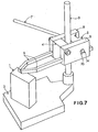
- the rings 4-5 arranged on either side of the column 3 are formed from two blocks substantially of parallelepiped shape.
- the ring 4 supports on its two sides lateral parts 8-9 serving as elements of. holding and positioning the pressure rod 6 consisting of two parallel arms.
- the blocking against the column 3 is achieved by means of the single control lever 7 which causes the rotation of a cam 34 fony the embodiment is shown in more detail in FIG. 9.
- the central part of the cam 34 causes the rear ring 5 to be tightened against the column 3, this being favored by the fact that the orifice 35 provided in the lateral parts 8-9 has a diameter greater than that of the end of said cam 34, this which also makes it possible to make the pressure arms relatively independent in the embodiment of FIG. 7.
- the pressure rod is formed by two removable parallel arms 6 which are mounted so that they can be moved independently of one another.
- the arms 6 are maintained by means of a plate 31 pivotally mounted, by means of an axis 42, on the front face of the ring 4.
- a flexible blade 40 disposed below the arms 6 ensures the maintenance in the notches provided at the ends of the plate 41.
- the ring 4 is substantially in the form of a U, the rear ring 5 being constituted simply by a plate embedded in two grooves provided on the parts side 8-9 of the front ring 4.
- this rear ring 5 may comprise a flexible blade 43 forming a spring, a blade against which the cam bears ensuring the tightening of the immobilization of the together against column 3.
- This embodiment is particularly advantageous not only for its great simplicity but also for the fact that it makes it possible to ensure the clamping of part 1 having a variable configuration, for example variations in its thickness.
- the lever 7 which, as previously causes the rotation of a cam assembly 34, it causes not only the tightening of the rear ring 5 against the column 3 but also, due to the pivoting mounting of each of the arm 6 on the front ring 4, holding the part 1, even when it has a variable thickness as illustrated.
- the invention Compared with prior blocking devices, the invention has very great advantages.
- the pressure rod can have a completely different configuration than those described, the active part of this tie being able to be adapted according to the shape of the parts to be worked. It could also be envisaged to reverse the position, relative to the column, of the locking means.
Landscapes
- Engineering & Computer Science (AREA)
- Mechanical Engineering (AREA)
- Jigs For Machine Tools (AREA)
Applications Claiming Priority (2)
| Application Number | Priority Date | Filing Date | Title |
|---|---|---|---|
| FR8016757A FR2487238A1 (fr) | 1980-07-25 | 1980-07-25 | Dispositif de blocage d'une piece lors d'une operation d'usinage, notamment de percage |
| FR8016757 | 1980-07-25 |
Publications (2)
| Publication Number | Publication Date |
|---|---|
| EP0045272A1 EP0045272A1 (fr) | 1982-02-03 |
| EP0045272B1 true EP0045272B1 (fr) | 1984-09-05 |
Family
ID=9244682
Family Applications (1)
| Application Number | Title | Priority Date | Filing Date |
|---|---|---|---|
| EP81420102A Expired EP0045272B1 (fr) | 1980-07-25 | 1981-07-08 | Dispositif de blocage d'une pièce lors d'une opération d'usinage notamment de perçage |
Country Status (4)
| Country | Link |
|---|---|
| US (1) | US4477063A (enExample) |
| EP (1) | EP0045272B1 (enExample) |
| DE (1) | DE3165852D1 (enExample) |
| FR (1) | FR2487238A1 (enExample) |
Families Citing this family (7)
| Publication number | Priority date | Publication date | Assignee | Title |
|---|---|---|---|---|
| DE3244689A1 (de) * | 1982-11-30 | 1984-05-30 | Siemens AG, 1000 Berlin und 8000 München | Vorrichtung zur lagegenauen positionierung der lwl-faserenden von lwl-bauteilen |
| GB8801190D0 (en) * | 1988-01-20 | 1988-02-17 | Rhombus Tools Ltd | Clamp |
| US4884792A (en) * | 1988-08-11 | 1989-12-05 | Lake Center Industries A Division Of Guy F. Atkinson Company | Clamp |
| DE9200970U1 (de) * | 1992-01-28 | 1992-03-26 | Sánchez Giraldez, José Humberto, 2112 Jesteburg | Spannvorrichtung |
| FR2690863B1 (fr) * | 1992-05-06 | 1994-10-28 | Jean Deligny | Dispositif de blocage d'une pièce à usiner. |
| NO335859B2 (no) * | 2013-12-10 | 2016-11-21 | Salthammer Tresfjord As | Anordning for sikker håndtering av ankerplater |
| CN106041568A (zh) * | 2016-08-04 | 2016-10-26 | 铜陵市永生机电制造有限责任公司 | 一种用于铣大头销的夹具 |
Family Cites Families (11)
| Publication number | Priority date | Publication date | Assignee | Title |
|---|---|---|---|---|
| US824000A (en) * | 1905-11-13 | 1906-06-19 | John K Elmer | Vise. |
| US2486638A (en) * | 1946-05-06 | 1949-11-01 | Virgil W Eshleman | Drill press clamp |
| US3345589A (en) * | 1962-12-14 | 1967-10-03 | Bell Telephone Labor Inc | Transmission line type microwave filter |
| US3382742A (en) * | 1964-10-15 | 1968-05-14 | Neil J. Gibbs | Drilling clamp |
| FR1441509A (fr) * | 1965-02-26 | 1966-06-10 | Materiel Telephonique | Presse-pièce pour machine-outil |
| US3345889A (en) * | 1965-05-18 | 1967-10-10 | Northrop Corp | Slide and grip quick-action cam-lock clamp |
| US3333487A (en) * | 1965-10-20 | 1967-08-01 | Parry John | Valve guide reboring device |
| GB1328195A (en) * | 1971-04-22 | 1973-08-30 | Turnerson Ltd | Workpiece clamping devices |
| US4025064A (en) * | 1976-02-09 | 1977-05-24 | Disston Jr Horace C | Work hold-down for a machine tool having a table and column |
| US4232856A (en) * | 1979-02-16 | 1980-11-11 | Eichfeld Timothy J | Work holding table |
| US4299146A (en) * | 1979-10-26 | 1981-11-10 | Phelps Richard E | Clamping device |
-
1980
- 1980-07-25 FR FR8016757A patent/FR2487238A1/fr active Granted
-
1981
- 1981-07-08 DE DE8181420102T patent/DE3165852D1/de not_active Expired
- 1981-07-08 EP EP81420102A patent/EP0045272B1/fr not_active Expired
- 1981-07-21 US US06/285,541 patent/US4477063A/en not_active Expired - Fee Related
Also Published As
| Publication number | Publication date |
|---|---|
| US4477063A (en) | 1984-10-16 |
| EP0045272A1 (fr) | 1982-02-03 |
| DE3165852D1 (en) | 1984-10-11 |
| FR2487238A1 (fr) | 1982-01-29 |
| FR2487238B1 (enExample) | 1984-02-24 |
Similar Documents
| Publication | Publication Date | Title |
|---|---|---|
| EP0210083B1 (fr) | Système de changement rapide de mors de serrage sur une machine-outil | |
| FR2827420A1 (fr) | Dispositif de fixation pour des detecteurs tels que des capteurs de proximite | |
| EP0045272B1 (fr) | Dispositif de blocage d'une pièce lors d'une opération d'usinage notamment de perçage | |
| FR2598946A1 (fr) | Dispositif de fixation d'un poincon ou d'une matrice sur un tablier d'une presse plieuse | |
| EP0384161B1 (fr) | Dispositif de fixation d'une forme d'usinage sur un cylindre porte-outil dans une machine rotative | |
| FR2610857A1 (fr) | Dispositif antivibration et dispositif de guidage pour scie a ruban | |
| WO2002020203A2 (fr) | Tete a aleser | |
| EP2546011A1 (fr) | Dispositif de maintien de pièces mécaniques | |
| EP0734338A1 (fr) | Fixation de l'une des roues d'un motocycle sur socle et banc d'essai a rouleau associe | |
| FR2896713A1 (fr) | Mandrin porte-outil pour l'equipement d'une machine tournante | |
| EP0437413B1 (fr) | Structure unitaire déplaçable de calage ou de soutien d'un véhicule routier par ses roues | |
| FR2531889A1 (fr) | Dispositif pour serrer une lame de scie dans une machine servant a faconner des scies | |
| FR2646151A1 (fr) | Bloc de serrage a machoires auto-serreuses, notamment pour treuil hydraulique lineaire | |
| WO2001003894A1 (fr) | Dispositif de positionnement d'une plaque sur un cylindre a fixation magnetique | |
| FR2778860A1 (fr) | Buse de guidage de fil, unite a buses et mecanisme de fixation d'une telle unite | |
| WO2012076767A2 (fr) | Bride de serrage-desserrage | |
| EP1445168A1 (fr) | Dispositif de blocage vertical d'une colonne de direction de véhicule automobile | |
| FR2807131A1 (fr) | Disposition d'assemblage de cames sur un arbre de commande commun | |
| FR2690367A1 (fr) | Dispositif de positionnement d'un outil ou d'une pièce sur une machine-outil. | |
| FR2540841A1 (fr) | Convoyeur a rouleaux de friction | |
| FR2796977A1 (fr) | Dispositif d'assistance a la pose de lambris | |
| FR2556268A1 (fr) | Dispositif de coupe rotative d'une nappe de materiau sur enclume | |
| EP0086165B1 (fr) | Dispositif pour le maintien, le positionnement et l'entraînement d'un support tubulaire lors de l'enroulement d'une matière en feuille | |
| FR2535238A1 (fr) | Pince-etau a grande capacite d'ecartement | |
| EP0126436A1 (fr) | Dispositif de positionnement d'un étau sur une embase de perceuse à colonne |
Legal Events
| Date | Code | Title | Description |
|---|---|---|---|
| PUAI | Public reference made under article 153(3) epc to a published international application that has entered the european phase |
Free format text: ORIGINAL CODE: 0009012 |
|
| AK | Designated contracting states |
Designated state(s): CH DE FR GB IT |
|
| 17P | Request for examination filed |
Effective date: 19820608 |
|
| ITF | It: translation for a ep patent filed | ||
| GRAA | (expected) grant |
Free format text: ORIGINAL CODE: 0009210 |
|
| AK | Designated contracting states |
Designated state(s): CH DE FR GB IT LI |
|
| REF | Corresponds to: |
Ref document number: 3165852 Country of ref document: DE Date of ref document: 19841011 |
|
| PLBE | No opposition filed within time limit |
Free format text: ORIGINAL CODE: 0009261 |
|
| STAA | Information on the status of an ep patent application or granted ep patent |
Free format text: STATUS: NO OPPOSITION FILED WITHIN TIME LIMIT |
|
| 26N | No opposition filed | ||
| PG25 | Lapsed in a contracting state [announced via postgrant information from national office to epo] |
Ref country code: LI Effective date: 19880731 Ref country code: CH Effective date: 19880731 |
|
| REG | Reference to a national code |
Ref country code: CH Ref legal event code: PL |
|
| PGFP | Annual fee paid to national office [announced via postgrant information from national office to epo] |
Ref country code: GB Payment date: 19910702 Year of fee payment: 11 |
|
| PGFP | Annual fee paid to national office [announced via postgrant information from national office to epo] |
Ref country code: DE Payment date: 19910722 Year of fee payment: 11 |
|
| PG25 | Lapsed in a contracting state [announced via postgrant information from national office to epo] |
Ref country code: GB Effective date: 19920708 |
|
| GBPC | Gb: european patent ceased through non-payment of renewal fee |
Effective date: 19920708 |
|
| PG25 | Lapsed in a contracting state [announced via postgrant information from national office to epo] |
Ref country code: DE Effective date: 19930401 |
|
| REG | Reference to a national code |
Ref country code: FR Ref legal event code: CL |
|
| REG | Reference to a national code |
Ref country code: FR Ref legal event code: CL |
|
| PGFP | Annual fee paid to national office [announced via postgrant information from national office to epo] |
Ref country code: FR Payment date: 19950728 Year of fee payment: 15 |
|
| PG25 | Lapsed in a contracting state [announced via postgrant information from national office to epo] |
Ref country code: FR Effective date: 19970328 |
|
| REG | Reference to a national code |
Ref country code: FR Ref legal event code: ST |