EP0045152B1 - Collapsible and erectable container - Google Patents
Collapsible and erectable container Download PDFInfo
- Publication number
- EP0045152B1 EP0045152B1 EP19810303213 EP81303213A EP0045152B1 EP 0045152 B1 EP0045152 B1 EP 0045152B1 EP 19810303213 EP19810303213 EP 19810303213 EP 81303213 A EP81303213 A EP 81303213A EP 0045152 B1 EP0045152 B1 EP 0045152B1
- Authority
- EP
- European Patent Office
- Prior art keywords
- panels
- panel
- strap
- base panel
- interconnected
- Prior art date
- Legal status (The legal status is an assumption and is not a legal conclusion. Google has not performed a legal analysis and makes no representation as to the accuracy of the status listed.)
- Expired
Links
Images

Classifications
-
- B—PERFORMING OPERATIONS; TRANSPORTING
- B65—CONVEYING; PACKING; STORING; HANDLING THIN OR FILAMENTARY MATERIAL
- B65D—CONTAINERS FOR STORAGE OR TRANSPORT OF ARTICLES OR MATERIALS, e.g. BAGS, BARRELS, BOTTLES, BOXES, CANS, CARTONS, CRATES, DRUMS, JARS, TANKS, HOPPERS, FORWARDING CONTAINERS; ACCESSORIES, CLOSURES, OR FITTINGS THEREFOR; PACKAGING ELEMENTS; PACKAGES
- B65D7/00—Containers having bodies formed by interconnecting or uniting two or more rigid, or substantially rigid, components made wholly or mainly of metal
- B65D7/12—Containers having bodies formed by interconnecting or uniting two or more rigid, or substantially rigid, components made wholly or mainly of metal characterised by wall construction or by connections between walls
- B65D7/24—Containers having bodies formed by interconnecting or uniting two or more rigid, or substantially rigid, components made wholly or mainly of metal characterised by wall construction or by connections between walls collapsible, e.g. with all parts detachable
- B65D7/26—Containers having bodies formed by interconnecting or uniting two or more rigid, or substantially rigid, components made wholly or mainly of metal characterised by wall construction or by connections between walls collapsible, e.g. with all parts detachable with all parts hinged together
-
- B—PERFORMING OPERATIONS; TRANSPORTING
- B65—CONVEYING; PACKING; STORING; HANDLING THIN OR FILAMENTARY MATERIAL
- B65D—CONTAINERS FOR STORAGE OR TRANSPORT OF ARTICLES OR MATERIALS, e.g. BAGS, BARRELS, BOTTLES, BOXES, CANS, CARTONS, CRATES, DRUMS, JARS, TANKS, HOPPERS, FORWARDING CONTAINERS; ACCESSORIES, CLOSURES, OR FITTINGS THEREFOR; PACKAGING ELEMENTS; PACKAGES
- B65D11/00—Containers having bodies formed by interconnecting or uniting two or more rigid, or substantially rigid, components made wholly or mainly of plastics material
- B65D11/18—Containers having bodies formed by interconnecting or uniting two or more rigid, or substantially rigid, components made wholly or mainly of plastics material collapsible, i.e. with walls hinged together or detachably connected
- B65D11/1833—Containers having bodies formed by interconnecting or uniting two or more rigid, or substantially rigid, components made wholly or mainly of plastics material collapsible, i.e. with walls hinged together or detachably connected whereby all side walls are hingedly connected to the base panel
-
- B—PERFORMING OPERATIONS; TRANSPORTING
- B65—CONVEYING; PACKING; STORING; HANDLING THIN OR FILAMENTARY MATERIAL
- B65D—CONTAINERS FOR STORAGE OR TRANSPORT OF ARTICLES OR MATERIALS, e.g. BAGS, BARRELS, BOTTLES, BOXES, CANS, CARTONS, CRATES, DRUMS, JARS, TANKS, HOPPERS, FORWARDING CONTAINERS; ACCESSORIES, CLOSURES, OR FITTINGS THEREFOR; PACKAGING ELEMENTS; PACKAGES
- B65D9/00—Containers having bodies formed by interconnecting or uniting two or more rigid, or substantially rigid, components made wholly or mainly of wood or substitutes therefor
- B65D9/12—Containers having bodies formed by interconnecting or uniting two or more rigid, or substantially rigid, components made wholly or mainly of wood or substitutes therefor collapsible, e.g. with all parts detachable
- B65D9/14—Containers having bodies formed by interconnecting or uniting two or more rigid, or substantially rigid, components made wholly or mainly of wood or substitutes therefor collapsible, e.g. with all parts detachable with all parts hinged together
Definitions
- the invention concerns improvements in or relating to collapsible and erectable containers.
- the present invention seeks to overcome certain difficulties experienced in banding erected containers of box form, especially when such containers are destined to carry goods for which a tightly sealed lid panel is unnecessary.
- the bands simply run around the outer surface of the container. When there is no lid they extend across the open top surface of the container. This can be very inconvenient should the goods within the container have an irregular shape or project out of the container. Also, it is inconvenient for the bands running across the top of a lidless box or case because they may be caught and broken during handling, transportation and storage.
- the present invention seeks to remedy these drawbacks and provides a collapsible and errectable container (a term intended to be sufficiently compendious to include boxes, cases, crates, trays and the like) comprising a base panel and a pair of opposite side panels and a pair of opposite end panels, characterised in that a flexible strap is provided which interconnects either the panels of the pair of side panels or the panels of the pair of end panels, the strap being of such a length that when the two interconnected panels are laid flat with the strap taut, the panels are spaced apart by a dimension corresponding generally to the width of the base panel (if the interconnected panels are side panels) or the length of the base panel (if the interconnected panels are end panels), the said dimension being such that the base panel can be located on top of the strap spanning the interconnected panels when the latter are flat and such that the interconnected panels when swung upwardly about opposite edges of the base panel cause the strap to be tensioned and thereby to hold the interconnected panels in tight engagement with the base panel
- the distance between interconnected side panels or between interconnected end panels when laid flat with the strap taut need not be exactly the same as the width or the length of the base panel although it will always be approximately the same as the said width or length. What is important is that the distance between the side or end panels must be such that, when they are swung upwards about the base panel, the interconnecting strap is tensioned. Factors that lead to a deviation of the said distance between interconnected side (or end) panels from the exact width or length of the base panel include the elasticity of the strap and the width of the side (or end) panels and of the base panel.
- the distance between the interconnected panels can be less than if a less elastic strap is used since the elastic strap can be stretched a little to make up for the shorter distance between the panels. Also, if very thick panels are used, itwill readily be appreciated that the distance between interconnected panels will have to be greater to pass around the edges of the panels than if the panels were thinner.
- each flexible strap and the configuration of the complementary co-operating edges of contiguous panels are such that on assembly of the container there is a small gap between the said edges through which each strap extends between the outside and the inside of the container.
- the gaps for the straps may be provided by suitably forming e.g. by notching the panels themselves, or by providing slots in the straps themselves.
- the entire interior of the container remains fully accessible to goods and yet the container is securely banded together.
- a loose (floating) lid may then also be secured to the container and readily removed therefrom without dismantling the whole container.
- the straps may be of any suitable flexible material capable of withstanding repeated bending in either angular sense.
- the mode of securing the ends of the straps to the panels may also be varied considerably; thus they may be stapled or adhesively bonded (indeed the straps may be of commercially available adhesive tape or band) or they may be formed as plugs to fit tightly into corresponding recesses formed in the surfaces of the panels.
- the strap may be in the form of an endless loop passing around the interconnected panels so as to completely or partially encircle the latter; it may partially encircle a panel by passing through an aperture in the panel.
- a slit may run from an edge of each panel, conveniently the edge in engagement with the base panel, into the aperture to enable the endless loop to be inserted into the aperture.
- the base panel may be completely detachable from the flexible strap, in which case during erection, the base panel is placed on the top of the portion of the strap spanning the panels, or the strap may be permanently attached to the underside of the base panel.
- the adjacent edges of the base panel and/or the side panels and/or the end panels are provided with formations which act to guide upward pivotal movement of the side or end panels with respect to the base panel.
- formations may take the form of the complementary recesses and projections which not only interengage during upward pivotal movement of the side or end panels to assist in defining the pivot axes about which the panels swing, but also interengage in the erected container to assist rigidity.
- the formations are provided by rebates or recesses defined by the attachment to the interior side of each side and/or end panel, of a strip or strips set back from the edge of the respective side or end panel adjacent the base panel.
- Opposite edges of the base panel locate in the recesses or rebates, and this location is very effective in defining the pivot axes about which the side or end panels are to be swung and resisting any tendency for the base panel to be squeezed upwardly by the upwardly pivoting side or end panels.
- the interconnected panels are often joined by a plurality of spaced straps.
- the straps are conveniently made of a heat-sealable, flat plastics tape which is substantially non-extensible, extremely strong and readily joined by heat sealing to form the optional endless loop.
- the side panels are interconnected by a strap or straps and also the end panels are interconected by a strap or straps (in the manner described above) so that in the erection of the container, the base panel is placed between the two side panels and between the two end panels (if the base panel is not already so located), the side panels and end panels being swung upwardly into vertical positions and held in these vertical positions, for example by an encircling band or strap, possibly aided by the interengagement of projections and recesses on the adjoining edges of the side and end panels.
- the resulting container is extremely strong and rigid, is easily collapsible and readily transportable in a collapsed, compact condition with its component panels flat.
- the side and end panels may be swung upwardly to enclose contents previously placed on the base panel, enabling packing of the contents and erection of the container to proceed in a single swift operation.
- a collapsible and erectable container according to the invention may have a band of flexible material for encircling or substantially encircling the erected side and end panels and tightening means which are capable of being manually manipulated to tighten the band around the side and end panels by means of a progressive wedging action applied to the band, and to release the tightened band.
- the band may be an endless loop for completely encircling the side and end panels.
- the tightening means preferably comprise a wedge with a width across its wedging faces, in relation to the dimension of the band, enabling the wedge to be pushed between the band and one end or side panel with a progressive wedging action which steadily tensions the band.
- Said one end or side panel may have an opening to enable a portion of the band to be passed therethrough into the interior of the container, the wedge being inserted through this portion of the band and against the interior surface of said one end or side panel.
- the opening may be a slot having a horizontal width substantially equal to the thickness of the wedge plus twice the thickness of the material of the band, so that the band passes smoothly across the junction between the slot wall and the wedge without there being any pinching of the band between the wedge and said one panel (which would impede tightening of the band) and without there being undue clearance between the side faces of the wedges and the portions of the band passing thereacross (which would cause less effective retention of the wedge by the band).
- the wedge is conveniently made from the same sheet material as the panels of the container, and the band is conveniently made from the flat plastics tape already mentioned.
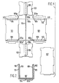
- the illustrated container has two side panels 101 which are identical and are generally rectangular but formed with projections and recesses around their peripheries as shown.
- the two side panels 101 are interconnected by two loops 102 of flexible, almost non-extensible, flat plastics tape the ends of which are heat sealed to form the continuous loops 102 which encircle both side panels. That is to say, each loop 102 passes over the surface of each side panel 101, the portion 102a of each loop 102 shown spanning the side panels 101 being the upper layer of two superimposed layers of the loop 102.
- the container also has two identical end panels 103 which are substantially square but formed with projections and - recesses around their peripheries as shown.
- the two end panels 103 are interconnected by a further endless loop 104 of the plastics tape, this further loop 104 being similar to but longer than each of the loops 102.
- each side panel 101 On one side of each side panel 101 (the side visible in Figure 1) are attached two strips 105 of card or board, each loop 102 passing between the corresponding strip 105 and the side panel 101 in order to locate the loop 102 which, however, can be pulled lengthwise between the strips 105 and the side panel 101.
- a similar strip 106 is attached to each end panel 103.
- the loops 102 and 104 are of a length such that when the side and end panels 101, 103 are laid flat with the loops 102 and 104 taut (as shown in Figure 1) the side panels 101 and the end panels 103 are spaced apart to an extent enabling the base panel 107 (shown in the lower right-hand part of Figure 1) to be fitted between the side and end panels 101 and 103.
- the base panel 107 is also rectangular in general shape but is formed with projections and recesses which fit the recesses and projections respectively along the adjacent edges of the side and end panels 101 and 103.
- the two end panels 103 are laid flat with the loop 104 taut and the two side panels 101 are laid flat with the loops 102 taut and across the loop 104.
- the base panel 107 is then placed on top of the loops 102 and 104.
- the two side panels 101 and the two end panels 103 are then swung upwardly around their lower edges, the edges of the projections on the base panel 107 optionally being chamfered to facilitate this movement.
- the projections and recesses on the panels 101, 103 and 107 come into abutting engagement and therefore guide the pivotal movement of each side and end panel 101, 103 by defining the axis of pivotal movement.
- the edges 105a, 106a of the strips 105, 106 assist in this guidance because they are set back from the outer edges of the projections by a dimension corresponding to the thickness of the base panel 107.
- Figure 2 shows a sectional view, taken on the location VII-VII in Figure 1, but after the side panels 101 and end panels 103 have been swung upwardly to their vertical positions so as to form an open-topped container.
- Figure 2 illustrates the loops 102 as being slack so that they show: it will be appreciated that the loops 102 are in fact tensioned and act to hold the side panels 101 in firm engagement with the base panel.
- the projections and recesses on the side and end panels interengage and these panels may be held in position by stapling, adhesive or by an encircling band.
- a lid may be provided if desired.
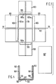
- Each side panel 101 is a rectangular board without projections or recesses.
- the edge 105a of each strip being set back from the adjacent edge of the side panel 101 by a dimension equal to the thickness of the base panel 107 which is plain rectangular board.
- An endless loop 102 of the plastics tape encircles both panels 101, passing between each strip 105 and the corresponding panel 101.
- the two end panels 103 are provided with respective strips 106 and are interconnected by an endless loop 104 of the plastics tape, the loop 104 passing between each strip 106 and the corresponding panel 103.
- the edge 106a of each strip is again set back from the adjacent edge of the end panel 103 by the thickness of the base panel 107.
- Figure 4 (which is a sectional view taken at location IX-IX in Figure 3) shows the panels 101 after they have been swung to their vertical positions in which they are held in tight engagement with the base panel 107 by the taut loops which are again shown slack so that they appear in the drawing.
- each strip 105 and 106 may be replaced by a plurality of shorter strips or by a strip of the form shown at 105 or 106 in Figure 1.
- Figure 5 shows the panels of the third embodiment of container.
- the container again has two side panels 101, two end panels 103 and a base panel 107, but in this embodiment the base panel 107 is permanently connected to the panels 101 and 103 instead of being separable therefrom, as in the containers of Figures 1 and 3.
- Figure 5 shows an underside plan view of the panels 101, 103 and 107, i.e. shows the sides of the panels 101, 103 and 107 which would be laid upon a flat surface during erection of the container.
- the endless loops 102 and 104 do not completely encircle the side panels 101 and end panels 103, respectively.
- each side panel 101 is formed with three spaced slits 108 through which the loops 102 pass.
- each end panel 103 is formed with two slits 109 through which the loops 104 pass.
- the panels 101 and 103 are further cut or slit from their adjacent edges, each of these further cuts or slits running from the adjacent panel edge to the slit 108 or 109.
- loops 102 and 104 pass across the underside of the base panel 107, they are retained by three elongate strips 110 of card or board the longer edges of which stapled or otherwise secured to the underside of the panel 107, to hold the base panel 107 captive with respect to the loops 102 and 104 but enabling the loops 102 and 104 to be slid longitudinally between the strips 110 and the base panel 107.
- This helps to avoid the loops 102 and 104 becoming snagged and provides a means of locating one erected container upon another when the containers are stacked.
- This location for stacking is achieved by attaching strips 112 to the upper surface of the lid panel 113 in a configuration such that the strips 112 on the upper surface of the lid panel 113 nest within spaces left between the strips 110 on the underside of the base panel 107.
- the edges of the panels 101, 103 and 113 are formed with the projections and recesses shown, these interengaging in the erected container.
- the container of Figure 5 also includes a wedge 114 which is conveniently cut from the same sheet material as the panels 101, 103, 107 and 113.
- the wedge 114 is generally rectangular but has an angled edge 115 imparting the tapering profile shown.
- the wedge 114 is used to tighten an endless loop 116 ( Figure 6) of the plastics tape around the erected side panels and end panels 101 and 103 in order to hold these panels in their vertical positions, as illustrated by the fragmentary view of Figure 6.
- the endless loop 116 is passed around the erected panels 101 and 103 and a portion 117 of the loop 116 is inserted, through a slot 118 in one end panel 103, into the interior of the partially erected container.
- the wedge 114 is then pushed downwardly, with the smaller end of its tapering profile leading, into the loop portion 117, extending into the interior of the container.
- This progressive wedging action provides a very effective way of tightening the loop 116 manually, without the need for a banding machine.
- the wedge 114 may be left to project perpendicularly from the end panel 103, or may be swung to lie against the interior surface of the panel 103, this having the effect of applying a further slight tensioning to the loop 116.
- the wedge 114 may be secured against the end panel 103 by adhesive tape or a staple, or the contents of the container can be used to hold the wedge 114 against the interior surface of the end panel 103.
- the wedge 114 can be simply withdrawn to loosen the loop 116 and enable the container to be collapsed.
- the width of the slot 118 is substantially equal to the thickness of the wedge 114 plus twice the thickness of a single run of the loop 116, so that the latter can be drawn smoothly through the slot 118 during wedging and so that the wedge 114 is adequately supported on its side faces by the loop portion 117 passing thereacross.
- the height of the slot 118 is considerably less than the height of the wedge 114, the latter being urged against the interior surface of the end panel 103 both above and below the slot 118 when the loop 116 is tightened.
- a strip similar to the strip 105 of Figure 3 is attached to the opposite surface of each panel 101 from that visible in Figure 5, and a strip similar to the strip 106 of Figure 3 is attached to the opposite surface of each panel 103 from that visible in Figure 5.
- Figures 1 to 6 can be repeatedly erected and collapsed without weakening of the hinges formed by the loops 102 and 104, can be collapsed to a flat, compact condition for transport or storage and can if desired by erected with the intended contents supported on the base panel 107.
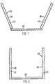
- Figures 7 and 8 are diagrammatic sectional views of a container having opposite side panels 101 and a base panel 107 interconnected by a broad loop or strap 120 formed from paper, plastics or other flexible material.
- the two thicknesses of the material of the loop 120 are preferably secured together over the length of the strap which passes under the base panel 107, in which case, the panels 101 are located in pockets 122 formed in the portions of the loop not secured together.
- the loop or strap 120 may have a substantial dimension in the direction perpendicular to the plane of Figures 7 and 8, and the term strap is to be construed broadly as including such a configuration.
- the internal surfaces of the pockets 122 may be coated with adhesive, e.g.
- FIG. 7 shows the side panels 101, in their pre-shaped pockets 122, being swung towards their vertical positions illustrated in Figure 8. End panels (not shown) of the container are interconnected by a strap similar to strap 120.
- the box shown in Figs. 7 and 8 works on the same principle as that shown in Fig. 1, the main difference between the two however, is that a single broad loop has been used in the box shown in Figs. 7 and 8 in the place of the two loops 102 shown in Fig. 1 and a further broad loop has been used in the box shown in Figs. 7 and 8 in place of the single loop 124 shown in Fig. 1.
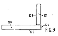
- Figure 9 shows a shaped metal strip 124 which can be used to assist assembly and final rigidity of a side panel 101 and base 107 of a container.
- the strip 124 has a vertical limb 125 forming an abutment for the vertical side panel 101 and a horizontal limb 126 forming the base of a recess accommodating the edge of the base panel 107.
- the horizontal ledge of the strip 124 adjoining the limb 125 serves to locate the lower edge of the panel 101. Since a plurality of such strips 124 (laced between the straps) locates the panels 101, 103 and 107, the panel edges need not be provided with recesses or projections nor provided with the strips such as shown at 105 and 106 in Figure 3. However, the straps, for example, loops 102 and 104 shown in Fig. 1, must still be provided when using a metal strip 124, which strip serves merely to assist in assembly and to improve rigidity.
Description
- The invention concerns improvements in or relating to collapsible and erectable containers.
- The present invention seeks to overcome certain difficulties experienced in banding erected containers of box form, especially when such containers are destined to carry goods for which a tightly sealed lid panel is unnecessary.
- In conventional banding procedure, the bands simply run around the outer surface of the container. When there is no lid they extend across the open top surface of the container. This can be very inconvenient should the goods within the container have an irregular shape or project out of the container. Also, it is inconvenient for the bands running across the top of a lidless box or case because they may be caught and broken during handling, transportation and storage.
- Accordingly, the present invention seeks to remedy these drawbacks and provides a collapsible and errectable container (a term intended to be sufficiently compendious to include boxes, cases, crates, trays and the like) comprising a base panel and a pair of opposite side panels and a pair of opposite end panels, characterised in that a flexible strap is provided which interconnects either the panels of the pair of side panels or the panels of the pair of end panels, the strap being of such a length that when the two interconnected panels are laid flat with the strap taut, the panels are spaced apart by a dimension corresponding generally to the width of the base panel (if the interconnected panels are side panels) or the length of the base panel (if the interconnected panels are end panels), the said dimension being such that the base panel can be located on top of the strap spanning the interconnected panels when the latter are flat and such that the interconnected panels when swung upwardly about opposite edges of the base panel cause the strap to be tensioned and thereby to hold the interconnected panels in tight engagement with the base panel.
- It will be appreciated that the distance between interconnected side panels or between interconnected end panels when laid flat with the strap taut need not be exactly the same as the width or the length of the base panel although it will always be approximately the same as the said width or length. What is important is that the distance between the side or end panels must be such that, when they are swung upwards about the base panel, the interconnecting strap is tensioned. Factors that lead to a deviation of the said distance between interconnected side (or end) panels from the exact width or length of the base panel include the elasticity of the strap and the width of the side (or end) panels and of the base panel. If a strap with a degree of elasticity is used, the distance between the interconnected panels can be less than if a less elastic strap is used since the elastic strap can be stretched a little to make up for the shorter distance between the panels. Also, if very thick panels are used, itwill readily be appreciated that the distance between interconnected panels will have to be greater to pass around the edges of the panels than if the panels were thinner.
- In one preferred embodiment, the length of each flexible strap and the configuration of the complementary co-operating edges of contiguous panels are such that on assembly of the container there is a small gap between the said edges through which each strap extends between the outside and the inside of the container. However, in an alternative preferred embodiment in which the panels are to abut tightly in the erected condition of the container, the gaps for the straps may be provided by suitably forming e.g. by notching the panels themselves, or by providing slots in the straps themselves.
- In the container of the present invention, the entire interior of the container remains fully accessible to goods and yet the container is securely banded together. A loose (floating) lid may then also be secured to the container and readily removed therefrom without dismantling the whole container.
- The straps may be of any suitable flexible material capable of withstanding repeated bending in either angular sense. The mode of securing the ends of the straps to the panels may also be varied considerably; thus they may be stapled or adhesively bonded (indeed the straps may be of commercially available adhesive tape or band) or they may be formed as plugs to fit tightly into corresponding recesses formed in the surfaces of the panels.
- The strap may be in the form of an endless loop passing around the interconnected panels so as to completely or partially encircle the latter; it may partially encircle a panel by passing through an aperture in the panel. In the latter case, a slit may run from an edge of each panel, conveniently the edge in engagement with the base panel, into the aperture to enable the endless loop to be inserted into the aperture. The base panel may be completely detachable from the flexible strap, in which case during erection, the base panel is placed on the top of the portion of the strap spanning the panels, or the strap may be permanently attached to the underside of the base panel.
- Preferably the adjacent edges of the base panel and/or the side panels and/or the end panels are provided with formations which act to guide upward pivotal movement of the side or end panels with respect to the base panel. These formations may take the form of the complementary recesses and projections which not only interengage during upward pivotal movement of the side or end panels to assist in defining the pivot axes about which the panels swing, but also interengage in the erected container to assist rigidity. Alternatively, or in addition, the formations are provided by rebates or recesses defined by the attachment to the interior side of each side and/or end panel, of a strip or strips set back from the edge of the respective side or end panel adjacent the base panel. Opposite edges of the base panel locate in the recesses or rebates, and this location is very effective in defining the pivot axes about which the side or end panels are to be swung and resisting any tendency for the base panel to be squeezed upwardly by the upwardly pivoting side or end panels.
- For most sizes of container, the interconnected panels are often joined by a plurality of spaced straps. The straps are conveniently made of a heat-sealable, flat plastics tape which is substantially non-extensible, extremely strong and readily joined by heat sealing to form the optional endless loop. Preferably, the side panels are interconnected by a strap or straps and also the end panels are interconected by a strap or straps (in the manner described above) so that in the erection of the container, the base panel is placed between the two side panels and between the two end panels (if the base panel is not already so located), the side panels and end panels being swung upwardly into vertical positions and held in these vertical positions, for example by an encircling band or strap, possibly aided by the interengagement of projections and recesses on the adjoining edges of the side and end panels. The resulting container is extremely strong and rigid, is easily collapsible and readily transportable in a collapsed, compact condition with its component panels flat. If desired, the side and end panels may be swung upwardly to enclose contents previously placed on the base panel, enabling packing of the contents and erection of the container to proceed in a single swift operation.
- A collapsible and erectable container according to the invention may have a band of flexible material for encircling or substantially encircling the erected side and end panels and tightening means which are capable of being manually manipulated to tighten the band around the side and end panels by means of a progressive wedging action applied to the band, and to release the tightened band. The band may be an endless loop for completely encircling the side and end panels.
- The tightening means preferably comprise a wedge with a width across its wedging faces, in relation to the dimension of the band, enabling the wedge to be pushed between the band and one end or side panel with a progressive wedging action which steadily tensions the band.
- Said one end or side panel may have an opening to enable a portion of the band to be passed therethrough into the interior of the container, the wedge being inserted through this portion of the band and against the interior surface of said one end or side panel. The opening may be a slot having a horizontal width substantially equal to the thickness of the wedge plus twice the thickness of the material of the band, so that the band passes smoothly across the junction between the slot wall and the wedge without there being any pinching of the band between the wedge and said one panel (which would impede tightening of the band) and without there being undue clearance between the side faces of the wedges and the portions of the band passing thereacross (which would cause less effective retention of the wedge by the band).
- The wedge is conveniently made from the same sheet material as the panels of the container, and the band is conveniently made from the flat plastics tape already mentioned.
- The invention will now be described purely by way of example, with reference to the accompanying drawings, wherein:
- Figure 1 is a plan view of a collapsed container forming a first embodiment of the invention;
- Figure 2 is a sectional view through the erected container of Figure 1;
- Figures 3 and 4 are views respectively corresponding to those of Figures 1 and 2 but of a container forming a second embodiment of the invention;
- Figure 5 is an underside plan view of the base, end and side panels of a collapsed container forming a third embodiment of the invention, together with a top plan view of a lid of the container and additionally showing a wedge of the container; and
- Figure 6 is a fragmentary perspective view showing the internal detail at one end of the erected container of Figure 5, and
- Figures 7 to 9 show possible detail modifications.
- Referring to Figures 1 and 2, the illustrated container has two
side panels 101 which are identical and are generally rectangular but formed with projections and recesses around their peripheries as shown. The twoside panels 101 are interconnected by twoloops 102 of flexible, almost non-extensible, flat plastics tape the ends of which are heat sealed to form thecontinuous loops 102 which encircle both side panels. That is to say, eachloop 102 passes over the surface of eachside panel 101, theportion 102a of eachloop 102 shown spanning theside panels 101 being the upper layer of two superimposed layers of theloop 102. The container also has twoidentical end panels 103 which are substantially square but formed with projections and - recesses around their peripheries as shown. The twoend panels 103 are interconnected by a furtherendless loop 104 of the plastics tape, thisfurther loop 104 being similar to but longer than each of theloops 102. - On one side of each side panel 101 (the side visible in Figure 1) are attached two
strips 105 of card or board, eachloop 102 passing between thecorresponding strip 105 and theside panel 101 in order to locate theloop 102 which, however, can be pulled lengthwise between thestrips 105 and theside panel 101. Asimilar strip 106 is attached to eachend panel 103. Theloops end panels loops side panels 101 and theend panels 103 are spaced apart to an extent enabling the base panel 107 (shown in the lower right-hand part of Figure 1) to be fitted between the side andend panels base panel 107 is also rectangular in general shape but is formed with projections and recesses which fit the recesses and projections respectively along the adjacent edges of the side andend panels - To erect the panels shown in Figure 1, the two
end panels 103 are laid flat with theloop 104 taut and the twoside panels 101 are laid flat with theloops 102 taut and across theloop 104. Thebase panel 107 is then placed on top of theloops side panels 101 and the twoend panels 103 are then swung upwardly around their lower edges, the edges of the projections on thebase panel 107 optionally being chamfered to facilitate this movement. During this pivoting movement the projections and recesses on thepanels end panel edges strips 105, 106 (i.e the edges closest to the base panel) assist in this guidance because they are set back from the outer edges of the projections by a dimension corresponding to the thickness of thebase panel 107. - Figure 2 shows a sectional view, taken on the location VII-VII in Figure 1, but after the
side panels 101 andend panels 103 have been swung upwardly to their vertical positions so as to form an open-topped container. Figure 2 illustrates theloops 102 as being slack so that they show: it will be appreciated that theloops 102 are in fact tensioned and act to hold theside panels 101 in firm engagement with the base panel. Along the four upright corners of the container, the projections and recesses on the side and end panels interengage and these panels may be held in position by stapling, adhesive or by an encircling band. A lid may be provided if desired. - The embodiment of container illustrated by the panels shown in Figures 3 and 4 is similar to that of Figures 1 and 2 and similar parts have been given the same reference numerals. Each
side panel 101 is a rectangular board without projections or recesses. On the side of eachside panel 101 visible in Figure 3 there is attached anelongated strip 105 of board or card. Theedge 105a of each strip being set back from the adjacent edge of theside panel 101 by a dimension equal to the thickness of thebase panel 107 which is plain rectangular board. Anendless loop 102 of the plastics tape encircles bothpanels 101, passing between eachstrip 105 and thecorresponding panel 101. In a similar fashion, the twoend panels 103 are provided withrespective strips 106 and are interconnected by anendless loop 104 of the plastics tape, theloop 104 passing between eachstrip 106 and thecorresponding panel 103. Theedge 106a of each strip is again set back from the adjacent edge of theend panel 103 by the thickness of thebase panel 107. - Assembly of the container shown in Figures 3 and 4 follows the sequence described for Figures 1 and 2; the
panels loops base panel 107 is placed centrally between thepanels panels base panel 107 locate within the rebates or recesses afforded by the setting back of theedges base panel 107 from being pushed upwardly by the convergingside panels 101 and endpanels 103. - Figure 4 (which is a sectional view taken at location IX-IX in Figure 3) shows the
panels 101 after they have been swung to their vertical positions in which they are held in tight engagement with thebase panel 107 by the taut loops which are again shown slack so that they appear in the drawing. - It will be appreciated that each
strip - Figure 5 shows the panels of the third embodiment of container. The container again has two
side panels 101, twoend panels 103 and abase panel 107, but in this embodiment thebase panel 107 is permanently connected to thepanels panels panels endless loops side panels 101 and endpanels 103, respectively. Instead, eachside panel 101 is formed with three spacedslits 108 through which theloops 102 pass. Similarly, eachend panel 103 is formed with twoslits 109 through which theloops 104 pass. To enable the preformed,endless loops slits panels slit - Where the
loops base panel 107, they are retained by threeelongate strips 110 of card or board the longer edges of which stapled or otherwise secured to the underside of thepanel 107, to hold thebase panel 107 captive with respect to theloops loops strips 110 and thebase panel 107. This helps to avoid theloops strips 112 to the upper surface of thelid panel 113 in a configuration such that thestrips 112 on the upper surface of thelid panel 113 nest within spaces left between thestrips 110 on the underside of thebase panel 107. The edges of thepanels - The container of Figure 5 also includes a
wedge 114 which is conveniently cut from the same sheet material as thepanels wedge 114 is generally rectangular but has anangled edge 115 imparting the tapering profile shown. Thewedge 114 is used to tighten an endless loop 116 (Figure 6) of the plastics tape around the erected side panels and endpanels panels base panel 107, in the manner previously described in connection with Figures 3 and 4, theendless loop 116 is passed around the erectedpanels portion 117 of theloop 116 is inserted, through aslot 118 in oneend panel 103, into the interior of the partially erected container. Thewedge 114 is then pushed downwardly, with the smaller end of its tapering profile leading, into theloop portion 117, extending into the interior of the container. As thewedge 114 is pushed downwardly, it draws more of theloop 116 through theslot 118 and thereby progressively tightens theloop 116 around thepanels loop 116 manually, without the need for a banding machine. - The
wedge 114 may be left to project perpendicularly from theend panel 103, or may be swung to lie against the interior surface of thepanel 103, this having the effect of applying a further slight tensioning to theloop 116. Thewedge 114 may be secured against theend panel 103 by adhesive tape or a staple, or the contents of the container can be used to hold thewedge 114 against the interior surface of theend panel 103. Thewedge 114 can be simply withdrawn to loosen theloop 116 and enable the container to be collapsed. - The width of the
slot 118 is substantially equal to the thickness of thewedge 114 plus twice the thickness of a single run of theloop 116, so that the latter can be drawn smoothly through theslot 118 during wedging and so that thewedge 114 is adequately supported on its side faces by theloop portion 117 passing thereacross. The height of theslot 118 is considerably less than the height of thewedge 114, the latter being urged against the interior surface of theend panel 103 both above and below theslot 118 when theloop 116 is tightened. A strip similar to thestrip 105 of Figure 3 is attached to the opposite surface of eachpanel 101 from that visible in Figure 5, and a strip similar to thestrip 106 of Figure 3 is attached to the opposite surface of eachpanel 103 from that visible in Figure 5. - The described embodiments of Figures 1 to 6 can be repeatedly erected and collapsed without weakening of the hinges formed by the
loops base panel 107. - Figures 7 and 8 are diagrammatic sectional views of a container having
opposite side panels 101 and abase panel 107 interconnected by a broad loop orstrap 120 formed from paper, plastics or other flexible material. The two thicknesses of the material of theloop 120 are preferably secured together over the length of the strap which passes under thebase panel 107, in which case, thepanels 101 are located inpockets 122 formed in the portions of the loop not secured together. The loop orstrap 120 may have a substantial dimension in the direction perpendicular to the plane of Figures 7 and 8, and the term strap is to be construed broadly as including such a configuration. The internal surfaces of thepockets 122 may be coated with adhesive, e.g. a watersoluble adhesive enabling wettedside panels 101 to be inserted into thepockets 122 and retained therein by the adhesive. The external surfaces of the straps may be printed with advertising material, instructions for use of the contents of the container or any other information. Figure 7 shows theside panels 101, in theirpre-shaped pockets 122, being swung towards their vertical positions illustrated in Figure 8. End panels (not shown) of the container are interconnected by a strap similar tostrap 120. Thus, the box shown in Figs. 7 and 8 works on the same principle as that shown in Fig. 1, the main difference between the two however, is that a single broad loop has been used in the box shown in Figs. 7 and 8 in the place of the twoloops 102 shown in Fig. 1 and a further broad loop has been used in the box shown in Figs. 7 and 8 in place of thesingle loop 124 shown in Fig. 1. - Figure 9 shows a shaped
metal strip 124 which can be used to assist assembly and final rigidity of aside panel 101 andbase 107 of a container. Thestrip 124 has avertical limb 125 forming an abutment for thevertical side panel 101 and ahorizontal limb 126 forming the base of a recess accommodating the edge of thebase panel 107. The horizontal ledge of thestrip 124 adjoining thelimb 125 serves to locate the lower edge of thepanel 101. Since a plurality of such strips 124 (laced between the straps) locates thepanels loops metal strip 124, which strip serves merely to assist in assembly and to improve rigidity.
Claims (12)
Priority Applications (1)
| Application Number | Priority Date | Filing Date | Title |
|---|---|---|---|
| AT81303213T ATE13034T1 (en) | 1980-07-25 | 1981-07-13 | COLLAPSIBLE AND RAISABLE CONTAINER. |
Applications Claiming Priority (4)
| Application Number | Priority Date | Filing Date | Title |
|---|---|---|---|
| GB8024470 | 1980-07-25 | ||
| GB8024470 | 1980-07-25 | ||
| GB8033791 | 1980-10-20 | ||
| GB8033791 | 1980-10-20 |
Publications (2)
| Publication Number | Publication Date |
|---|---|
| EP0045152A1 EP0045152A1 (en) | 1982-02-03 |
| EP0045152B1 true EP0045152B1 (en) | 1985-05-02 |
Family
ID=26276340
Family Applications (1)
| Application Number | Title | Priority Date | Filing Date |
|---|---|---|---|
| EP19810303213 Expired EP0045152B1 (en) | 1980-07-25 | 1981-07-13 | Collapsible and erectable container |
Country Status (4)
| Country | Link |
|---|---|
| EP (1) | EP0045152B1 (en) |
| DE (1) | DE3170273D1 (en) |
| DK (1) | DK332781A (en) |
| GR (1) | GR74294B (en) |
Families Citing this family (4)
| Publication number | Priority date | Publication date | Assignee | Title |
|---|---|---|---|---|
| DE9214567U1 (en) * | 1992-10-28 | 1994-03-03 | Mauser Werke Gmbh | Reusable transport container |
| DE9311769U1 (en) * | 1993-08-06 | 1993-12-16 | Mauser Werke Gmbh | Shipping container |
| US5454536A (en) * | 1994-01-13 | 1995-10-03 | Westinghouse Electric Corporation | Chair base assembly |
| GB2323588A (en) * | 1997-03-22 | 1998-09-30 | Impaq Limited | Collapsible structure with interlocking faces and securing means |
Family Cites Families (2)
| Publication number | Priority date | Publication date | Assignee | Title |
|---|---|---|---|---|
| AT29746B (en) * | 1905-08-02 | 1907-09-10 | Jakob Debeljak | Collapsible containers. |
| AT165425B (en) * | 1948-09-11 | 1950-02-25 | Cross-band joint for folding boxes and crates |
-
1981
- 1981-07-13 DE DE8181303213T patent/DE3170273D1/en not_active Expired
- 1981-07-13 EP EP19810303213 patent/EP0045152B1/en not_active Expired
- 1981-07-24 DK DK332781A patent/DK332781A/en not_active Application Discontinuation
- 1981-07-24 GR GR65620A patent/GR74294B/el unknown
Also Published As
| Publication number | Publication date |
|---|---|
| DK332781A (en) | 1982-01-26 |
| GR74294B (en) | 1984-06-21 |
| DE3170273D1 (en) | 1985-06-05 |
| EP0045152A1 (en) | 1982-02-03 |
Similar Documents
| Publication | Publication Date | Title |
|---|---|---|
| US4089417A (en) | Flap lock bulk bin | |
| US5016813A (en) | Fold-up container and construction method | |
| JPS62182035A (en) | Packaging case and packaging method | |
| PL166979B1 (en) | Holding case for a set of cans | |
| US4158410A (en) | Container blank including binding strap tabs | |
| CA1103599A (en) | Container | |
| US4715493A (en) | Composite package for a group of containers | |
| US4416376A (en) | Bag package and related method | |
| US3268147A (en) | Crates for the carriage and storage of various goods | |
| EP0045152B1 (en) | Collapsible and erectable container | |
| US5042684A (en) | Bag-less box for flowable materials | |
| US4033454A (en) | Method and structure for retaining shipping drums on pallets | |
| CA2577508A1 (en) | Laminate packaging | |
| FI120440B (en) | Packaging | |
| US3275216A (en) | Container | |
| EP0647565A1 (en) | Packaging for substantially rectangular blocks consisting of one or more articles | |
| JP2610152B2 (en) | Packing material for flat articles | |
| JP7444598B2 (en) | packaging box | |
| JP3462906B2 (en) | Fixtures such as tape | |
| JPS607309Y2 (en) | Cardboard box with partitions | |
| JPH0120276Y2 (en) | ||
| GB2264697A (en) | Containers | |
| JPS6236738Y2 (en) | ||
| SU1433864A1 (en) | Container of corrugated cardboard | |
| GB1284362A (en) | Improvements relating to bulk packs |
Legal Events
| Date | Code | Title | Description |
|---|---|---|---|
| PUAI | Public reference made under article 153(3) epc to a published international application that has entered the european phase |
Free format text: ORIGINAL CODE: 0009012 |
|
| 17P | Request for examination filed |
Effective date: 19810804 |
|
| AK | Designated contracting states |
Designated state(s): AT BE CH DE FR GB IT LU NL SE |
|
| GRAA | (expected) grant |
Free format text: ORIGINAL CODE: 0009210 |
|
| AK | Designated contracting states |
Designated state(s): AT BE CH DE FR GB IT LI LU NL SE |
|
| PG25 | Lapsed in a contracting state [announced via postgrant information from national office to epo] |
Ref country code: NL Effective date: 19850502 Ref country code: LI Effective date: 19850502 Ref country code: IT Free format text: LAPSE BECAUSE OF FAILURE TO SUBMIT A TRANSLATION OF THE DESCRIPTION OR TO PAY THE FEE WITHIN THE PRESCRIBED TIME-LIMIT;WARNING: LAPSES OF ITALIAN PATENTS WITH EFFECTIVE DATE BEFORE 2007 MAY HAVE OCCURRED AT ANY TIME BEFORE 2007. THE CORRECT EFFECTIVE DATE MAY BE DIFFERENT FROM THE ONE RECORDED. Effective date: 19850502 Ref country code: FR Free format text: THE PATENT HAS BEEN ANNULLED BY A DECISION OF A NATIONAL AUTHORITY Effective date: 19850502 Ref country code: CH Effective date: 19850502 Ref country code: BE Effective date: 19850502 Ref country code: AT Effective date: 19850502 |
|
| REF | Corresponds to: |
Ref document number: 13034 Country of ref document: AT Date of ref document: 19850515 Kind code of ref document: T |
|
| PG25 | Lapsed in a contracting state [announced via postgrant information from national office to epo] |
Ref country code: SE Effective date: 19850530 |
|
| REF | Corresponds to: |
Ref document number: 3170273 Country of ref document: DE Date of ref document: 19850605 |
|
| PG25 | Lapsed in a contracting state [announced via postgrant information from national office to epo] |
Ref country code: LU Free format text: LAPSE BECAUSE OF NON-PAYMENT OF DUE FEES Effective date: 19850731 |
|
| REG | Reference to a national code |
Ref country code: CH Ref legal event code: PL |
|
| NLV1 | Nl: lapsed or annulled due to failure to fulfill the requirements of art. 29p and 29m of the patents act | ||
| EN | Fr: translation not filed | ||
| PLBE | No opposition filed within time limit |
Free format text: ORIGINAL CODE: 0009261 |
|
| STAA | Information on the status of an ep patent application or granted ep patent |
Free format text: STATUS: NO OPPOSITION FILED WITHIN TIME LIMIT |
|
| PG25 | Lapsed in a contracting state [announced via postgrant information from national office to epo] |
Ref country code: DE Effective date: 19860402 |
|
| 26N | No opposition filed | ||
| GBPC | Gb: european patent ceased through non-payment of renewal fee | ||
| PG25 | Lapsed in a contracting state [announced via postgrant information from national office to epo] |
Ref country code: GB Effective date: 19881118 |