EP0045114A1 - Container for the storage of gas under low pressure, especially bio gas - Google Patents
Container for the storage of gas under low pressure, especially bio gas Download PDFInfo
- Publication number
- EP0045114A1 EP0045114A1 EP81200848A EP81200848A EP0045114A1 EP 0045114 A1 EP0045114 A1 EP 0045114A1 EP 81200848 A EP81200848 A EP 81200848A EP 81200848 A EP81200848 A EP 81200848A EP 0045114 A1 EP0045114 A1 EP 0045114A1
- Authority
- EP
- European Patent Office
- Prior art keywords
- gas
- wall
- tank according
- membrane
- pressure
- Prior art date
- Legal status (The legal status is an assumption and is not a legal conclusion. Google has not performed a legal analysis and makes no representation as to the accuracy of the status listed.)
- Granted
Links
- 239000012528 membrane Substances 0.000 claims abstract description 34
- 239000012530 fluid Substances 0.000 claims abstract description 5
- 239000007787 solid Substances 0.000 claims abstract description 5
- 239000007788 liquid Substances 0.000 claims abstract description 4
- XEEYBQQBJWHFJM-UHFFFAOYSA-N Iron Chemical compound [Fe] XEEYBQQBJWHFJM-UHFFFAOYSA-N 0.000 claims description 4
- 229910052742 iron Inorganic materials 0.000 claims description 2
- 239000011343 solid material Substances 0.000 claims description 2
- 239000000126 substance Substances 0.000 claims description 2
- 239000000463 material Substances 0.000 claims 1
- 210000003608 fece Anatomy 0.000 abstract description 12
- 239000010871 livestock manure Substances 0.000 abstract description 12
- XLYOFNOQVPJJNP-UHFFFAOYSA-N water Substances O XLYOFNOQVPJJNP-UHFFFAOYSA-N 0.000 abstract description 4
- 238000000855 fermentation Methods 0.000 abstract description 3
- 239000005416 organic matter Substances 0.000 abstract description 2
- 230000003247 decreasing effect Effects 0.000 abstract 1
- 229920005549 butyl rubber Polymers 0.000 description 2
- 235000016068 Berberis vulgaris Nutrition 0.000 description 1
- 241000335053 Beta vulgaris Species 0.000 description 1
- 244000025254 Cannabis sativa Species 0.000 description 1
- 241001465754 Metazoa Species 0.000 description 1
- 240000008042 Zea mays Species 0.000 description 1
- 235000016383 Zea mays subsp huehuetenangensis Nutrition 0.000 description 1
- 235000002017 Zea mays subsp mays Nutrition 0.000 description 1
- 238000009434 installation Methods 0.000 description 1
- 235000009973 maize Nutrition 0.000 description 1
- 238000007665 sagging Methods 0.000 description 1
- 238000000926 separation method Methods 0.000 description 1
- 239000002699 waste material Substances 0.000 description 1
Images

Classifications
-
- B—PERFORMING OPERATIONS; TRANSPORTING
- B65—CONVEYING; PACKING; STORING; HANDLING THIN OR FILAMENTARY MATERIAL
- B65D—CONTAINERS FOR STORAGE OR TRANSPORT OF ARTICLES OR MATERIALS, e.g. BAGS, BARRELS, BOTTLES, BOXES, CANS, CARTONS, CRATES, DRUMS, JARS, TANKS, HOPPERS, FORWARDING CONTAINERS; ACCESSORIES, CLOSURES, OR FITTINGS THEREFOR; PACKAGING ELEMENTS; PACKAGES
- B65D90/00—Component parts, details or accessories for large containers
- B65D90/22—Safety features
- B65D90/32—Arrangements for preventing, or minimising the effect of, excessive or insufficient pressure
-
- A—HUMAN NECESSITIES
- A01—AGRICULTURE; FORESTRY; ANIMAL HUSBANDRY; HUNTING; TRAPPING; FISHING
- A01C—PLANTING; SOWING; FERTILISING
- A01C3/00—Treating manure; Manuring
- A01C3/02—Storage places for manure, e.g. cisterns for liquid manure; Installations for fermenting manure
-
- B—PERFORMING OPERATIONS; TRANSPORTING
- B65—CONVEYING; PACKING; STORING; HANDLING THIN OR FILAMENTARY MATERIAL
- B65D—CONTAINERS FOR STORAGE OR TRANSPORT OF ARTICLES OR MATERIALS, e.g. BAGS, BARRELS, BOTTLES, BOXES, CANS, CARTONS, CRATES, DRUMS, JARS, TANKS, HOPPERS, FORWARDING CONTAINERS; ACCESSORIES, CLOSURES, OR FITTINGS THEREFOR; PACKAGING ELEMENTS; PACKAGES
- B65D88/00—Large containers
- B65D88/34—Large containers having floating covers, e.g. floating roofs or blankets
-
- B—PERFORMING OPERATIONS; TRANSPORTING
- B65—CONVEYING; PACKING; STORING; HANDLING THIN OR FILAMENTARY MATERIAL
- B65D—CONTAINERS FOR STORAGE OR TRANSPORT OF ARTICLES OR MATERIALS, e.g. BAGS, BARRELS, BOTTLES, BOXES, CANS, CARTONS, CRATES, DRUMS, JARS, TANKS, HOPPERS, FORWARDING CONTAINERS; ACCESSORIES, CLOSURES, OR FITTINGS THEREFOR; PACKAGING ELEMENTS; PACKAGES
- B65D90/00—Component parts, details or accessories for large containers
- B65D90/02—Wall construction
- B65D90/04—Linings
- B65D90/046—Flexible liners, e.g. loosely positioned in the container
-
- C—CHEMISTRY; METALLURGY
- C12—BIOCHEMISTRY; BEER; SPIRITS; WINE; VINEGAR; MICROBIOLOGY; ENZYMOLOGY; MUTATION OR GENETIC ENGINEERING
- C12M—APPARATUS FOR ENZYMOLOGY OR MICROBIOLOGY; APPARATUS FOR CULTURING MICROORGANISMS FOR PRODUCING BIOMASS, FOR GROWING CELLS OR FOR OBTAINING FERMENTATION OR METABOLIC PRODUCTS, i.e. BIOREACTORS OR FERMENTERS
- C12M21/00—Bioreactors or fermenters specially adapted for specific uses
- C12M21/04—Bioreactors or fermenters specially adapted for specific uses for producing gas, e.g. biogas
-
- C—CHEMISTRY; METALLURGY
- C12—BIOCHEMISTRY; BEER; SPIRITS; WINE; VINEGAR; MICROBIOLOGY; ENZYMOLOGY; MUTATION OR GENETIC ENGINEERING
- C12M—APPARATUS FOR ENZYMOLOGY OR MICROBIOLOGY; APPARATUS FOR CULTURING MICROORGANISMS FOR PRODUCING BIOMASS, FOR GROWING CELLS OR FOR OBTAINING FERMENTATION OR METABOLIC PRODUCTS, i.e. BIOREACTORS OR FERMENTERS
- C12M23/00—Constructional details, e.g. recesses, hinges
- C12M23/26—Constructional details, e.g. recesses, hinges flexible
-
- C—CHEMISTRY; METALLURGY
- C12—BIOCHEMISTRY; BEER; SPIRITS; WINE; VINEGAR; MICROBIOLOGY; ENZYMOLOGY; MUTATION OR GENETIC ENGINEERING
- C12M—APPARATUS FOR ENZYMOLOGY OR MICROBIOLOGY; APPARATUS FOR CULTURING MICROORGANISMS FOR PRODUCING BIOMASS, FOR GROWING CELLS OR FOR OBTAINING FERMENTATION OR METABOLIC PRODUCTS, i.e. BIOREACTORS OR FERMENTERS
- C12M23/00—Constructional details, e.g. recesses, hinges
- C12M23/36—Means for collection or storage of gas; Gas holders
-
- C—CHEMISTRY; METALLURGY
- C12—BIOCHEMISTRY; BEER; SPIRITS; WINE; VINEGAR; MICROBIOLOGY; ENZYMOLOGY; MUTATION OR GENETIC ENGINEERING
- C12M—APPARATUS FOR ENZYMOLOGY OR MICROBIOLOGY; APPARATUS FOR CULTURING MICROORGANISMS FOR PRODUCING BIOMASS, FOR GROWING CELLS OR FOR OBTAINING FERMENTATION OR METABOLIC PRODUCTS, i.e. BIOREACTORS OR FERMENTERS
- C12M23/00—Constructional details, e.g. recesses, hinges
- C12M23/38—Caps; Covers; Plugs; Pouring means
-
- C—CHEMISTRY; METALLURGY
- C12—BIOCHEMISTRY; BEER; SPIRITS; WINE; VINEGAR; MICROBIOLOGY; ENZYMOLOGY; MUTATION OR GENETIC ENGINEERING
- C12M—APPARATUS FOR ENZYMOLOGY OR MICROBIOLOGY; APPARATUS FOR CULTURING MICROORGANISMS FOR PRODUCING BIOMASS, FOR GROWING CELLS OR FOR OBTAINING FERMENTATION OR METABOLIC PRODUCTS, i.e. BIOREACTORS OR FERMENTERS
- C12M23/00—Constructional details, e.g. recesses, hinges
- C12M23/56—Floating elements
-
- C—CHEMISTRY; METALLURGY
- C12—BIOCHEMISTRY; BEER; SPIRITS; WINE; VINEGAR; MICROBIOLOGY; ENZYMOLOGY; MUTATION OR GENETIC ENGINEERING
- C12M—APPARATUS FOR ENZYMOLOGY OR MICROBIOLOGY; APPARATUS FOR CULTURING MICROORGANISMS FOR PRODUCING BIOMASS, FOR GROWING CELLS OR FOR OBTAINING FERMENTATION OR METABOLIC PRODUCTS, i.e. BIOREACTORS OR FERMENTERS
- C12M41/00—Means for regulation, monitoring, measurement or control, e.g. flow regulation
- C12M41/40—Means for regulation, monitoring, measurement or control, e.g. flow regulation of pressure
-
- Y—GENERAL TAGGING OF NEW TECHNOLOGICAL DEVELOPMENTS; GENERAL TAGGING OF CROSS-SECTIONAL TECHNOLOGIES SPANNING OVER SEVERAL SECTIONS OF THE IPC; TECHNICAL SUBJECTS COVERED BY FORMER USPC CROSS-REFERENCE ART COLLECTIONS [XRACs] AND DIGESTS
- Y02—TECHNOLOGIES OR APPLICATIONS FOR MITIGATION OR ADAPTATION AGAINST CLIMATE CHANGE
- Y02E—REDUCTION OF GREENHOUSE GAS [GHG] EMISSIONS, RELATED TO ENERGY GENERATION, TRANSMISSION OR DISTRIBUTION
- Y02E50/00—Technologies for the production of fuel of non-fossil origin
- Y02E50/30—Fuel from waste, e.g. synthetic alcohol or diesel
Definitions
- the invention relates to a tank for the storage of gas under low pressure, in particular biogas, which tank is provided with a vessel with at least a gas tight bottom and side wall of solid material, whereby on the inner side of the side wall, substantially near the upper end of the side wall, a movable gas tight inner wall is gas tight fixed, which inner wall comprises a thin, flexible membrane at least in the border part adjacent to the side wall, whereas in the thus formed gas tight gas space of variable volume into which at least one conduit debouches for the discharge of gas.
- a gas tank of this type is known from the British patent specification 1. 522.780 for the storage of biogas, which is kept under substantially constant pressure in the gas tank.
- biogas is produced on for instance farms or other agricultural installations, where greater amounts of waste masses are released, such as stable manure and liquid manure, which contain fermentable organic matter, from which biological gas can be produced by anaerobic fermentation.
- the object of the invention is providing a gas tank lacking the above indicated objections, which object is reached, in that above the inner wall a gas tight pressure space is formed, which is provided with means for the supply and/or removal of fluid, which means are connected to a pressure source, whereby the inner wall is maintained in a floating condition by the pressure difference between the above lying pressure space and the underlying gas space caused by the pressure source.
- the drawing shows a gas. tank which is provided with a round, cylindrical, vertical silo having a solid side wall 1 and a solid bottom 2, which are both preferably gas tight.
- a solid side wall 1 and a solid bottom 2 which are both preferably gas tight.
- On the side wall 1 an also gas tight, for instance conical roof 3 is mounted, which is supported by a number of roof joists 4.
- a silo is known per se and is at this time already applied on a large scale for the storage of fodder for animals, such as mown grass, hay, chopped maize and fodder beets, and so forth.
- a movable, gas tight inner wall 5 is fixedly mounted in a gas tight way.
- the inner wall 5 exists completely of a membrane 5 of soft and flexible, thin PVC having the form of a revolving body having a downwardly directed hollow that is symmetrically placed in the silo.
- a skirt 10 also of soft and flexible PVC is fastened below the membrane 5 and is hanging from the fastening of this membrane 5 to the side wall 1 along this side wall downwardly until near the bottom 2.
- the membrane 5 with the skirt 10 forms a gas tight lining for the gas space below the membrane.
- the membrane 5 is far downwardly bent in the starting position and contains for instance in the hollow an amount of ballast which is composed out of for instance stones or pieces of iron 6 and water 7.
- a conduit 11 which stretches until below the membrane 5.
- This conduit 11 is connected outside the silo 1, 2 to a blower 12 which is adapted for sucking gas out of the gas space.
- a valve 13 is placed in the conduit 11 before the blower 12.
- a conduit 14 which reaches inside the silo 1,2 until above the membrane 5 and is connected outside the silo 1, 2 to a blower 15 with which the pressure of the fluid F, such as for instance air, in the pressure space above the membrane 5 can be increased to chosen values.
- an amount 5 of manure M is placed, of which the upper surface is 8.
- biological gas G is produced by the anaerobic fermentation of the organic manure substances M.
- This manure M can also be placed in a separate generator (not shown) for biological gas G.
- the membrane 5 is gradually pressed upward, by which the membrane is displaced from the position according to figure 1, in which the lower side of the membrane is in contact with the upper side 8 of the manure M, to for instance a new balanced position according to figure 2, in which the membrane with or without contents floats above the manure surface 8 under influence of the pressur-e-difference and/or the weight loading.
- the membrane has preferably taken the shape of approximately a revolving paraboloid,but it can also have other forms, such as that of a halve sphere as long as on the one hand there remains enough hollow for containing the ballast which exerts a downward pressure on the membrane, as the proper weight of the membrane is relatively small, and this is not able to guarantee without pressure difference a sufficient pressure of the gas G in the gas space.
- the inner wall comprises a border membrane 5a, which is also fastened with its outer edge to the inner side of the vertical silo wall 1, and a central, rigid part 9.
- the rigid part 9 forms together with the border membrane 5a a hollow, in which again ballast, such as water 7 can be included, in order to load the inner wall 5a, 9 in a downward direction.
- the border membrane has been bent upwardly from the substantially oblique downward direction to an inverted V-shape.
- the means 11, 12 and 13 are present for the removal of biogas G from the gas space, as well as the fluid-pressure means 14 and 15.
- This embodiment is particularly suitable for narrow, high silos and for applications in which the unused space above the liquid or other ballast and the inner wall 5a, 9 must be kept as small as possible, so that the largest possible part of the silo can be used for manure and gas above it.
- the pressure difference over the inner wall and/or the amount of ballast can be altered in a simple way, by which the pressure of the gas G can be simply controlled, such as by adding water.
- the inner wall structure according to the invention an automatic centering of the ballast is reached and no separate guide elements are necessary in order to prevent the turning over and/or jamming of the inner wall against the side wall.
Landscapes
- Health & Medical Sciences (AREA)
- Life Sciences & Earth Sciences (AREA)
- Engineering & Computer Science (AREA)
- Chemical & Material Sciences (AREA)
- Wood Science & Technology (AREA)
- Organic Chemistry (AREA)
- Bioinformatics & Cheminformatics (AREA)
- Zoology (AREA)
- Genetics & Genomics (AREA)
- Biomedical Technology (AREA)
- Sustainable Development (AREA)
- Microbiology (AREA)
- Biotechnology (AREA)
- Biochemistry (AREA)
- General Engineering & Computer Science (AREA)
- General Health & Medical Sciences (AREA)
- Clinical Laboratory Science (AREA)
- Mechanical Engineering (AREA)
- Soil Sciences (AREA)
- Molecular Biology (AREA)
- Oil, Petroleum & Natural Gas (AREA)
- Analytical Chemistry (AREA)
- General Chemical & Material Sciences (AREA)
- Environmental Sciences (AREA)
- Filling Or Discharging Of Gas Storage Vessels (AREA)
- Purification Treatments By Anaerobic Or Anaerobic And Aerobic Bacteria Or Animals (AREA)
- External Artificial Organs (AREA)
Abstract
Description
- The invention relates to a tank for the storage of gas under low pressure, in particular biogas, which tank is provided with a vessel with at least a gas tight bottom and side wall of solid material, whereby on the inner side of the side wall, substantially near the upper end of the side wall, a movable gas tight inner wall is gas tight fixed, which inner wall comprises a thin, flexible membrane at least in the border part adjacent to the side wall, whereas in the thus formed gas tight gas space of variable volume into which at least one conduit debouches for the discharge of gas.
- A gas tank of this type is known from the
British patent specification 1. 522.780 for the storage of biogas, which is kept under substantially constant pressure in the gas tank. Such biogas is produced on for instance farms or other agricultural installations, where greater amounts of waste masses are released, such as stable manure and liquid manure, which contain fermentable organic matter, from which biological gas can be produced by anaerobic fermentation. - Hereby a membrane of flexible butyl rubber is applied, which is inflated into the outside atmosphere by the biological gas. Below the membrane a conical frame work support structure is fastened, which protects the membrane against sagging through at low gas pressure. Such gas cushion-gas tanks have the objection, that the butyl rubber is wholly or partly exposed'to sun light, by which this ages quickly and becomes lea-k, whereas these gas cushions are less suitable for greater dimensions, as they then become very sensitive for wind and have to be anchored in a reliable way.
- The object of the invention is providing a gas tank lacking the above indicated objections, which object is reached, in that above the inner wall a gas tight pressure space is formed, which is provided with means for the supply and/or removal of fluid, which means are connected to a pressure source, whereby the inner wall is maintained in a floating condition by the pressure difference between the above lying pressure space and the underlying gas space caused by the pressure source.
- In this gas tight pressure space according to the invention by the setting of the pressure source a fluid pressure of such a value is obtained, that the biogas can be stored in the gas space below the downwardly bent inner wall under substantially constant pressure.
- The invention will now be further elucidated referring to the accompanying drawing of some embodiments.
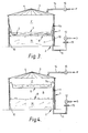
- Fig. 1 shows an axial cross section over a gas tank according to a first main embodiment of the invention in the starting condition.
- Fig. 2 shows a similar view as fig. 1 during the operation.
- Fig. 3 shows a similar view as fig. 1 of a second main embodiment of the invention.
- Fig. 4 shows a similar view as fig. 2 of the second main embodiment according to fig. 3.
- The drawing shows a gas. tank which is provided with a round, cylindrical, vertical silo having a
solid side wall 1 and asolid bottom 2, which are both preferably gas tight. On theside wall 1 an also gas tight, for instanceconical roof 3 is mounted, which is supported by a number ofroof joists 4. Such a silo is known per se and is at this time already applied on a large scale for the storage of fodder for animals, such as mown grass, hay, chopped maize and fodder beets, and so forth. - At the inside of the
side wall 1 of th- silo around the circumference thereof, for instance on the separation between theside wall 1 and theroof 3, a movable, gas tightinner wall 5 is fixedly mounted in a gas tight way. According to the first main embodiment of the invention shown in figs. 1 and 2, theinner wall 5 exists completely of amembrane 5 of soft and flexible, thin PVC having the form of a revolving body having a downwardly directed hollow that is symmetrically placed in the silo. Askirt 10 also of soft and flexible PVC is fastened below themembrane 5 and is hanging from the fastening of thismembrane 5 to theside wall 1 along this side wall downwardly until near thebottom 2. Thereby themembrane 5 with theskirt 10 forms a gas tight lining for the gas space below the membrane. Themembrane 5 is far downwardly bent in the starting position and contains for instance in the hollow an amount of ballast which is composed out of for instance stones or pieces ofiron 6 andwater 7. - Through the
side wall 1 or thebottom 2 extends aconduit 11 which stretches until below themembrane 5. Thisconduit 11 is connected outside thesilo blower 12 which is adapted for sucking gas out of the gas space. Avalve 13 is placed in theconduit 11 before theblower 12. Through theroof 3 extends aconduit 14 which reaches inside thesilo membrane 5 and is connected outside thesilo blower 15 with which the pressure of the fluid F, such as for instance air, in the pressure space above themembrane 5 can be increased to chosen values. In thesilo amount 5 of manure M is placed, of which the upper surface is 8. Between theupper surface 8 of the manure and the lower side of themembrane 5 biological gas G is produced by the anaerobic fermentation of the organic manure substances M. This manure M can also be placed in a separate generator (not shown) for biological gas G. As the pressure of this gas G in the gas space increases, themembrane 5 is gradually pressed upward, by which the membrane is displaced from the position according to figure 1, in which the lower side of the membrane is in contact with theupper side 8 of the manure M, to for instance a new balanced position according to figure 2, in which the membrane with or without contents floats above themanure surface 8 under influence of the pressur-e-difference and/or the weight loading. In this situation the membrane has preferably taken the shape of approximately a revolving paraboloid,but it can also have other forms, such as that of a halve sphere as long as on the one hand there remains enough hollow for containing the ballast which exerts a downward pressure on the membrane, as the proper weight of the membrane is relatively small, and this is not able to guarantee without pressure difference a sufficient pressure of the gas G in the gas space. - According to a second main embodiment, shown in fig. 3 and fig. 4, the inner wall comprises a
border membrane 5a, which is also fastened with its outer edge to the inner side of thevertical silo wall 1, and a central,rigid part 9. Therigid part 9 forms together with theborder membrane 5a a hollow, in which again ballast, such aswater 7 can be included, in order to load theinner wall surface 8 in the gas space below theinner wall means inner wall - In both main embodiments the pressure difference over the inner wall and/or the amount of ballast can be altered in a simple way, by which the pressure of the gas G can be simply controlled, such as by adding water. With the inner wall structure according to the invention an automatic centering of the ballast is reached and no separate guide elements are necessary in order to prevent the turning over and/or jamming of the inner wall against the side wall.
Claims (14)
Priority Applications (1)
| Application Number | Priority Date | Filing Date | Title |
|---|---|---|---|
| AT81200848T ATE12086T1 (en) | 1980-07-25 | 1981-07-24 | TANKS FOR STORING LOW PRESSURE GAS, ESPECIALLY BIOGAS. |
Applications Claiming Priority (2)
| Application Number | Priority Date | Filing Date | Title |
|---|---|---|---|
| NL8004293A NL8004293A (en) | 1980-07-25 | 1980-07-25 | HOLDER FOR THE STORAGE OF GAS UNDER LOW PRESSURE. |
| NL8004293 | 1980-07-25 |
Publications (2)
| Publication Number | Publication Date |
|---|---|
| EP0045114A1 true EP0045114A1 (en) | 1982-02-03 |
| EP0045114B1 EP0045114B1 (en) | 1985-03-13 |
Family
ID=19835672
Family Applications (1)
| Application Number | Title | Priority Date | Filing Date |
|---|---|---|---|
| EP81200848A Expired EP0045114B1 (en) | 1980-07-25 | 1981-07-24 | Container for the storage of gas under low pressure, especially bio gas |
Country Status (4)
| Country | Link |
|---|---|
| EP (1) | EP0045114B1 (en) |
| AT (1) | ATE12086T1 (en) |
| DE (1) | DE3169249D1 (en) |
| NL (1) | NL8004293A (en) |
Cited By (18)
| Publication number | Priority date | Publication date | Assignee | Title |
|---|---|---|---|---|
| WO1983003884A1 (en) * | 1982-04-22 | 1983-11-10 | Peter Siegl | Flexible covering for a gas storage device |
| EP0127769A1 (en) * | 1983-05-02 | 1984-12-12 | Energiagazdalkodasi Intezet | Plant having containers made of synthetic tarpaulins for the progressive (aerobic and anaerobic) fermentation of animal manure and agricultural and/or food factory by-products |
| EP0158213A3 (en) * | 1984-03-27 | 1985-12-11 | Lorenz Kirmair | Processes and plants for the production of biogas |
| DE3903891A1 (en) * | 1989-02-10 | 1990-08-23 | Kloeckner Wilhelmsburger Gmbh | Container for dry gas |
| WO1993001456A1 (en) * | 1991-07-04 | 1993-01-21 | Biomass Recycling Ltd | Improvements in the utilisation of refuse |
| WO1998028402A1 (en) * | 1996-12-20 | 1998-07-02 | Gerhard Hermann | Biogas fermenter |
| WO2005017091A1 (en) * | 2003-07-17 | 2005-02-24 | Michael Hanel | Biogas fermentation installation |
| FR2885262A1 (en) * | 2005-04-29 | 2006-11-03 | Peugeot Citroen Automobiles Sa | Coolant reservoir for e.g. range extender fuel cell, has compartment favoring circulation of coolant towards heat controlling circuit and flow of coolant in reservoir when fuel cell is in operation and out of service, respectively |
| EP1746336A1 (en) * | 2005-07-21 | 2007-01-24 | Schmack Biogas AG | Membrane for a gas container |
| WO2011032260A1 (en) * | 2009-09-19 | 2011-03-24 | Jennifer Macewan | Flexible organic waste receptacle |
| US8056255B2 (en) * | 2007-01-16 | 2011-11-15 | Ctb, Inc. | Manure removal and drying system |
| EP2388311A1 (en) * | 2010-05-19 | 2011-11-23 | Sattler AG | Gas storage device |
| CZ303593B6 (en) * | 2010-04-12 | 2013-01-02 | Ceská zemedelská univerzita v Praze | Device to measure composition and volume of gas and method of making the same |
| DE102012024552A1 (en) | 2012-12-17 | 2014-06-18 | Prüf- und Forschungsinstitut Pirmasens e.V. | Energy-optimized storage and fermentation container for power generation and energy storage systems and methods for optimizing the use of heat in such a container |
| CN107270112A (en) * | 2017-08-01 | 2017-10-20 | 中冶焦耐(大连)工程技术有限公司 | A double-membrane biogas tank condensate antifreeze system and method |
| CN113108234A (en) * | 2021-04-16 | 2021-07-13 | 菏泽城建置业有限公司 | Gas storage device for serving village revivification |
| FR3129952A1 (en) * | 2021-12-03 | 2023-06-09 | Structures Engineering | Wastewater treatment plant digester |
| WO2024003456A1 (en) * | 2022-06-28 | 2024-01-04 | Erkki Kalmari | Arrangement and method for producing biogas from biomass |
Families Citing this family (1)
| Publication number | Priority date | Publication date | Assignee | Title |
|---|---|---|---|---|
| CN103723900A (en) * | 2013-11-29 | 2014-04-16 | 方青海 | Cover film fixing net |
Citations (5)
| Publication number | Priority date | Publication date | Assignee | Title |
|---|---|---|---|---|
| US2578090A (en) * | 1948-04-17 | 1951-12-11 | Hammond Iron Works | Diaphragm cover for liquid storage tanks |
| US2647657A (en) * | 1950-01-24 | 1953-08-04 | Goodrich Co B F | Diaphragm for storage tanks |
| US3355271A (en) * | 1963-08-16 | 1967-11-28 | Kins Developments Ltd | Gas holder |
| GB1507021A (en) * | 1974-02-26 | 1978-04-12 | British Steel Corp | Gas storage systems |
| GB2016571A (en) * | 1978-03-15 | 1979-09-26 | British Petroleum Co | Floating covers in storage tanks |
-
1980
- 1980-07-25 NL NL8004293A patent/NL8004293A/en not_active Application Discontinuation
-
1981
- 1981-07-24 DE DE8181200848T patent/DE3169249D1/en not_active Expired
- 1981-07-24 EP EP81200848A patent/EP0045114B1/en not_active Expired
- 1981-07-24 AT AT81200848T patent/ATE12086T1/en active
Patent Citations (5)
| Publication number | Priority date | Publication date | Assignee | Title |
|---|---|---|---|---|
| US2578090A (en) * | 1948-04-17 | 1951-12-11 | Hammond Iron Works | Diaphragm cover for liquid storage tanks |
| US2647657A (en) * | 1950-01-24 | 1953-08-04 | Goodrich Co B F | Diaphragm for storage tanks |
| US3355271A (en) * | 1963-08-16 | 1967-11-28 | Kins Developments Ltd | Gas holder |
| GB1507021A (en) * | 1974-02-26 | 1978-04-12 | British Steel Corp | Gas storage systems |
| GB2016571A (en) * | 1978-03-15 | 1979-09-26 | British Petroleum Co | Floating covers in storage tanks |
Cited By (22)
| Publication number | Priority date | Publication date | Assignee | Title |
|---|---|---|---|---|
| WO1983003884A1 (en) * | 1982-04-22 | 1983-11-10 | Peter Siegl | Flexible covering for a gas storage device |
| EP0127769A1 (en) * | 1983-05-02 | 1984-12-12 | Energiagazdalkodasi Intezet | Plant having containers made of synthetic tarpaulins for the progressive (aerobic and anaerobic) fermentation of animal manure and agricultural and/or food factory by-products |
| EP0158213A3 (en) * | 1984-03-27 | 1985-12-11 | Lorenz Kirmair | Processes and plants for the production of biogas |
| DE3903891A1 (en) * | 1989-02-10 | 1990-08-23 | Kloeckner Wilhelmsburger Gmbh | Container for dry gas |
| WO1993001456A1 (en) * | 1991-07-04 | 1993-01-21 | Biomass Recycling Ltd | Improvements in the utilisation of refuse |
| WO1998028402A1 (en) * | 1996-12-20 | 1998-07-02 | Gerhard Hermann | Biogas fermenter |
| WO2005017091A1 (en) * | 2003-07-17 | 2005-02-24 | Michael Hanel | Biogas fermentation installation |
| FR2885262A1 (en) * | 2005-04-29 | 2006-11-03 | Peugeot Citroen Automobiles Sa | Coolant reservoir for e.g. range extender fuel cell, has compartment favoring circulation of coolant towards heat controlling circuit and flow of coolant in reservoir when fuel cell is in operation and out of service, respectively |
| EP1746336A1 (en) * | 2005-07-21 | 2007-01-24 | Schmack Biogas AG | Membrane for a gas container |
| US8056255B2 (en) * | 2007-01-16 | 2011-11-15 | Ctb, Inc. | Manure removal and drying system |
| WO2011032260A1 (en) * | 2009-09-19 | 2011-03-24 | Jennifer Macewan | Flexible organic waste receptacle |
| CZ303593B6 (en) * | 2010-04-12 | 2013-01-02 | Ceská zemedelská univerzita v Praze | Device to measure composition and volume of gas and method of making the same |
| EP2388311A1 (en) * | 2010-05-19 | 2011-11-23 | Sattler AG | Gas storage device |
| EP2388311B1 (en) | 2010-05-19 | 2016-03-30 | Sattler AG | Gas storage device |
| EP2388311B2 (en) † | 2010-05-19 | 2019-12-18 | Sattler AG | Gas storage device |
| DE102012024552A1 (en) | 2012-12-17 | 2014-06-18 | Prüf- und Forschungsinstitut Pirmasens e.V. | Energy-optimized storage and fermentation container for power generation and energy storage systems and methods for optimizing the use of heat in such a container |
| EP2743340A1 (en) | 2012-12-17 | 2014-06-18 | Prüf- und Forschungsinstitut Pirmasens E. V. | Energy optimised storage and fermentation vessel for energy generation and energy storage installations and method for optimising the utilisation of heat in such a container |
| CN107270112A (en) * | 2017-08-01 | 2017-10-20 | 中冶焦耐(大连)工程技术有限公司 | A double-membrane biogas tank condensate antifreeze system and method |
| CN113108234A (en) * | 2021-04-16 | 2021-07-13 | 菏泽城建置业有限公司 | Gas storage device for serving village revivification |
| CN113108234B (en) * | 2021-04-16 | 2023-06-06 | 菏泽城建工程发展集团有限公司 | Gas storage device for serving country plain vibration |
| FR3129952A1 (en) * | 2021-12-03 | 2023-06-09 | Structures Engineering | Wastewater treatment plant digester |
| WO2024003456A1 (en) * | 2022-06-28 | 2024-01-04 | Erkki Kalmari | Arrangement and method for producing biogas from biomass |
Also Published As
| Publication number | Publication date |
|---|---|
| EP0045114B1 (en) | 1985-03-13 |
| ATE12086T1 (en) | 1985-03-15 |
| DE3169249D1 (en) | 1985-04-18 |
| NL8004293A (en) | 1982-02-16 |
Similar Documents
| Publication | Publication Date | Title |
|---|---|---|
| EP0045114B1 (en) | Container for the storage of gas under low pressure, especially bio gas | |
| FI81483C (en) | ANORDNING FOER UPPFOEDNING AV FISK, SKALDJUR ELLER DYLIKT. | |
| US5046282A (en) | Automatic wick waterer for plants | |
| US4256837A (en) | Gas collection apparatus | |
| US4350588A (en) | Biological fermentation device | |
| EP0098023A1 (en) | A method and a device for the anaerobic fermentation of organic waste material such as liquid manure | |
| GB2170689A (en) | Growing plants | |
| US9193945B2 (en) | Biogas plant and service device for a biogas plant | |
| EP0350455A2 (en) | A container for gas in which the pressure is maintained constant when the amount, therein contained, changes, specifically suited for accumulating biogas generated from waste waters and biological sludges | |
| US4149340A (en) | Hydroponics unit and system with automatic gas fed feeding | |
| CA2773179A1 (en) | Method and apparatus for treating fermentable substances | |
| US2899884A (en) | herbruck | |
| CA1254080A (en) | Floating storage facility for fluid-like materials | |
| US5158593A (en) | Bioreactor for compressible, particulate, porous solids | |
| DE3460807D1 (en) | Plant having containers made of synthetic tarpaulins for the progressive (aerobic and anaerobic) fermentation of animal manure and agricultural and/or food factory by-products | |
| WO1989011788A1 (en) | Plant pot | |
| ATE72087T1 (en) | WATER TANK FOR LONG-TERM IRRIGATION, ESPECIALLY OF HYDROCULTURES. | |
| CN212464565U (en) | Novel aquaculture is with full-automatic material equipment of throwing | |
| US1920220A (en) | Aerating device | |
| CN210009856U (en) | Stirring and storing tank for livestock and poultry manure | |
| FR2388733A1 (en) | Bulk tank to prevent contact with air - has flexible membrane weighted to exclude air as liq. is drawn out | |
| ES2784317T3 (en) | Methanization device from solid biomass and corresponding biogas production procedure | |
| CN209897940U (en) | Feed feeding barrel | |
| CN87205065U (en) | Liquid sealed carbon dioxide culture apparatus | |
| CN211458498U (en) | Overwater feeding device for duck breeding |
Legal Events
| Date | Code | Title | Description |
|---|---|---|---|
| PUAI | Public reference made under article 153(3) epc to a published international application that has entered the european phase |
Free format text: ORIGINAL CODE: 0009012 |
|
| AK | Designated contracting states |
Designated state(s): AT BE DE FR GB LU NL SE |
|
| 17P | Request for examination filed |
Effective date: 19820925 |
|
| GRAA | (expected) grant |
Free format text: ORIGINAL CODE: 0009210 |
|
| AK | Designated contracting states |
Designated state(s): AT BE DE FR GB LU NL SE |
|
| PG25 | Lapsed in a contracting state [announced via postgrant information from national office to epo] |
Ref country code: SE Effective date: 19850313 |
|
| REF | Corresponds to: |
Ref document number: 12086 Country of ref document: AT Date of ref document: 19850315 Kind code of ref document: T |
|
| REF | Corresponds to: |
Ref document number: 3169249 Country of ref document: DE Date of ref document: 19850418 |
|
| ET | Fr: translation filed | ||
| PGFP | Annual fee paid to national office [announced via postgrant information from national office to epo] |
Ref country code: AT Payment date: 19850729 Year of fee payment: 5 |
|
| PG25 | Lapsed in a contracting state [announced via postgrant information from national office to epo] |
Ref country code: LU Free format text: LAPSE BECAUSE OF NON-PAYMENT OF DUE FEES Effective date: 19850731 |
|
| PGFP | Annual fee paid to national office [announced via postgrant information from national office to epo] |
Ref country code: NL Payment date: 19850731 Year of fee payment: 5 |
|
| PLBE | No opposition filed within time limit |
Free format text: ORIGINAL CODE: 0009261 |
|
| STAA | Information on the status of an ep patent application or granted ep patent |
Free format text: STATUS: NO OPPOSITION FILED WITHIN TIME LIMIT |
|
| 26N | No opposition filed | ||
| PG25 | Lapsed in a contracting state [announced via postgrant information from national office to epo] |
Ref country code: AT Effective date: 19860724 |
|
| PG25 | Lapsed in a contracting state [announced via postgrant information from national office to epo] |
Ref country code: BE Effective date: 19860731 |
|
| BERE | Be: lapsed |
Owner name: OOSTWOUDER B.V. Effective date: 19860731 |
|
| PG25 | Lapsed in a contracting state [announced via postgrant information from national office to epo] |
Ref country code: NL Effective date: 19870201 |
|
| NLV4 | Nl: lapsed or anulled due to non-payment of the annual fee | ||
| PG25 | Lapsed in a contracting state [announced via postgrant information from national office to epo] |
Ref country code: FR Free format text: LAPSE BECAUSE OF NON-PAYMENT OF DUE FEES Effective date: 19870331 |
|
| PG25 | Lapsed in a contracting state [announced via postgrant information from national office to epo] |
Ref country code: DE Effective date: 19870401 |
|
| GBPC | Gb: european patent ceased through non-payment of renewal fee | ||
| REG | Reference to a national code |
Ref country code: FR Ref legal event code: ST |
|
| PG25 | Lapsed in a contracting state [announced via postgrant information from national office to epo] |
Ref country code: GB Effective date: 19881118 |