EP0044712A2 - Improvements in and relating to glass fibres for optical communication - Google Patents
Improvements in and relating to glass fibres for optical communication Download PDFInfo
- Publication number
- EP0044712A2 EP0044712A2 EP81303273A EP81303273A EP0044712A2 EP 0044712 A2 EP0044712 A2 EP 0044712A2 EP 81303273 A EP81303273 A EP 81303273A EP 81303273 A EP81303273 A EP 81303273A EP 0044712 A2 EP0044712 A2 EP 0044712A2
- Authority
- EP
- European Patent Office
- Prior art keywords
- cladding
- refractive
- region
- index
- fibre
- Prior art date
- Legal status (The legal status is an assumption and is not a legal conclusion. Google has not performed a legal analysis and makes no representation as to the accuracy of the status listed.)
- Granted
Links
Images


Classifications
-
- G—PHYSICS
- G02—OPTICS
- G02B—OPTICAL ELEMENTS, SYSTEMS OR APPARATUS
- G02B6/00—Light guides; Structural details of arrangements comprising light guides and other optical elements, e.g. couplings
- G02B6/02—Optical fibres with cladding with or without a coating
- G02B6/036—Optical fibres with cladding with or without a coating core or cladding comprising multiple layers
- G02B6/03616—Optical fibres characterised both by the number of different refractive index layers around the central core segment, i.e. around the innermost high index core layer, and their relative refractive index difference
- G02B6/03622—Optical fibres characterised both by the number of different refractive index layers around the central core segment, i.e. around the innermost high index core layer, and their relative refractive index difference having 2 layers only
- G02B6/03633—Optical fibres characterised both by the number of different refractive index layers around the central core segment, i.e. around the innermost high index core layer, and their relative refractive index difference having 2 layers only arranged - -
-
- C—CHEMISTRY; METALLURGY
- C03—GLASS; MINERAL OR SLAG WOOL
- C03B—MANUFACTURE, SHAPING, OR SUPPLEMENTARY PROCESSES
- C03B37/00—Manufacture or treatment of flakes, fibres, or filaments from softened glass, minerals, or slags
- C03B37/01—Manufacture of glass fibres or filaments
- C03B37/012—Manufacture of preforms for drawing fibres or filaments
- C03B37/014—Manufacture of preforms for drawing fibres or filaments made entirely or partially by chemical means, e.g. vapour phase deposition of bulk porous glass either by outside vapour deposition [OVD], or by outside vapour phase oxidation [OVPO] or by vapour axial deposition [VAD]
- C03B37/018—Manufacture of preforms for drawing fibres or filaments made entirely or partially by chemical means, e.g. vapour phase deposition of bulk porous glass either by outside vapour deposition [OVD], or by outside vapour phase oxidation [OVPO] or by vapour axial deposition [VAD] by glass deposition on a glass substrate, e.g. by inside-, modified-, plasma-, or plasma modified- chemical vapour deposition [ICVD, MCVD, PCVD, PMCVD], i.e. by thin layer coating on the inside or outside of a glass tube or on a glass rod
- C03B37/01861—Means for changing or stabilising the diameter or form of tubes or rods
-
- C—CHEMISTRY; METALLURGY
- C03—GLASS; MINERAL OR SLAG WOOL
- C03C—CHEMICAL COMPOSITION OF GLASSES, GLAZES OR VITREOUS ENAMELS; SURFACE TREATMENT OF GLASS; SURFACE TREATMENT OF FIBRES OR FILAMENTS MADE FROM GLASS, MINERALS OR SLAGS; JOINING GLASS TO GLASS OR OTHER MATERIALS
- C03C13/00—Fibre or filament compositions
- C03C13/04—Fibre optics, e.g. core and clad fibre compositions
- C03C13/045—Silica-containing oxide glass compositions
-
- G—PHYSICS
- G02—OPTICS
- G02B—OPTICAL ELEMENTS, SYSTEMS OR APPARATUS
- G02B6/00—Light guides; Structural details of arrangements comprising light guides and other optical elements, e.g. couplings
- G02B6/02—Optical fibres with cladding with or without a coating
- G02B6/036—Optical fibres with cladding with or without a coating core or cladding comprising multiple layers
- G02B6/03616—Optical fibres characterised both by the number of different refractive index layers around the central core segment, i.e. around the innermost high index core layer, and their relative refractive index difference
- G02B6/03622—Optical fibres characterised both by the number of different refractive index layers around the central core segment, i.e. around the innermost high index core layer, and their relative refractive index difference having 2 layers only
- G02B6/03627—Optical fibres characterised both by the number of different refractive index layers around the central core segment, i.e. around the innermost high index core layer, and their relative refractive index difference having 2 layers only arranged - +
-
- C—CHEMISTRY; METALLURGY
- C03—GLASS; MINERAL OR SLAG WOOL
- C03B—MANUFACTURE, SHAPING, OR SUPPLEMENTARY PROCESSES
- C03B2203/00—Fibre product details, e.g. structure, shape
- C03B2203/10—Internal structure or shape details
- C03B2203/22—Radial profile of refractive index, composition or softening point
- C03B2203/24—Single mode [SM or monomode]
-
- Y—GENERAL TAGGING OF NEW TECHNOLOGICAL DEVELOPMENTS; GENERAL TAGGING OF CROSS-SECTIONAL TECHNOLOGIES SPANNING OVER SEVERAL SECTIONS OF THE IPC; TECHNICAL SUBJECTS COVERED BY FORMER USPC CROSS-REFERENCE ART COLLECTIONS [XRACs] AND DIGESTS
- Y10—TECHNICAL SUBJECTS COVERED BY FORMER USPC
- Y10S—TECHNICAL SUBJECTS COVERED BY FORMER USPC CROSS-REFERENCE ART COLLECTIONS [XRACs] AND DIGESTS
- Y10S65/00—Glass manufacturing
- Y10S65/90—Drying, dehydration, minimizing oh groups
Definitions
- This invention relates to the manufacture of glass fibres for optical communication.
- it 'relates to the vapour-phase, deposition of core and cladding material on a substrate and to the subsequent stage in the procedure in which a solid preform of a fibre is produced.
- Vapour phase techniques involve the oxidation of a gaseous silicon compound such as SiCl 4 to deposit a layer of silicon dioxide on a substrate which, in this invention, comprises the inner surface of a tube.
- a gaseous silicon compound such as SiCl 4
- Various dopant materials in a vapour phase are added in a controlled manner to deposit layers which differ in refractive index and in particular a core of a material is formed that has a greater refractive index than the cladding.
- the substrate is usually pure silica and forms the outer part of the cladding when a fibre is subsequently drawn from the solid preform which comprises the collapsed substrate tube.
- TiO 2 , GeO 2 , P 2 O 5 , and Al 2 O 3 are all dopants which have been used in the deposited core layers to increase the refractive index of the glass in that region.
- concentration of the dopants in the vapour By varying the concentration of the dopants in the vapour a gradual refractive index change from the centre to the periphery of the preform can be obtained or alternatively a discrete step in refractive index between the core and cladding regions can be introduced.
- Both types of profiles are used for multimode fibres. In monomode fibres a step index profile is required in which the core radius is small and in which the difference between the refractive indices of the core and cladding is small compared with a multimode fibre.
- the present invention in a first aspect relates to those fibres having such a compensated or nearly compensated deposited cladding layer based on silicon and including both refractive-index-increasing and refractive-index-decreasing dopants.
- Such fibres whilst alleviating the problems of high deposition temperature and of the formation of a secondary waveguide, suffer from the disadvantage of further absorbtion losses in the transmission spectrum, generally resulting from the vibrational absorbtion of bonds between the dopant material and water.
- a loss at ⁇ 1.6 ⁇ m occurs which is the first overtone of the P-OH vibration at 3.05 4 m; and possibly also there is a loss at wavelengths greater than 1.5 ⁇ m due to the tail of the fundamental P-0 vibration at 8.1 ⁇ m.
- the present invention in a first aspect is based on a realisation by the inventors that the compensated dopant concentrations can be decreased either gradually or merely as a single step-wise change so that in the extreme case a layer or layers of substantially undoped silica are deposited adjacent the core.
- an optical fibre having a core and a cladding region, wherein the core comprises silica doped with a refractive-index-increasing substance, and the cladding has an outer region comprising substantially undoped silica, with the remainder of the cladding including regions of silica doped with both refractive-index-increasing and refractive-index-decreasing substances, and wherein the concentration of said dopants in said remainder of the cladding being less towards the core of the fibre so that there exists at least an intermediate region of the cladding where the concentration of said dopants is greater than the remaining inner region of the cladding.
- the present invention in a second aspect also relates to the avoidance of absorbtion mechanisms affecting radiation in the transmission spectra of an optical fibre.
- it relates to the reduction of the water content of the fibre, which is important since the -OH bond has a particular strong absorbtion peak in the 1.4 ⁇ m region.
- This aspect of the invention is not limited to the manufacture of fibres having compensated dopants in the cladding layer, but relates to all techniques where layers are deposited in a hollow substrate which is subsequently collapsed to form a preform from which a fibre is drawn.
- a method of manufacturing optical fibres which includes the step of depositing layers of material for the fibres on the inside of a tubular substrate, and in which method the subsequent heating of the tube to cause it to collapse is carried out in an atmosphere including chlorine acting as a drying agent.
- the chlorine is introduced as chlorine gas, or as a material that decomposes to give chlorine gas without depositing any material on the previously deposited layers.
- low loss optical fibres are produced from a solid preform.
- the preform itself is formed by collapsing a tubular substrate on the inside of which layers of material are deposited by thermal oxidation of chemical vapours.
- the deposited material is in the form of the solid products of the vapour phase reaction which becomes sintered to a glass layer during the traverse of the heat source.
- a substrate tube 1 is formed from pure silica and is rotated about its axis over a source of heat, typically an oxy-hydrogen burner. Combinations of vapours are introduced at one end of the tube and the heater is moved slowly in the direction of vapour flow.
- the vapour is primarily Sicl 4 but includes chlorides of the dopant substances such as GeCl 4 and POCl 3 .
- Oxidation of the vapour causes solid products 2 to be deposited inside the tube in a region adjacent the source of heat.
- the actual deposition mechanism lies between a deposition of soot formed in the vapour and the mechanism of the unmodified process where the solid products are deposited where the hot vapour contacts the less hot region of the substrate tube adjacent the heat source. As the heater passes these regions the deposited material is sintered to form a glass layer 3.
- the LP 11 mode of propogation preferably has a cut off at a wavelength between 1.1 to 1.2 ⁇ m.
- V normalised frequency
- n 1 , n 2 are the refractive indices of the core and cladding, ⁇ is the operating wavelength, and a is the core radius; has a value of ⁇ 2.2 at 1.3 ⁇ m and ⁇ 1.8 at 1.6 ⁇ m.
- the composition cf the vapour at the beginning of the deposition includes F and POCl 3 together with the major component, SiCl 4 , until 4 9 layers of cladding are deposited between radii of 5a and 1.5a. This is illustrated in Figures 3(a) and (b).
- the supply of doping vapours is then extinguished so that 7 layers of pure SiO 2 are deposited in the region between radii a to 1.5a.
- GeCl 4 is added to the vapour to deposit the 4 layers comprising the core.
- a deposition temperature for the pure SiO 2 inner cladding that is 200°C greater than that for the doped cladding has been found to be satisfactory, and a deposition rate for the doped cladding of 4 times that for the pure SiO 2 region was also found to be suitable.
- the radial thickness of the pure silica layer is limited to 0.5a to minimise the heating required and hence to minimise the possibility of serious distortion of the substrate tube. Further advantageous extension outwards of the pure silica layer may be possible but is likely to require pressurisation to reduce distortion of the substrate.
- the concentration of the compensated dopants maybe gradated in the region adjacent the pure silica layer, so that a compromise between the reduction of P 2 O 5 and the increase in deposition temperature obtains.
- the concentration of the compensated dopants in the cladding may be gradually diminished in a direction toward the core without being eliminated, and so without a pure silica layer being formed.
- the temperature is increased to 1,700-1,900°C to cause the collapse of, the tube to a solid preform.
- chlorine gas is introduced upon the termination of the deposition stage and then continued during the collapse stage.
- This chlorine vapour is of similar high purity to the other materials used and has been found by the inventors to have a significant drying effect at this stage in the process.
- During the collapse stage -OH concentration tends to increase in the tube material, particularly at the exposed, most recently deposited, core layers. This may be due to absorbtion from any remaining hydrogen containing impurities in the carrier gas or by back diffusion. It will be appreciated that this contamination is particularly important in monomode fibres where the transmitted power is concentrated at the centre of the fibre.
- Figure 4 illustrates the loss spectra of three lengths of fibres produced by collapsing the substrate tube and drawing the fibre in one operation, and in which procedure, during the collapse of the preform tube, chlorine was used as a drying agent.
- the -OH content estimated from the peaks at 1.25 ⁇ m in long fibre lengths and from measurements at 1.39 ⁇ m made on 1km lengths of fibres was 30 to 100 parts in 10 9 .
- the intensity of the -OH overtone at 1.39 ⁇ m has been reduced to ⁇ 3dB/km, and further reduction should be possible.
- the chlorine used.as a drying agent is introduced as chlorine gas, it could also be obtained from the decomposition of a vapour, such as thionyl chloride which decomposes without causing further deposition.
- Vapours, such as SiCl 4 may also be used and supply may then be continued from the deposition stage, but in such a case the extra deposition of vitreous layers must be accommodated.
Abstract
Description
- This invention relates to the manufacture of glass fibres for optical communication. In particular it 'relates to the vapour-phase, deposition of core and cladding material on a substrate and to the subsequent stage in the procedure in which a solid preform of a fibre is produced.
- Vapour phase techniques involve the oxidation of a gaseous silicon compound such as SiCl4 to deposit a layer of silicon dioxide on a substrate which, in this invention, comprises the inner surface of a tube. Various dopant materials in a vapour phase are added in a controlled manner to deposit layers which differ in refractive index and in particular a core of a material is formed that has a greater refractive index than the cladding. The substrate is usually pure silica and forms the outer part of the cladding when a fibre is subsequently drawn from the solid preform which comprises the collapsed substrate tube.
- TiO2, GeO2, P2O5, and Al2O3 are all dopants which have been used in the deposited core layers to increase the refractive index of the glass in that region. By varying the concentration of the dopants in the vapour a gradual refractive index change from the centre to the periphery of the preform can be obtained or alternatively a discrete step in refractive index between the core and cladding regions can be introduced. Both types of profiles are used for multimode fibres. In monomode fibres a step index profile is required in which the core radius is small and in which the difference between the refractive indices of the core and cladding is small compared with a multimode fibre.
- Intrinsic losses in SiO2 - GeO2 fibres show a marked variation with respect to the wavelength of the transmitted radiation, and a window in the region 1.1 to 1.74m is generally recognised as the optimum wavelength range. Thus, in a fibre with a GeO2 doped core a pure SiO2 cladding would seem to be the best choice for a ultra-low-loss (<1dB/km) fibre, since it does not introduce any additional absorbtion mechanisms. This is particularly true in the case of a monomode fibre where 30% of the power in a fibre having a normalised frequency of 2 travels in the cladding.
- However, a very high temperature is required for the chemical vapour deposition and sintering of pure silica. Furthermore, heating to this temperauture tends to produce distortion in the silica substrate tube. A small amount of P205 added to the deposited silica cladding layers considerably reduces the deposition and sintering temperature, but leads to an increase in the refractive index of the deposited part of the cladding. This higher refractive index region forms part of an undesirable second wave guide with the silica substrate tube acting alone as the cladding. It has previously been proposed, for example, in Electronics Letters 1979 15 pp 411-413, to add a small amount of a refractive index - reducing dopant to the deposited cladding layers to compensate for the effect of the P2O5 doping. For the additional dopant, flourine has been proposed. The present invention in a first aspect relates to those fibres having such a compensated or nearly compensated deposited cladding layer based on silicon and including both refractive-index-increasing and refractive-index-decreasing dopants.
- Such fibres, whilst alleviating the problems of high deposition temperature and of the formation of a secondary waveguide, suffer from the disadvantage of further absorbtion losses in the transmission spectrum, generally resulting from the vibrational absorbtion of bonds between the dopant material and water. In the case of P205 a loss at ~1.6µm occurs which is the first overtone of the P-OH vibration at 3.054m; and possibly also there is a loss at wavelengths greater than 1.5µm due to the tail of the fundamental P-0 vibration at 8.1µm.
- The present invention in a first aspect is based on a realisation by the inventors that the compensated dopant concentrations can be decreased either gradually or merely as a single step-wise change so that in the extreme case a layer or layers of substantially undoped silica are deposited adjacent the core.
- According to the present invention there is provided an optical fibre having a core and a cladding region, wherein the core comprises silica doped with a refractive-index-increasing substance, and the cladding has an outer region comprising substantially undoped silica, with the remainder of the cladding including regions of silica doped with both refractive-index-increasing and refractive-index-decreasing substances, and wherein the concentration of said dopants in said remainder of the cladding being less towards the core of the fibre so that there exists at least an intermediate region of the cladding where the concentration of said dopants is greater than the remaining inner region of the cladding.
- The present invention in a second aspect also relates to the avoidance of absorbtion mechanisms affecting radiation in the transmission spectra of an optical fibre. In particular it relates to the reduction of the water content of the fibre, which is important since the -OH bond has a particular strong absorbtion peak in the 1.4µm region. This aspect of the invention is not limited to the manufacture of fibres having compensated dopants in the cladding layer, but relates to all techniques where layers are deposited in a hollow substrate which is subsequently collapsed to form a preform from which a fibre is drawn.
- It is known to use chlorine as a drying agent in optical fibre production, but the inventors have found that surprisingly its use during the collapse of the substrate tube has a significant effect on the resultant -OR concentration in the central region of the preform.
- According to the invention is a second aspect there is provided a method of manufacturing optical fibres which includes the step of depositing layers of material for the fibres on the inside of a tubular substrate, and in which method the subsequent heating of the tube to cause it to collapse is carried out in an atmosphere including chlorine acting as a drying agent.
- Preferably, the chlorine is introduced as chlorine gas, or as a material that decomposes to give chlorine gas without depositing any material on the previously deposited layers.
- Embodiments of the invention will now be described by way of example only, with reference to the accompanying drawings. In the drawings:-
- Figure 1 is a diagrammatic axial section through a substrate tube;
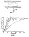
- Figure 2 is a graph of integrated power against core radius for fibres having different values of normalised frequency;
- Figure 3(a) is a graph of refractive index against core radius for a fibre made in accordance with a first aspect of the invention;
- Figure 3(b) is a diagram associated with Figure 3(a) giving figures for the deposited layers at various radial distances; and
- Figure 4 is a graph of loss per unit length against transmitted wavelength for a number of fibres.
- In the process know as the MCVD (modified chemical vapour deposition) process, low loss optical fibres are produced from a solid preform. The preform itself is formed by collapsing a tubular substrate on the inside of which layers of material are deposited by thermal oxidation of chemical vapours. The deposited material is in the form of the solid products of the vapour phase reaction which becomes sintered to a glass layer during the traverse of the heat source.
- Referring to Figure 1, a
substrate tube 1 is formed from pure silica and is rotated about its axis over a source of heat, typically an oxy-hydrogen burner. Combinations of vapours are introduced at one end of the tube and the heater is moved slowly in the direction of vapour flow. The vapour is primarily Sicl4 but includes chlorides of the dopant substances such as GeCl4 and POCl3. Oxidation of the vapour causessolid products 2 to be deposited inside the tube in a region adjacent the source of heat. The actual deposition mechanism lies between a deposition of soot formed in the vapour and the mechanism of the unmodified process where the solid products are deposited where the hot vapour contacts the less hot region of the substrate tube adjacent the heat source. As the heater passes these regions the deposited material is sintered to form aglass layer 3. - As was discussed above the use of pure silica as the cladding material whilst desirable in some respects causes problems as a result of the high temperature required in subsequent stages. Thus a refractive-index-compensated combination of P2O5 and F dopants is desirable in the deposited layers of cladding to reduce the temperature required.
- In a single-mode fibre which is required to have a low loss at both 1.3µm and 1.6µm, the LP11 mode of propogation preferably has a cut off at a wavelength between 1.1 to 1.2µm. To achieve this the normalised frequency V, given by the expression:-

has a value of ~2.2 at 1.3µm and ~1.8 at 1.6µm. Figure 2 shows the integrated power profiles of a step-index single-mode fibre as a function of fibre radius for different values of V, from which it can be seen that for V = 1.8 only ~67% of the power is contained in the core region, whereas~88% of the power is containedwithin a radius of 1.5a and ~96% within a radius of 2a.. - Therefore, if the cladding dopants can be diminished or eliminated out to a radius 1.5a or 2a then the effect of the P-OH and P-0 bonds can be greatly reduced.
- Accordingly, in this method the composition cf the vapour at the beginning of the deposition includes F and POCl3 together with the major component, SiCl4, until 49 layers of cladding are deposited between radii of 5a and 1.5a. This is illustrated in Figures 3(a) and (b). The supply of doping vapours is then extinguished so that 7 layers of pure SiO2 are deposited in the region between radii a to 1.5a. Finally GeCl4 is added to the vapour to deposit the 4 layers comprising the core. A deposition temperature for the pure SiO2 inner cladding that is 200°C greater than that for the doped cladding has been found to be satisfactory, and a deposition rate for the doped cladding of 4 times that for the pure SiO2 region was also found to be suitable.
- In this example the radial thickness of the pure silica layer is limited to 0.5a to minimise the heating required and hence to minimise the possibility of serious distortion of the substrate tube. Further advantageous extension outwards of the pure silica layer may be possible but is likely to require pressurisation to reduce distortion of the substrate. Alternatively the concentration of the compensated dopants maybe gradated in the region adjacent the pure silica layer, so that a compromise between the reduction of P2O5 and the increase in deposition temperature obtains. In a further alternative the concentration of the compensated dopants in the cladding may be gradually diminished in a direction toward the core without being eliminated, and so without a pure silica layer being formed.
- Once the deposition is complete the temperature is increased to 1,700-1,900°C to cause the collapse of, the tube to a solid preform. In accordance with the second'aspect of the invention chlorine gas is introduced upon the termination of the deposition stage and then continued during the collapse stage. This chlorine vapour is of similar high purity to the other materials used and has been found by the inventors to have a significant drying effect at this stage in the process. During the collapse stage -OH concentration tends to increase in the tube material, particularly at the exposed, most recently deposited, core layers. This may be due to absorbtion from any remaining hydrogen containing impurities in the carrier gas or by back diffusion. It will be appreciated that this contamination is particularly important in monomode fibres where the transmitted power is concentrated at the centre of the fibre.
- Figure 4 illustrates the loss spectra of three lengths of fibres produced by collapsing the substrate tube and drawing the fibre in one operation, and in which procedure, during the collapse of the preform tube, chlorine was used as a drying agent. The -OH content estimated from the peaks at 1.25µm in long fibre lengths and from measurements at 1.39µm made on 1km lengths of fibres was 30 to 100 parts in 109. The intensity of the -OH overtone at 1.39µm has been reduced to <3dB/km, and further reduction should be possible.
- Although in the method described, the chlorine used.as a drying agent is introduced as chlorine gas, it could also be obtained from the decomposition of a vapour, such as thionyl chloride which decomposes without causing further deposition. Vapours, such as SiCl4, may also be used and supply may then be continued from the deposition stage, but in such a case the extra deposition of vitreous layers must be accommodated.
Claims (12)
Priority Applications (2)
| Application Number | Priority Date | Filing Date | Title |
|---|---|---|---|
| DE8484115975T DE3176867D1 (en) | 1980-07-17 | 1981-07-16 | A monomode optical fibre and a method of manufacture |
| AT81303273T ATE45718T1 (en) | 1980-07-17 | 1981-07-16 | GLASS FIBERS FOR OPTICAL TRANSMISSION. |
Applications Claiming Priority (2)
| Application Number | Priority Date | Filing Date | Title |
|---|---|---|---|
| GB8023360 | 1980-07-17 | ||
| GB8023360 | 1980-07-17 |
Related Child Applications (2)
| Application Number | Title | Priority Date | Filing Date |
|---|---|---|---|
| EP84115975A Division EP0154026B1 (en) | 1980-07-17 | 1981-07-16 | A monomode optical fibre and a method of manufacture |
| EP84115975.9 Division-Into | 1981-07-16 |
Publications (3)
| Publication Number | Publication Date |
|---|---|
| EP0044712A2 true EP0044712A2 (en) | 1982-01-27 |
| EP0044712A3 EP0044712A3 (en) | 1982-08-04 |
| EP0044712B1 EP0044712B1 (en) | 1989-08-23 |
Family
ID=10514833
Family Applications (2)
| Application Number | Title | Priority Date | Filing Date |
|---|---|---|---|
| EP84115975A Expired EP0154026B1 (en) | 1980-07-17 | 1981-07-16 | A monomode optical fibre and a method of manufacture |
| EP81303273A Expired EP0044712B1 (en) | 1980-07-17 | 1981-07-16 | Improvements in and relating to glass fibres for optical communication |
Family Applications Before (1)
| Application Number | Title | Priority Date | Filing Date |
|---|---|---|---|
| EP84115975A Expired EP0154026B1 (en) | 1980-07-17 | 1981-07-16 | A monomode optical fibre and a method of manufacture |
Country Status (5)
| Country | Link |
|---|---|
| US (1) | US4675038A (en) |
| EP (2) | EP0154026B1 (en) |
| AT (1) | ATE37100T1 (en) |
| CA (1) | CA1149653A (en) |
| DE (1) | DE3177089D1 (en) |
Cited By (4)
| Publication number | Priority date | Publication date | Assignee | Title |
|---|---|---|---|---|
| GB2138416A (en) * | 1983-04-15 | 1984-10-24 | Standard Telephones Cables Ltd | Optical fibre preform manufacture |
| EP0181595A2 (en) * | 1984-11-15 | 1986-05-21 | Polaroid Corporation | Dielectric waveguide with chlorine dopant |
| EP0198118B1 (en) * | 1985-03-20 | 1990-05-09 | Licentia Patent-Verwaltungs-GmbH | Silica glass single-mode optical fibre and its production method |
| FR2679548A1 (en) * | 1991-07-25 | 1993-01-29 | Alsthom Cge Alcatel | PROCESS FOR PRODUCING ACTIVE OPTICAL FIBERS. |
Families Citing this family (18)
| Publication number | Priority date | Publication date | Assignee | Title |
|---|---|---|---|---|
| KR900003449B1 (en) * | 1986-06-11 | 1990-05-19 | 스미도모덴기고오교오 가부시기가이샤 | Dispersion-shift fiber and its production |
| US5055120A (en) * | 1987-12-15 | 1991-10-08 | Infrared Fiber Systems, Inc. | Fluoride glass fibers with reduced defects |
| DE3820217A1 (en) * | 1988-06-14 | 1989-12-21 | Rheydt Kabelwerk Ag | Optical waveguide, especially monomode fibre |
| DE3842804A1 (en) * | 1988-12-20 | 1990-06-21 | Rheydt Kabelwerk Ag | Optical waveguide |
| DE3842805A1 (en) * | 1988-12-20 | 1990-06-21 | Rheydt Kabelwerk Ag | Optical waveguide |
| DE3938386A1 (en) * | 1989-11-18 | 1991-05-23 | Rheydt Kabelwerk Ag | Optical waveguide with low attenuation - provided by barrier layer between cladding tube and optically active region |
| AU649845B2 (en) * | 1991-06-24 | 1994-06-02 | Sumitomo Electric Industries, Ltd. | Method for producing glass preform for optical fiber |
| US5522003A (en) * | 1993-03-02 | 1996-05-28 | Ward; Robert M. | Glass preform with deep radial gradient layer and method of manufacturing same |
| US5641333A (en) * | 1995-12-01 | 1997-06-24 | Corning Incorporated | Increasing the retention of Ge02 during production of glass articles |
| US6131415A (en) * | 1997-06-20 | 2000-10-17 | Lucent Technologies Inc. | Method of making a fiber having low loss at 1385 nm by cladding a VAD preform with a D/d<7.5 |
| RU2156485C1 (en) * | 1999-05-19 | 2000-09-20 | Научный центр волоконной оптики при Институте общей физики РАН | Photosensitive fibre-optic light conduit and photoinduced structure |
| US6574406B2 (en) | 2001-09-11 | 2003-06-03 | Corning Incorporated | Selectively absorbing optical fibers for optical amplifiers |
| WO2003057634A1 (en) * | 2001-12-21 | 2003-07-17 | Fibercore, Inc. | Method for offline collapsing a preform |
| NL1021992C2 (en) * | 2002-11-26 | 2004-05-27 | Draka Fibre Technology Bv | Rod in tube process for preparing optical fibre preform, by heating rod and mantle separated by cavity containing deuterium |
| NL1024480C2 (en) * | 2003-10-08 | 2005-04-11 | Draka Fibre Technology Bv | Method for manufacturing an optical fiber preform, as well as method for manufacturing optical fibers. |
| US7805039B2 (en) * | 2007-05-04 | 2010-09-28 | Weatherford/Lamb, Inc. | Single mode optical fiber with improved bend performance |
| NL2004874C2 (en) | 2010-06-11 | 2011-12-19 | Draka Comteq Bv | METHOD FOR MANUFACTURING A PRIMARY FORM |
| NL2014519B1 (en) | 2015-03-25 | 2017-01-25 | Draka Comteq Bv | A rotary feed-through for mounting a rotating substrate tube in a lathe, a CVD lathe and a corresponding method using the CVD lathe. |
Citations (5)
| Publication number | Priority date | Publication date | Assignee | Title |
|---|---|---|---|---|
| CA1034818A (en) * | 1975-04-16 | 1978-07-18 | Northern Electric Company Limited | Manufacture of optical fibres |
| FR2418775A1 (en) * | 1976-12-20 | 1979-09-28 | Corning Glass Works | PROCESS FOR THE REALIZATION OF OPTICAL WAVE GUIDES |
| JPS54160826A (en) * | 1978-06-08 | 1979-12-19 | Nippon Telegr & Teleph Corp <Ntt> | Fiber for optical communication |
| DE2623989B2 (en) * | 1976-05-28 | 1980-05-29 | Licentia Patent-Verwaltungs-Gmbh, 6000 Frankfurt | Single mode light guide |
| EP0041864A2 (en) * | 1980-06-09 | 1981-12-16 | Corning Glass Works | Long wavelength, low-loss optical waveguide |
Family Cites Families (8)
| Publication number | Priority date | Publication date | Assignee | Title |
|---|---|---|---|---|
| GB1562032A (en) * | 1977-03-24 | 1980-03-05 | Standard Telephones Cables Ltd | Optical fibre manufacture |
| US4334903A (en) * | 1977-08-29 | 1982-06-15 | Bell Telephone Laboratories, Incorporated | Optical fiber fabrication |
| US4165223A (en) * | 1978-03-06 | 1979-08-21 | Corning Glass Works | Method of making dry optical waveguides |
| JPS5852935B2 (en) * | 1978-11-20 | 1983-11-26 | 三菱マテリアル株式会社 | Manufacturing method for optical transmission materials |
| JPS5924092B2 (en) * | 1978-12-29 | 1984-06-07 | 三菱マテリアル株式会社 | Manufacturing method of optical fiber base material |
| US4304583A (en) * | 1980-06-02 | 1981-12-08 | Corning Glass Works | Process for drying optical waveguide preforms |
| US4286978A (en) * | 1980-07-03 | 1981-09-01 | Corning Glass Works | Method for substantially continuously drying, consolidating and drawing an optical waveguide preform |
| US4298634A (en) * | 1980-11-04 | 1981-11-03 | Compagnie Internationale Pour L'informatique Cii-Honeywell Bull (Societe Anonyme) | Method for coating cylindrical surfaces |
-
1981
- 1981-07-16 EP EP84115975A patent/EP0154026B1/en not_active Expired
- 1981-07-16 CA CA000381845A patent/CA1149653A/en not_active Expired
- 1981-07-16 AT AT84115975T patent/ATE37100T1/en not_active IP Right Cessation
- 1981-07-16 EP EP81303273A patent/EP0044712B1/en not_active Expired
- 1981-07-16 DE DE8181303273T patent/DE3177089D1/en not_active Expired
-
1986
- 1986-04-21 US US06/856,841 patent/US4675038A/en not_active Expired - Lifetime
Patent Citations (5)
| Publication number | Priority date | Publication date | Assignee | Title |
|---|---|---|---|---|
| CA1034818A (en) * | 1975-04-16 | 1978-07-18 | Northern Electric Company Limited | Manufacture of optical fibres |
| DE2623989B2 (en) * | 1976-05-28 | 1980-05-29 | Licentia Patent-Verwaltungs-Gmbh, 6000 Frankfurt | Single mode light guide |
| FR2418775A1 (en) * | 1976-12-20 | 1979-09-28 | Corning Glass Works | PROCESS FOR THE REALIZATION OF OPTICAL WAVE GUIDES |
| JPS54160826A (en) * | 1978-06-08 | 1979-12-19 | Nippon Telegr & Teleph Corp <Ntt> | Fiber for optical communication |
| EP0041864A2 (en) * | 1980-06-09 | 1981-12-16 | Corning Glass Works | Long wavelength, low-loss optical waveguide |
Non-Patent Citations (7)
| Title |
|---|
| Applied Physics Letters, Vol. 31, No. 8, 15th October 1977, pages 515-517 T. AKAMATSU et al.: "Fabrication of Graded-Index Fibers Without an Index Dip by Chemical Vapor Deposition Method". * |
| CHEMICAL ABSTRACTS, Vol. 93, No. 2, 14th July 1980, page 265, column, 1, Abstract No. 12320n, Columbus, Ohio, U.S.A. & JP-A-54 160 826 (Nippon Telegraph and Telephone) 19-12-1979 * |
| Electronics Letters, Vol. 15, No. 15, 5th july 1979, pages 411-413 B.J. AINSLIE ey al.: "Preparation of Long Lengths of Ultra-Low-Loss Single-Mode Fibre". * |
| Electronics Letters, Vol. 15, No. 25, 6th December 1979, pages 835-836 K. CHIDA et al.: "Simultaneous Dehydration with Consolidation for V.A.D. method". * |
| Electronics Letters, Vol. 16, No. 18, 28th August 1980, pages 692-693 B.J. AINSLIE et al.: "Optimised Structure for Preparing Long Ultra-Low-Loss Single-Mode Fibres". * |
| Optical Communication Conference, 17th-19th September 1979, pages 5.4.1 - 5.4.4, Conference Proceedings, Amsterdam, NL. H. YOKOTA et al: "Long-Lenght Single-Mode fiber with Low Attenuation in the Dispersion free Region". * |
| Optical Fiber Communications, march 1979, WC 6 * |
Cited By (6)
| Publication number | Priority date | Publication date | Assignee | Title |
|---|---|---|---|---|
| GB2138416A (en) * | 1983-04-15 | 1984-10-24 | Standard Telephones Cables Ltd | Optical fibre preform manufacture |
| EP0181595A2 (en) * | 1984-11-15 | 1986-05-21 | Polaroid Corporation | Dielectric waveguide with chlorine dopant |
| EP0181595A3 (en) * | 1984-11-15 | 1986-08-06 | Polaroid Corporation | Dielectric waveguide with chlorine dopant |
| EP0198118B1 (en) * | 1985-03-20 | 1990-05-09 | Licentia Patent-Verwaltungs-GmbH | Silica glass single-mode optical fibre and its production method |
| FR2679548A1 (en) * | 1991-07-25 | 1993-01-29 | Alsthom Cge Alcatel | PROCESS FOR PRODUCING ACTIVE OPTICAL FIBERS. |
| US5364429A (en) * | 1991-07-25 | 1994-11-15 | Alcatel Fibres Optiques | Method of manufacturing active optical fibers |
Also Published As
| Publication number | Publication date |
|---|---|
| EP0154026A3 (en) | 1985-11-27 |
| CA1149653A (en) | 1983-07-12 |
| DE3177089D1 (en) | 1989-09-28 |
| EP0044712B1 (en) | 1989-08-23 |
| EP0154026A2 (en) | 1985-09-11 |
| EP0044712A3 (en) | 1982-08-04 |
| ATE37100T1 (en) | 1988-09-15 |
| EP0154026B1 (en) | 1988-09-07 |
| US4675038A (en) | 1987-06-23 |
Similar Documents
| Publication | Publication Date | Title |
|---|---|---|
| EP0044712A2 (en) | Improvements in and relating to glass fibres for optical communication | |
| US3932162A (en) | Method of making glass optical waveguide | |
| US4385802A (en) | Long wavelength, low-loss optical waveguide | |
| US4822399A (en) | Glass preform for dispersion shifted single mode optical fiber and method for the production of the same | |
| US4339174A (en) | High bandwidth optical waveguide | |
| US4787927A (en) | Fabrication of optical fibers | |
| US4468413A (en) | Method of manufacturing fluorine-doped optical fibers | |
| US4314833A (en) | Method of producing optical fibers | |
| EP0139348B1 (en) | Optical fiber and method for its production | |
| AU645089B2 (en) | Wave-guiding structure with lasing properties | |
| EP0198510B1 (en) | Method of producing glass preform for optical fiber | |
| US4802733A (en) | Fluorine-doped optical fibre and method of manufacturing such fibre | |
| US4335934A (en) | Single mode fibre and method of making | |
| US4206968A (en) | Optical fiber and method for producing the same | |
| US5221308A (en) | Low loss infrared transmitting hollow core optical fiber method of manufacture | |
| US4747663A (en) | Monomode quartz glass light waveguide and method for producing it | |
| WO2002088041A1 (en) | Low-loss highly phosphorus-doped fibers for raman amplification | |
| CA1171703A (en) | Glass fibres for optical communications | |
| JPH0476936B2 (en) | ||
| GB2046239A (en) | Optical fibres | |
| CA1246875A (en) | Process for eliminating the axial refractive index depression in optical fibres | |
| JPH0820574B2 (en) | Dispersion shift fiber and manufacturing method thereof | |
| JP3343079B2 (en) | Optical fiber core member, optical fiber preform, and method of manufacturing the same | |
| EP0185975A1 (en) | Process for fabricating a glass preform | |
| GB1593488A (en) | Low loss high n a plastic clad optical fibres |
Legal Events
| Date | Code | Title | Description |
|---|---|---|---|
| PUAI | Public reference made under article 153(3) epc to a published international application that has entered the european phase |
Free format text: ORIGINAL CODE: 0009012 |
|
| AK | Designated contracting states |
Designated state(s): AT BE CH DE FR GB IT LU NL SE |
|
| PUAL | Search report despatched |
Free format text: ORIGINAL CODE: 0009013 |
|
| AK | Designated contracting states |
Designated state(s): AT BE CH DE FR GB IT LU NL SE |
|
| 17P | Request for examination filed |
Effective date: 19830201 |
|
| RAP1 | Party data changed (applicant data changed or rights of an application transferred) |
Owner name: THE POST OFFICE |
|
| RAP1 | Party data changed (applicant data changed or rights of an application transferred) |
Owner name: BRITISH TELECOMMUNICATIONS PUBLIC LIMITED COMPANY |
|
| GRAA | (expected) grant |
Free format text: ORIGINAL CODE: 0009210 |
|
| AK | Designated contracting states |
Kind code of ref document: B1 Designated state(s): AT BE CH DE FR GB IT LI LU NL SE |
|
| REF | Corresponds to: |
Ref document number: 45718 Country of ref document: AT Date of ref document: 19890915 Kind code of ref document: T |
|
| ITF | It: translation for a ep patent filed |
Owner name: JACOBACCI & PERANI S.P.A. |
|
| REF | Corresponds to: |
Ref document number: 3177089 Country of ref document: DE Date of ref document: 19890928 |
|
| ET | Fr: translation filed | ||
| RAP4 | Party data changed (patent owner data changed or rights of a patent transferred) |
Owner name: BRITISH TELECOMMUNICATIONS PUBLIC LIMITED COMPANY |
|
| PLBE | No opposition filed within time limit |
Free format text: ORIGINAL CODE: 0009261 |
|
| STAA | Information on the status of an ep patent application or granted ep patent |
Free format text: STATUS: NO OPPOSITION FILED WITHIN TIME LIMIT |
|
| 26N | No opposition filed | ||
| ITTA | It: last paid annual fee | ||
| EPTA | Lu: last paid annual fee | ||
| EAL | Se: european patent in force in sweden |
Ref document number: 81303273.7 |
|
| PGFP | Annual fee paid to national office [announced via postgrant information from national office to epo] |
Ref country code: AT Payment date: 20000612 Year of fee payment: 20 |
|
| REG | Reference to a national code |
Ref country code: GB Ref legal event code: 732E |
|
| PGFP | Annual fee paid to national office [announced via postgrant information from national office to epo] |
Ref country code: SE Payment date: 20000620 Year of fee payment: 20 |
|
| PGFP | Annual fee paid to national office [announced via postgrant information from national office to epo] |
Ref country code: FR Payment date: 20000621 Year of fee payment: 20 Ref country code: CH Payment date: 20000621 Year of fee payment: 20 |
|
| PGFP | Annual fee paid to national office [announced via postgrant information from national office to epo] |
Ref country code: GB Payment date: 20000622 Year of fee payment: 20 |
|
| PGFP | Annual fee paid to national office [announced via postgrant information from national office to epo] |
Ref country code: NL Payment date: 20000627 Year of fee payment: 20 |
|
| PGFP | Annual fee paid to national office [announced via postgrant information from national office to epo] |
Ref country code: DE Payment date: 20000629 Year of fee payment: 20 |
|
| PGFP | Annual fee paid to national office [announced via postgrant information from national office to epo] |
Ref country code: BE Payment date: 20000704 Year of fee payment: 20 |
|
| PGFP | Annual fee paid to national office [announced via postgrant information from national office to epo] |
Ref country code: LU Payment date: 20000712 Year of fee payment: 20 |
|
| BE20 | Be: patent expired |
Free format text: 20010716 *BRITISH TELECOMMUNICATIONS P.L.C. |
|
| PG25 | Lapsed in a contracting state [announced via postgrant information from national office to epo] |
Ref country code: LI Free format text: LAPSE BECAUSE OF EXPIRATION OF PROTECTION Effective date: 20010715 Ref country code: GB Free format text: LAPSE BECAUSE OF EXPIRATION OF PROTECTION Effective date: 20010715 Ref country code: CH Free format text: LAPSE BECAUSE OF EXPIRATION OF PROTECTION Effective date: 20010715 |
|
| PG25 | Lapsed in a contracting state [announced via postgrant information from national office to epo] |
Ref country code: NL Free format text: LAPSE BECAUSE OF EXPIRATION OF PROTECTION Effective date: 20010716 Ref country code: LU Free format text: LAPSE BECAUSE OF EXPIRATION OF PROTECTION Effective date: 20010716 Ref country code: AT Free format text: LAPSE BECAUSE OF EXPIRATION OF PROTECTION Effective date: 20010716 |
|
| PG25 | Lapsed in a contracting state [announced via postgrant information from national office to epo] |
Ref country code: SE Free format text: THE PATENT HAS BEEN ANNULLED BY A DECISION OF A NATIONAL AUTHORITY Effective date: 20010730 |
|
| REG | Reference to a national code |
Ref country code: GB Ref legal event code: PE20 Effective date: 20010715 |
|
| REG | Reference to a national code |
Ref country code: CH Ref legal event code: PL |
|
| NLV7 | Nl: ceased due to reaching the maximum lifetime of a patent |
Effective date: 20010716 |
|
| EUG | Se: european patent has lapsed |
Ref document number: 81303273.7 |