EP0044403A2 - Method for the measurement of fuel consumption - Google Patents
Method for the measurement of fuel consumption Download PDFInfo
- Publication number
- EP0044403A2 EP0044403A2 EP81104534A EP81104534A EP0044403A2 EP 0044403 A2 EP0044403 A2 EP 0044403A2 EP 81104534 A EP81104534 A EP 81104534A EP 81104534 A EP81104534 A EP 81104534A EP 0044403 A2 EP0044403 A2 EP 0044403A2
- Authority
- EP
- European Patent Office
- Prior art keywords
- consumption
- evaluation circuit
- value
- intake manifold
- function
- Prior art date
- Legal status (The legal status is an assumption and is not a legal conclusion. Google has not performed a legal analysis and makes no representation as to the accuracy of the status listed.)
- Withdrawn
Links
Images
Classifications
-
- G—PHYSICS
- G01—MEASURING; TESTING
- G01D—MEASURING NOT SPECIALLY ADAPTED FOR A SPECIFIC VARIABLE; ARRANGEMENTS FOR MEASURING TWO OR MORE VARIABLES NOT COVERED IN A SINGLE OTHER SUBCLASS; TARIFF METERING APPARATUS; MEASURING OR TESTING NOT OTHERWISE PROVIDED FOR
- G01D1/00—Measuring arrangements giving results other than momentary value of variable, of general application
- G01D1/16—Measuring arrangements giving results other than momentary value of variable, of general application giving a value which is a function of two or more values, e.g. product or ratio
-
- G—PHYSICS
- G01—MEASURING; TESTING
- G01F—MEASURING VOLUME, VOLUME FLOW, MASS FLOW OR LIQUID LEVEL; METERING BY VOLUME
- G01F1/00—Measuring the volume flow or mass flow of fluid or fluent solid material wherein the fluid passes through a meter in a continuous flow
- G01F1/05—Measuring the volume flow or mass flow of fluid or fluent solid material wherein the fluid passes through a meter in a continuous flow by using mechanical effects
- G01F1/34—Measuring the volume flow or mass flow of fluid or fluent solid material wherein the fluid passes through a meter in a continuous flow by using mechanical effects by measuring pressure or differential pressure
- G01F1/36—Measuring the volume flow or mass flow of fluid or fluent solid material wherein the fluid passes through a meter in a continuous flow by using mechanical effects by measuring pressure or differential pressure the pressure or differential pressure being created by the use of flow constriction
- G01F1/363—Measuring the volume flow or mass flow of fluid or fluent solid material wherein the fluid passes through a meter in a continuous flow by using mechanical effects by measuring pressure or differential pressure the pressure or differential pressure being created by the use of flow constriction with electrical or electro-mechanical indication
-
- G—PHYSICS
- G01—MEASURING; TESTING
- G01F—MEASURING VOLUME, VOLUME FLOW, MASS FLOW OR LIQUID LEVEL; METERING BY VOLUME
- G01F9/00—Measuring volume flow relative to another variable, e.g. of liquid fuel for an engine
- G01F9/008—Measuring volume flow relative to another variable, e.g. of liquid fuel for an engine where the other variable is the flight or running time
-
- G—PHYSICS
- G01—MEASURING; TESTING
- G01F—MEASURING VOLUME, VOLUME FLOW, MASS FLOW OR LIQUID LEVEL; METERING BY VOLUME
- G01F9/00—Measuring volume flow relative to another variable, e.g. of liquid fuel for an engine
- G01F9/02—Measuring volume flow relative to another variable, e.g. of liquid fuel for an engine wherein the other variable is the speed of a vehicle
- G01F9/023—Measuring volume flow relative to another variable, e.g. of liquid fuel for an engine wherein the other variable is the speed of a vehicle with electric, electro-mechanic or electronic means
Definitions
- the invention relates to a method for measuring the fuel consumption of a motor vehicle equipped with an Otto engine.
- two sensors are used in a fuel line leading to the carburetor of the internal combustion engine, namely a sensor for detecting the fuel flowing to the carburetor and a second sensor for detecting the fuel return flow.
- the actual fuel consumption is determined by forming the difference between the values displayed by the two sensors.
- the installation of two sensors is quite complex.
- the invention has for its object to provide a much easier to implement method.
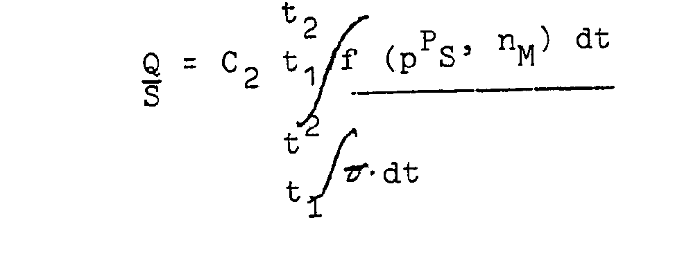
- Have measurements of the fuel consumption maps of various types of carburetor engines used in motor vehicles shown that an evaluation of the instantaneous fuel consumption q can be derived according to the invention from the intake manifold pressure p S and the engine speed n M with sufficient accuracy, where q C. (p S - p 0 ). n M is set.
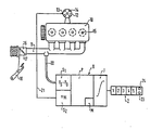
- FIG. 11 A particularly simple exemplary embodiment for carrying out the method according to the invention is shown in the drawing.
- 11 the intake pipe of a four-cylinder, four-stroke internal combustion engine 10, the ignition distributor 12 of which has a low-voltage connection 13 (terminal 1) and is on its high-voltage electrodes 14 with the spark plugs 15 of the internal combustion engine via ignition cables, not shown.
- the intake manifold 11 leads from the carburetor indicated at 16, which is not shown in detail, the throttle valve 17 of which can be adjusted by means of an accelerator pedal 18, to the individual cylinders of the internal combustion engine 10.
- the measuring and evaluation device G contains two sensors, namely a pressure sensor S1 connected to the intake pipe 11 via a hose line 20, which detects the intake pipe pressure p which prevails in the intake pipe 11 and is dependent on the position of the throttle valve 17 and the engine speed S is determined and, for shifting the characteristic curve, forms the difference compared to a comparison value p 0 .
- the second sensor S2 is used to determine the respective speed n M of the internal combustion engine and is connected to the distribution terminal 13 via an electrical line 21.
- the constant C depends on that engine and vehicle type and can be taken into account by means of an insertable module M. In this way it is possible to provide a common evaluation device for different types of motor vehicles.
- the integration can be started using a start button 23 and stopped using a stop button 24.
- claims 3, 6, 12, 16, 17, 22, 23, 24 and 25 and 29 are particularly realized.
- the possibility of placing the pressure sensor in the evaluation circuit reduces the demands on the pressure sensor with regard to resistance to shaking and the temperature range and saves a sensor housing.
- the "sensor” engine speed is realized by an extended evaluation circuit.
- the additional driving speed sensor is useful if consumption values related to the route are to be displayed immediately and are not to be calculated by the driver using the odometer on the speedometer.
- This arrangement of the factor-determining components makes it possible to produce a uniform measuring system for many types of motor vehicles, in which case only this module has to be used for the specific type of motor vehicle.
- the pressure system according to the invention can subsequently be easily and quickly connected to any existing system (connection to the intake manifold pressure) and does not require any changes to the existing metering systems.
- the pressure measuring system can be retrofitted.
- the installation of systems with intervention in the gasoline line is much more difficult for laymen and workshops.
- the two sensors, pressure sensor and engine speed sensor can be integrated into the evaluation circuit.
Abstract
Description
Die Erfindung betrifft ein Verfahren zur Messung des Kraftstoffverbrauchs eines mit einem Otto-Motor ausgerüsteten Kraftfahrzeugs.The invention relates to a method for measuring the fuel consumption of a motor vehicle equipped with an Otto engine.
Bei bekannten Verfahren zur Verbrauchsmessung werden in einer zum Vergaser der Brennkraftmaschine führenden Kraftstoffleitung zwei Sensoren verwendet, nämlich ein Sensor zur Erfassung des dem Vergaser zufließenden Kraftstoffs und ein zweiter Sensor zur Erfassung des Kraftstoffrückflusses. Der tatsächliche Verbrauch des Kraftstoffs wird durch Differenzbildung der von den beiden Sensoren angezeigten Werte ermittelt. Der Einbau von zwei Sensoren ist ziemlich aufwendig.In known methods for measuring consumption, two sensors are used in a fuel line leading to the carburetor of the internal combustion engine, namely a sensor for detecting the fuel flowing to the carburetor and a second sensor for detecting the fuel return flow. The actual fuel consumption is determined by forming the difference between the values displayed by the two sensors. The installation of two sensors is quite complex.
Der Erfindung liegt die Aufgabe zugrunde ein wesentlich einfacher durchführbares Verfahren zu schaffen. Messungen der Verbrauchskennfelder von verschiedenen, in Kraftfahrzeugen verwendeten Typen von Vergasermotoren haben gezeigt, daß mit ausreichender Genauigkeit eine Auswertung des momentanen Kraftstoffverbrauchs q erfindungsgemäß vom Saugrohrdruck pS und der Motordrehzahl nM abgeleitet werden kann, wobei q = C. (pS - p0). nM gesetzt wird.The invention has for its object to provide a much easier to implement method. Have measurements of the fuel consumption maps of various types of carburetor engines used in motor vehicles shown that an evaluation of the instantaneous fuel consumption q can be derived according to the invention from the intake manifold pressure p S and the engine speed n M with sufficient accuracy, where q = C. (p S - p 0 ). n M is set.
Weitere Ausgestaltungen des erfindungsgemäßen Verfahrens ergeben sich aus den Unteransprüchen.Further refinements of the method according to the invention result from the subclaims.
In der Zeiqhnung ist ein besonders einfaches Ausführungsbeispiel zur Durchführung des erfindungsgemäßen Verfahrens dargestellt. Dort ist mit 11 das Ansaugrohr einer Vierzylinder-Viertakt-Brennkraftmaschine 10 angedeutet, deren Zündverteiler 12 einen Niederspannungsanschluß 13 (Klemme 1) aufweist und an seinen Hochspannungselektroden 14 mit den Zündkerzen 15 der Brennkraftmaschine über nicht dargestellte Zündkabel ist. In der vereinfachten Darstellung der Zeichnung führt das Saugrohr 11 von dem bei 16 angedeuteten, im einzelnen nicht näher wiedergegebenen Vergaser, dessen Drosselklappe 17 mittels eines Gaspedals 18 verstellbar ist, zu den einzelnen Zylindern der Brennkraftmaschine 10.A particularly simple exemplary embodiment for carrying out the method according to the invention is shown in the drawing. There is indicated by 11 the intake pipe of a four-cylinder, four-stroke
Zur Erfassung des Kraftstoffverbrauchs der Brennkraftmaschine 10 enthält das Meß- und Auswertegerät G zwei Sensoren, nämlich einen über eine Schlauchleitung 20 an das Ansaugrohr 11 angeschlossenen Drucksensor S1, der den im Ansaugrohr 11 herrschenden, von der Stellung der Drosselklappe 17 und der Motordrehzahl abhängigen Saugrohrdruck pS ermittelt und zur Kennlinienverschiebung die Differenz gegenüber einem Vergleichswert p0 bildet. Der zweite Sensor S2 dient zur Ermittlung der jeweiligen Drehzahl nM der Brennkraftmaschine und ist über eine elektrische Leitung 21 an die Verteilerklemme 13 angeschlossen. Das Auswertegerät G enthält einen Prozessor P, der in der oben angegebenen Weise das Produkt q = C. (pS - pO). nM bildet. Die Konstante C hängt von dem jeweiligen Motor- und Fahrzeugtyp ab und kann mittels eines einschiebbaren Moduls M berücksichtigt werden. Auf diese Weise ist es möglich, für verschiedene Kraftfahrzeugtypen ein gemeinsames Auswertegerät vorzusehen.To record the fuel consumption of the
Der Prozessor P arbeitet auf einen Integrator I, an welchen eine fünfstellige Digitalanzeige Z angeschlossen ist. Diese zeigt den jeweiligen Kraftstoffverbrauch in Litern (1=dm3) an. Die Integration kann mit Hilfe eines Startknopfes 23 gestartet und mit Hilfe einer Stopptaste 24 gestoppt werden.The processor P works on an integrator I, to which a five-digit digital display Z is connected. This shows the respective fuel consumption in liters (1 = d m 3 ). The integration can be started using a start button 23 and stopped using a
An dem dargestellten Ausführungsbeispiel sind vor allem die Ansprüche 3, 6, 12, 16, 17, 22, 23, 24 und 25 sowie 29 verwirklicht.In the illustrated embodiment, claims 3, 6, 12, 16, 17, 22, 23, 24 and 25 and 29 are particularly realized.
Im einzelnen gibt die am Ausführungsbeispiel erläuterte Erfindung die Möglichkeit, im Kraftfahrzeug einzeln oder in gegenseitiger Kombination eine Anzeige folgender Werte zu bewirken:
- - Integralwert des Verbrauchs in 1
- - Integralwert des auf die Strecke bezogenen Verbrauchs in 1/100 km (1 = 1 dm3 = 1000 cm3)
- - Momentanwert des Verbrauchs in 1/h
- - Momentanwert des auf die Strecke
bezogenen Verbrauchs 1/100km - - Motordrehzahl
- - Fahrgeschwindigkeit und
- - gefahrene Strecke.
- - Integral value of consumption in 1
- - integral value of the consumption related to the distance in 1/100 km (1 = 1 dm 3 = 1000 c m 3 )
- - Current value of consumption in 1 / h
- - Current value of the consumption related to the
route 1 / 100km - - engine speed
- - driving speed and
- - distance traveled.
Nachstehend werden zu einzelnen Ansprüchen noch folgende Erläuterungen gegeben:The following explanations are given below for individual claims:
Die Möglichkeit, den Drucksensor in der Auswerteschaltung zu plazieren, reduziert die Forderungen an den Drucksensor bezüglich Schüttelfestigkeit und Temperaturbereich und spart ein Sensorengehäuse.The possibility of placing the pressure sensor in the evaluation circuit reduces the demands on the pressure sensor with regard to resistance to shaking and the temperature range and saves a sensor housing.
Der "Sensor" Motordrehzahl wird durch eine erweiterte Auswerteschaltung realisiert.The "sensor" engine speed is realized by an extended evaluation circuit.
Der zusätzliche Sensor Fahrgeschwindigkeit ist dann zweckmäßig, wenn auf die Strecke bezogene Verbrauchswerte unmittelbar angezeigt werden sollen und nicht vom Fahrer mittels Kilometerzähler am Tachometer errechnet werden sollen.The additional driving speed sensor is useful if consumption values related to the route are to be displayed immediately and are not to be calculated by the driver using the odometer on the speedometer.
Mit dieser Methode könnte z.B. anstelle des Geschwindigkeitssensors ein Gangschalter eingesetzt werden, was aber vermutlich nicht sehr zweckmäßig wäre.With this method e.g. a gear switch can be used instead of the speed sensor, but this would probably not be very useful.
Diese Möglichkeit erhöht den Wert der Anzeige bedeutend.This option significantly increases the value of the ad.
Wichtig, wenn der integrierte Verbrauch über Tage hinweg z.B. über eine Tankfüllung, gemessen werden soll.This is important if the integrated consumption is to be measured over a period of days, for example over a tank of fuel.
Bei dem hier vorgeschlagenen System ist eine Absolutdruckmessung zweckmäßig. Eine Differenzdruckmessung zur Atmosphäre bringt zusätzliche Fehler.In the system proposed here, an absolute pressure measurement is expedient. A differential pressure measurement to the atmosphere brings additional errors.
Durch diese Anordnung der faktorenbestimmenden Bauteile ist es möglich, ein einheitliches Meßsystem für viele Kfz-Typen zu produzieren, bei welchem dann nur dieser Modul kraftfahrzeugtypspezifisch eingesetzt werden muß.This arrangement of the factor-determining components makes it possible to produce a uniform measuring system for many types of motor vehicles, in which case only this module has to be used for the specific type of motor vehicle.
Das erfindungsgemäße Meßverfahren hat im Vergleich zu Meßverfahren mit Durchflußmessern folgende Vorteile:
- Die Durchflußmessung muß über einen Bereich 1 : 40 erfolgen. Die Druckmessung im Saugrohr über 1:5 ist verbunden mit einer Drehzahlmessung 1 : 8, welche absolut unproblematisch ist.
- The flow measurement must take place over a range 1:40. The pressure measurement in the intake manifold above 1: 5 is connected to a speed measurement 1: 8, which is absolutely unproblematic.
Bei vielen Zumeßsystemen (z.B. bei Vergasern mit Rücklaufleitungen) müssen zwei Durchflußsensoren eingebaut werden und das Differenzsignal zweier großer Durchflüsse muß ausgewertet werden. Das erhöht die Kosten und verschlechtert die Meßgenauigkeit. Beim Saugrohrdrucksystem können alle Kfz-Typen durch ein oder wenige Meßsystemtypen abgedeckt werden, wenn nur in der Auswerteschaltung entsprechend Anspruch 29 kraftfahrzeugtypspezifische Module vorgesehen werden.In many metering systems (e.g. carburettors with return lines) two flow sensors must be installed and the difference signal of two large flows must be evaluated. This increases costs and worsens measurement accuracy. When Saugrohrdrucksystem all car types by one or a few Meßsystemtypen be covered if only be provided in the evaluation circuit according to claim 29 kraftfahrzeugty p-specific modules.
Dies ist auch deshalb von Vorteil, weil alle Kfz-Typen einen einheitlichen Saugrohrdruckbereich 0,2 bis 1 bar besitzen, während der Durchflußmeßbereich bei verschieden großen Motoren mit der Leistung variiert. D.h. fast alle Kfz-Typen können mit einem einzigen Druckgebertyp abgedeckt werden; bei Durchflußmessern müßte eine Typenreihe abgestuft nach verschieden großen Motoren produziert werden.This is also advantageous because all types of motor vehicles have a uniform intake manifold pressure range of 0.2 to 1 bar, while the flow measurement range varies with the power of differently sized engines. I.e. almost all types of motor vehicles can be covered with a single pressure sensor type; in the case of flowmeters, a series of types would have to be produced graded according to different sized motors.
Der Einbau eines Durchflußmessers bedeutet für den Motorenhersteller eine Beeinträchtigung der Zumeßanlage mit zusätzlichen Problemen und einer Umkonstruktion der Zumeßanlage.The installation of a flow meter means for the motor manufacturer an impairment of the metering system with additional problems and a redesign of the metering system.
Das erfindungsgemäße Drucksystem kann nachträglich problemlos und schnell auf jedes vorhandene System (Anschluß am Saugrohrdruck) aufgeschaltet werden und bedingt keinerlei Veränderungen an den vorhandenen Zumeßsystemen.The pressure system according to the invention can subsequently be easily and quickly connected to any existing system (connection to the intake manifold pressure) and does not require any changes to the existing metering systems.
Das Druckmeßsystem ist nachrüstbar. Der Einbau von Systemen mit Eingriff in die Benzinleitung ist für Laien und Werkstätten wesentlich schwieriger.The pressure measuring system can be retrofitted. The installation of systems with intervention in the gasoline line is much more difficult for laymen and workshops.
Die beiden Sensoren Druckgeber und Motordrehzahlgeber können in die Auswerteschaltung integriert werden.The two sensors, pressure sensor and engine speed sensor, can be integrated into the evaluation circuit.
Claims (30)
der Motordrehzahl nM
abgeleitet wird.
the engine speed n M
is derived.


Applications Claiming Priority (2)
| Application Number | Priority Date | Filing Date | Title |
|---|---|---|---|
| DE19803027470 DE3027470A1 (en) | 1980-07-19 | 1980-07-19 | METHOD FOR MEASURING FUEL CONSUMPTION |
| DE3027470 | 1980-07-19 |
Publications (2)
| Publication Number | Publication Date |
|---|---|
| EP0044403A2 true EP0044403A2 (en) | 1982-01-27 |
| EP0044403A3 EP0044403A3 (en) | 1984-07-04 |
Family
ID=6107641
Family Applications (1)
| Application Number | Title | Priority Date | Filing Date |
|---|---|---|---|
| EP81104534A Withdrawn EP0044403A3 (en) | 1980-07-19 | 1981-06-12 | Method for the measurement of fuel consumption |
Country Status (3)
| Country | Link |
|---|---|
| EP (1) | EP0044403A3 (en) |
| JP (1) | JPS5752821A (en) |
| DE (1) | DE3027470A1 (en) |
Cited By (1)
| Publication number | Priority date | Publication date | Assignee | Title |
|---|---|---|---|---|
| GB2127545A (en) * | 1982-07-28 | 1984-04-11 | Univ Open | Fuel consumption indicator and travel cost display system |
Families Citing this family (3)
| Publication number | Priority date | Publication date | Assignee | Title |
|---|---|---|---|---|
| EP0094370A3 (en) * | 1982-04-28 | 1985-08-21 | Ing. Franz Mitterbauer Gesellschaft m.b.H. & Co. KG. | Device for determining the fuel consumption of an internal-combustion engine |
| DE3245546A1 (en) * | 1982-12-09 | 1984-06-14 | Bosch und Pierburg System oHG, 4040 Neuss | Device for determining the instantaneous fuel consumption of internal combustion engines |
| JPS6062931A (en) * | 1983-09-09 | 1985-04-11 | 泰東製綱株式会社 | Leader of set net |
Citations (5)
| Publication number | Priority date | Publication date | Assignee | Title |
|---|---|---|---|---|
| DE2312820A1 (en) * | 1973-03-15 | 1974-09-19 | Gerhard Dipl Ing Ebeling | DIRECT DISPLAY FUEL CONSUMPTION METER FOR MOTOR VEHICLES |
| US4031363A (en) * | 1976-05-17 | 1977-06-21 | General Time Corporation | Display apparatus for automotive vehicles |
| US4054781A (en) * | 1975-01-07 | 1977-10-18 | Nippon Soken, Inc. | Method and apparatus for instantaneously measuring and indicating fuel consumption rate |
| US4061023A (en) * | 1975-01-27 | 1977-12-06 | Nippon Soken, Inc. | Fuel-meter-combined fuel consumption rate meter |
| FR2369117A1 (en) * | 1976-11-02 | 1978-05-26 | Fiat Spa | Electronic control for automatic transmission - has sensors and logic control to select gear ratio for maximum fuel economy |
-
1980
- 1980-07-19 DE DE19803027470 patent/DE3027470A1/en not_active Withdrawn
-
1981
- 1981-06-12 EP EP81104534A patent/EP0044403A3/en not_active Withdrawn
- 1981-07-17 JP JP11095281A patent/JPS5752821A/en active Pending
Patent Citations (5)
| Publication number | Priority date | Publication date | Assignee | Title |
|---|---|---|---|---|
| DE2312820A1 (en) * | 1973-03-15 | 1974-09-19 | Gerhard Dipl Ing Ebeling | DIRECT DISPLAY FUEL CONSUMPTION METER FOR MOTOR VEHICLES |
| US4054781A (en) * | 1975-01-07 | 1977-10-18 | Nippon Soken, Inc. | Method and apparatus for instantaneously measuring and indicating fuel consumption rate |
| US4061023A (en) * | 1975-01-27 | 1977-12-06 | Nippon Soken, Inc. | Fuel-meter-combined fuel consumption rate meter |
| US4031363A (en) * | 1976-05-17 | 1977-06-21 | General Time Corporation | Display apparatus for automotive vehicles |
| FR2369117A1 (en) * | 1976-11-02 | 1978-05-26 | Fiat Spa | Electronic control for automatic transmission - has sensors and logic control to select gear ratio for maximum fuel economy |
Cited By (1)
| Publication number | Priority date | Publication date | Assignee | Title |
|---|---|---|---|---|
| GB2127545A (en) * | 1982-07-28 | 1984-04-11 | Univ Open | Fuel consumption indicator and travel cost display system |
Also Published As
| Publication number | Publication date |
|---|---|
| EP0044403A3 (en) | 1984-07-04 |
| DE3027470A1 (en) | 1982-02-25 |
| JPS5752821A (en) | 1982-03-29 |
Similar Documents
| Publication | Publication Date | Title |
|---|---|---|
| DE19740969B4 (en) | Method for operating an internal combustion engine and internal combustion engine | |
| DE4443517B4 (en) | Device for load detection in an internal combustion engine | |
| DE4225198C2 (en) | Method and device for controlling the amount of fuel for an internal combustion engine | |
| DE3226353A1 (en) | DEVICE FOR CONTROLLING THE ENERGY CONVERSION PROCESS OF AN ENGINE WITH INTERNAL COMBUSTION | |
| DE102019111406A1 (en) | METHOD FOR EVALUATING THE STATUS OF FUEL TORQUE EFFICIENCY OF A COMBUSTION ENGINE | |
| DE102007051873B4 (en) | Method and device for operating an internal combustion engine | |
| DE10206767A1 (en) | Process to determine the atmospheric pressure on the basis of the inlet air pressure in a combustion engine uses mass flow and also detects air filter contamination | |
| DE19920691A1 (en) | Engine control system | |
| DE3513086A1 (en) | DEVICE FOR AN INTERNAL COMBUSTION ENGINE FOR INFLUENCING OPERATING PARAMETERS | |
| DE3916467A1 (en) | IC engine contaminant emission indication method - measuring load and revolution rate and comparing with characteristic field measured on test bed | |
| EP0044403A2 (en) | Method for the measurement of fuel consumption | |
| DE4134522A1 (en) | DEVICE AND METHOD FOR ELECTRONIC FUEL INJECTION CONTROL FOR COMBUSTION ENGINE | |
| DE19544022C2 (en) | Device for providing height information in a motor vehicle, map-based location and navigation data carrier, device for controlling an internal combustion engine using the height information and device for diagnosing exhaust-relevant parts in a motor vehicle | |
| DE4434884C2 (en) | Method for determining the density of intake air taken into an automobile engine | |
| DE2731065A1 (en) | Instantaneous fuel consumption meter for vehicles - has vacuum depression operated instrument with switched resistor selected by gear change | |
| DE2829634A1 (en) | Fuel consumption meter for IC engine - has two pointers turned by speed and load signals, with intersection indicating economy level against reference curve | |
| DE19633680B4 (en) | Device for correcting a measurement error | |
| DE3049158C2 (en) | ||
| DE3245546A1 (en) | Device for determining the instantaneous fuel consumption of internal combustion engines | |
| DE3011411A1 (en) | DEVICE FOR MEASURING FUEL CONSUMPTION | |
| EP0855579B1 (en) | Method for determining the fuel consumption of a motor vehicle | |
| EP0021023B1 (en) | Apparatus to determine the momentary fuel consumption of fuel injection-engines | |
| DE4211810B4 (en) | Device for temperature-dependent control of an internal combustion engine | |
| DE3417495C2 (en) | Method and device for determining the amount of air drawn in by an internal combustion engine | |
| DE3346548A1 (en) | Arrangement for determining and displaying the fuel consumption in vehicles |
Legal Events
| Date | Code | Title | Description |
|---|---|---|---|
| PUAI | Public reference made under article 153(3) epc to a published international application that has entered the european phase |
Free format text: ORIGINAL CODE: 0009012 |
|
| 17P | Request for examination filed |
Effective date: 19810612 |
|
| AK | Designated contracting states |
Designated state(s): DE FR GB IT |
|
| PUAL | Search report despatched |
Free format text: ORIGINAL CODE: 0009013 |
|
| AK | Designated contracting states |
Designated state(s): DE FR GB IT |
|
| STAA | Information on the status of an ep patent application or granted ep patent |
Free format text: STATUS: THE APPLICATION IS DEEMED TO BE WITHDRAWN |
|
| 18D | Application deemed to be withdrawn |
Effective date: 19851220 |
|
| RIN1 | Information on inventor provided before grant (corrected) |
Inventor name: BOLLHAGEN, HEINS Inventor name: WOCHER, BERTHOLD, DR. DIPL.-ING. Inventor name: HANDTMANN, DIETER, DR. DIPL.-PHYS. Inventor name: ABT, JUERGEN |