EP0044252A1 - Procédé et systeme de propulsion d'un véhicule à roues à transmission hydraulique - Google Patents
Procédé et systeme de propulsion d'un véhicule à roues à transmission hydraulique Download PDFInfo
- Publication number
- EP0044252A1 EP0044252A1 EP81401109A EP81401109A EP0044252A1 EP 0044252 A1 EP0044252 A1 EP 0044252A1 EP 81401109 A EP81401109 A EP 81401109A EP 81401109 A EP81401109 A EP 81401109A EP 0044252 A1 EP0044252 A1 EP 0044252A1
- Authority
- EP
- European Patent Office
- Prior art keywords
- hydraulic
- pressure
- accumulator
- pump
- engine
- Prior art date
- Legal status (The legal status is an assumption and is not a legal conclusion. Google has not performed a legal analysis and makes no representation as to the accuracy of the status listed.)
- Ceased
Links
Images


Classifications
-
- F—MECHANICAL ENGINEERING; LIGHTING; HEATING; WEAPONS; BLASTING
- F02—COMBUSTION ENGINES; HOT-GAS OR COMBUSTION-PRODUCT ENGINE PLANTS
- F02B—INTERNAL-COMBUSTION PISTON ENGINES; COMBUSTION ENGINES IN GENERAL
- F02B75/00—Other engines
- F02B75/04—Engines with variable distances between pistons at top dead-centre positions and cylinder heads
-
- B—PERFORMING OPERATIONS; TRANSPORTING
- B60—VEHICLES IN GENERAL
- B60K—ARRANGEMENT OR MOUNTING OF PROPULSION UNITS OR OF TRANSMISSIONS IN VEHICLES; ARRANGEMENT OR MOUNTING OF PLURAL DIVERSE PRIME-MOVERS IN VEHICLES; AUXILIARY DRIVES FOR VEHICLES; INSTRUMENTATION OR DASHBOARDS FOR VEHICLES; ARRANGEMENTS IN CONNECTION WITH COOLING, AIR INTAKE, GAS EXHAUST OR FUEL SUPPLY OF PROPULSION UNITS IN VEHICLES
- B60K6/00—Arrangement or mounting of plural diverse prime-movers for mutual or common propulsion, e.g. hybrid propulsion systems comprising electric motors and internal combustion engines
- B60K6/08—Prime-movers comprising combustion engines and mechanical or fluid energy storing means
- B60K6/12—Prime-movers comprising combustion engines and mechanical or fluid energy storing means by means of a chargeable fluidic accumulator
-
- B—PERFORMING OPERATIONS; TRANSPORTING
- B60—VEHICLES IN GENERAL
- B60T—VEHICLE BRAKE CONTROL SYSTEMS OR PARTS THEREOF; BRAKE CONTROL SYSTEMS OR PARTS THEREOF, IN GENERAL; ARRANGEMENT OF BRAKING ELEMENTS ON VEHICLES IN GENERAL; PORTABLE DEVICES FOR PREVENTING UNWANTED MOVEMENT OF VEHICLES; VEHICLE MODIFICATIONS TO FACILITATE COOLING OF BRAKES
- B60T1/00—Arrangements of braking elements, i.e. of those parts where braking effect occurs specially for vehicles
- B60T1/02—Arrangements of braking elements, i.e. of those parts where braking effect occurs specially for vehicles acting by retarding wheels
- B60T1/10—Arrangements of braking elements, i.e. of those parts where braking effect occurs specially for vehicles acting by retarding wheels by utilising wheel movement for accumulating energy, e.g. driving air compressors
-
- F—MECHANICAL ENGINEERING; LIGHTING; HEATING; WEAPONS; BLASTING
- F02—COMBUSTION ENGINES; HOT-GAS OR COMBUSTION-PRODUCT ENGINE PLANTS
- F02B—INTERNAL-COMBUSTION PISTON ENGINES; COMBUSTION ENGINES IN GENERAL
- F02B71/00—Free-piston engines; Engines without rotary main shaft
- F02B71/04—Adaptations of such engines for special use; Combinations of such engines with apparatus driven thereby
- F02B71/045—Adaptations of such engines for special use; Combinations of such engines with apparatus driven thereby with hydrostatic transmission
-
- F—MECHANICAL ENGINEERING; LIGHTING; HEATING; WEAPONS; BLASTING
- F02—COMBUSTION ENGINES; HOT-GAS OR COMBUSTION-PRODUCT ENGINE PLANTS
- F02B—INTERNAL-COMBUSTION PISTON ENGINES; COMBUSTION ENGINES IN GENERAL
- F02B75/00—Other engines
- F02B75/02—Engines characterised by their cycles, e.g. six-stroke
- F02B2075/022—Engines characterised by their cycles, e.g. six-stroke having less than six strokes per cycle
- F02B2075/025—Engines characterised by their cycles, e.g. six-stroke having less than six strokes per cycle two
-
- Y—GENERAL TAGGING OF NEW TECHNOLOGICAL DEVELOPMENTS; GENERAL TAGGING OF CROSS-SECTIONAL TECHNOLOGIES SPANNING OVER SEVERAL SECTIONS OF THE IPC; TECHNICAL SUBJECTS COVERED BY FORMER USPC CROSS-REFERENCE ART COLLECTIONS [XRACs] AND DIGESTS
- Y02—TECHNOLOGIES OR APPLICATIONS FOR MITIGATION OR ADAPTATION AGAINST CLIMATE CHANGE
- Y02T—CLIMATE CHANGE MITIGATION TECHNOLOGIES RELATED TO TRANSPORTATION
- Y02T10/00—Road transport of goods or passengers
- Y02T10/60—Other road transportation technologies with climate change mitigation effect
- Y02T10/62—Hybrid vehicles
Definitions
- the invention relates to a method and a propulsion system for a wheeled vehicle capable of driving in acceleration or cruising phase in response to depressing the accelerator pedal, and in braking phase, in response to depressing the brake pedal, this process being of the type according to which the high-pressure hydraulic energy supplied by at least one hydraulic generator consisting of an alternating thermal engine whose pistons kinematically drive, without the intermediary of the crankshaft, the pistons from a hydraulic pump to hydraulic motors with variable displacement through a high-pressure hydraulic accumulator for temporary storage.
- the object of the invention which is to propose a fuel-efficient propulsion process, is notably achieved by the fact that the hydraulic generator is operated exclusively at two operating points at frequency, quantity of fuel per cycle and constant richness. , one of these corresponding points according to the nominal power defined by the point of minimum consumption of the motor which will have been obtained within the framework of the settings of the tuning of the motor, the other corresponding to an operation at reduced or zero power, by supplying the pump hydraulics associated with the motor constant or zero hydraulic power, so that the movement of the thermal piston is independent of the discharge pressure, and that the digital operation of the generator is smoothly transformed into analog operation of the transmission power to the wheels in response to depressing the accelerator pedal.
- the free piston engine consists of pistons performing a straight back and forth movement in one (or more) cylinder (s) under the action of gas pressure resulting from the combustion of a mixture of air and fuel, the energy thus produced with a two-stroke cycle is communicated to a rectilinear hydraulic pump which flows into an accumulator and also into hydraulic motors with variable displacement and axial pistons associated with the wheels.
- a low pressure tank collects the fluid that has completed the complete cycle.
- An essential characteristic of the invention is therefore to be able to operate the motor-pump assembly at constant power and speed; these two conditions combined make it possible to have a constant resistive torque (oil discharge) and independent of the pressure prevailing in the accumulators. As the heat engine is operated at its nominal power, this results in pulsed operation if the power absorbed by the hydraulic motors is less than the power of the heat engine.
- the hydraulic motors used are advantageously reversible motors with axial pistons with a plate of variable positive or negative inclination for the variation of displacement.
- the engine torque can be varied instantly.
- the hydraulic motors work as a pump, which allows, on the one hand to brake the vehicle and, on the other hand, to recover the braking energy by storing it in the high accumulator. hydraulic circuit pressure.
- the hot parts of the engine are made of materials capable of good mechanical resistance, even at high temperatures. Such materials must not only resist temperature, but hot oxidation.
- composite materials with multidirectional reinforcement and with a ceramic matrix of the type described, for example, in French patent No. 2,276,916.
- the preferred materials in this regard are those of the silica-silica type, excellent insulators, and silicon carbide-silicon carbide, thermal conductors with very good mechanical strength.
- the use of conductive composite materials is particularly indicated for the construction of thermal pistons and their jackets, in the heat engines of vehicles according to the invention, while the motor casing is advantageously made of insulating composite material.
- the hydraulic supply pressure of the hydraulic motors which are of variable displacement, is adjusted during the cruising phase, so as to obtain the maximum displacement.
- two switchable accumulators of different capacities are used, one of large capacity being used during the acceleration phase, and the other during the cruising phase.
- the acceleration accumulator it is possible to temporarily use the acceleration accumulator to have a transient overpower greater than the nominal power of the hydraulic generator.
- the braking energy is recovered in the acceleration accumulator by operating the hydraulic motors as a pump.
- the maximum braking energy is recovered, within a given speed range, by assigning the pressure law in the acceleration accumulator to be a unique function of the vehicle speed.
- the invention targets a plurality of aspects, it is essential to see that it offers a coherent vehicle, that is to say one whose fuel efficiency is optimized in all conditions of works, and not only in certain privileged situations.
- the operating conditions imposed by the driver on a motor vehicle can be assimilated to a succession of bearings at constant speed separated by acceleration or deceleration phases.
- the driver has selected a gear ratio and he realizes the constant speed by adjusting the fuel flow so that, taking into account the speed imposed by the mechanical transmission, the engine runs at a load such that it provides the power necessary to overcome the forces of resistance to the advancement of the vehicle.
- a calculating member regulates the pressure of the accumulator so that the overall efficiency is optimum.
- the present invention consists, in the context of economical driving, in replacing the engine brake and the brake on the wheels by reversing the inclination of the plates of reversible hydraulic motors which then work as a pump in order to fill an accumulator called " acceleration "of large capacity with respect to the capacity of the cruise accumulator.
- acceleration accumulator cannot have sufficient capacity to recover all of the potential energy from a vehicle descending a pass, for example.
- the hydraulic power must be dissipated as heat through a discharge orifice and the calories are evacuated by means of a radiator arranged on the low pressure hydraulic circuit.
- the law of pressure in the acceleration accumulator is a unique function of the speed of the vehicle both in the increasing direction and in the decreasing direction of the vehicle speed, which is represented by the curve a in FIG. 9a curve giving the pressure P of the acceleration accumulator as a function of the speed V of the vehicle.
- This pressure P varies between the inflation pressure P and the maximum pressure P M.
- Function a is defined as the increase in pressure in the accumulator when the vehicle is braked by reversing the inclination of the plates of the hydraulic motors. It will be noted that if, starting from zero speed, we wanted to accelerate the vehicle exclusively by means of the acceleration accumulator, we would only reach (curve (b)) a speed
- the curve (a) is to be considered as the inflation-deflation curve of the accumulator which allows economical operation; indeed, if we accelerate according to this pressure law, the maximum acceleration compatible at all times can be obtained with the maximum recovery of the kinetic energy communicated to the vehicle. If the driver stabilizes his vehicle at a speed Vo of less than 60 km / h, the acceleration accumulator will remain inflated at p (in accordance with function (a) fig. 9c) so that in the event of braking, will be able to recover the kinetic energy in full.
- the acceleration accumulator remains available either for braking or for economical but nevertheless rapid acceleration up to 60 km / h.
- the acceleration accumulator will allow him to have practically up to v 2 an increase in power with respect to the power of which the hydraulic generator is capable. This additional power exists between the values v ' 1 and v' 2 constituting the intersections between the curve (g) and the power curve (h) corresponding to the constant nominal power of the motor-pump assembly.
- curve (a) is not unique insofar as the kinetic energy depends on the total laden weight of the vehicle. This corresponds to a curve (k) more descending under load than when empty (fig. 9e). If the vehicle loaded with a mass m l greater than the empty mass m o is forced to follow the acceleration (a) curve corresponding to the empty mass m when accelerating or braking, this amounts to overcompensating for mechanical losses and hydraulic by filling the accumulator more during acceleration, which has the effect of slightly reducing the recovery of kinetic braking energy.
- the calculation unit selects the motors to be switched on as a function depression of the accelerator or brake pedals and pressure in the acceleration accumulator, so that the inclination of the chainrings is as high as possible.
- curve (a) presented above is characteristic of urban functioning; it is therefore defined so that the pressure in the accumulator is maximum when the vehicle comes to a stop.
- the driver When driving on roads or highways, the driver slowed down by a vehicle which he intends to overtake as soon as possible, can give the order to the hydraulic generator (which does not operate continuously if this vehicle is not cruising at its maximum speed) to inflate the acceleration accumulator.
- the energy stored in the acceleration accumulator can provide temporary overpower with respect to the maximum power of the hydraulic generator.
- this vehicle In the city, this vehicle has acceleration possibilities that are out of all proportion to that of current automobiles; on the road, overtaking maneuvers can be done faster and therefore in better safety conditions.
- the hydraulic generator has exclusively two operating points at constant frequency, quantity of fuel per cycle and constant richness, one corresponding to the nominal power defined by the point of minimum consumption of the engine, the other corresponding to a operating at reduced or zero power, the pump associated with the heat engine providing constant hydraulic power so that the movement of the thermal piston is independent of the discharge pressure and means are provided for achieving the condition that the transmitted torque is independent pressure and only sensitive to the depression of the accelerator pedal, so as to ensure smooth transformation of the digital operation of the hydraulic generator into analog operation of the transmission of torque to the wheels.
- the propulsion system includes means for subjecting the average output power of the pump to be proportional to the signal of deviation between a set pressure signal, optimal predetermined function of the speed , and a signal from a pressure transmitter of the acceleration accumulator.
- the average output power of the pump includes means for subjecting the average output power of the pump to be proportional to a signal of deviation between a set pressure signal, a function of the speed and of the position of the accelerator pedal. and a signal from an accumulator pressure transmitter.
- the propulsion system comprises four hydraulic motors, two of which are identical at the rear, sized to produce a total mechanical power on the rear wheels equal to the mechanical power of the heat engine and which corresponds to the maximum cruising speed of the vehicle, through a switchover to the two high-pressure accumulators, and two hydraulic motors at the front, more powerful than the rear motors and powered only by the acceleration accumulator.
- the two rear engines mainly used at stabilized speed, are controlled by the cruise accumulator and can also be controlled by the large capacity accumulator to produce low accelerations (front engines not used) or large accelerations or decelerations, s '' they work in parallel with the front engines.
- the front motors that do not work are advantageously disconnected hydraulically and mechanically.
- Hydraulic disconnection is obtained by isolating the high pressure from the motor inlet and by joining the inlet and outlet with the low pressure tank.
- Mechanical disconnection is obtained by mechanically disengaging with a known device, the output shaft of the engine or of the reducer of the vehicle wheel.
- motors of distinct or identical power are mounted so as to be able to operate together or separately on a differential actuating the wheels of the vehicle, the motors being switched so that the average displacement of the motors in service is the most high possible.
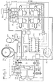
- FIG. 1 schematically shows all of the members making it possible to transmit the hydraulic energy available at the outlet of the heat engine (s) 1, to the front hydraulic motors 3 of the front wheels and to the rear hydraulic motors 3 of the rear wheels.
- One or more heat engines may be available depending on the nature of these and the balancing problems posed.
- FIG. 1 symbolically two motors with a single piston, these motors being opposite to each other.
- Each free piston thermal engine 1 is connected to a hydraulic pump 8, either directly or, as shown, by a hydraulic power transmitter 7, which avoids placing the pump in the axis of the thermal engines and excessively lengthening all.
- the pump 8 delivers high pressure oil via a high pressure line 9 and terminal branches 10, to the hydraulic motors 3, which are connected by low pressure branches 14, giving in a low pressure line 18, to the suction side of the pump 8.
- the hydraulic power transmitter 7 comprises, on the one hand, a transmitter constituted by a cylinder 19 - piston 20 assembly, the piston 20 being mechanically coupled by the rod 20a for example, to the heat piston of the heat engine 1; on the other hand, a receiver constituted by a cylinder 21 - piston 22 assembly, the piston 22 being mechanically coupled by the rod 21a for example, to the pump 8.
- a pipe 23 connects a first chamber of the transmitter to a first chamber of the receiver, and a pipe 24 connects the second chamber of one to the second chamber of the other.
- the chambers and the pipes being filled with low compressible oil, it is clear that the reciprocating movements of the piston 20 of the transmitter are transmitted to the piston 22 of the receiver.
- the pipes 23 and 24 are connected by ball valves 26 and 27 to a line 25 deriving from the low pressure oil reservoir, described below.
- a branch line leads via a three-way solenoid valve 30 to a first high pressure oleopneumatic accumulator 28, used as will be explained below for the acceleration and braking, and a second high pressure accumulator 29, used for cruising speeds.
- the acceleration and braking accumulator 28 intended to supply the energy necessary to go from zero speed to a determined speed ⁇ 1 and to recover this energy, to the nearest yield, during braking from 1 1 to 0, must have a volume of 15 to 25 liters (for a maximum pressure of 330 bars and an inflation pressure of 145 bars), while a volume of 3 to 5 liters (and the same inflation pressure) is sufficient for the cruise accumulator 29, these values corresponding to a 1500 kg vehicle at full load, using standard hydraulic equipment.
- the oleopneumatic accumulators comprise, as shown in more detail for the accumulator 28, a nitrogen chamber 31 separated by an elastomer membrane 32 from the hydraulic fluid chamber 33, constituted by a metal structure 34 on which a kevlar, fiberglass or carbon envelope is wound, according to the known technique of filament winding.
- a 20-liter accumulator with a Kevlar-wound structure weighs at most 25 kg and has greater safety guarantees and heat losses significantly lower than that of a conventional accumulator, which weighs at least 80 kg.
- a low pressure tank 36 is connected to the low pressure pipe 18 and is intended to recover, when the vehicle is at rest, the oil which is found, in operation, in the two accumulators 28 and 29. Taking account of a reserve for leakage, the volume of oil occupying the low pressure tank 36 is 10 liters. The tank is pressurized to avoid cavitation problems in the pump, and the operating pressure (empty tank) being 2 bars and, at rest, 5 bars.
- the hydraulic motors 3 are conventional type variable displacement hydraulic motors.
- the variation of the displacement is obtained for example by the variation of inclination of a plate, the operation of which is carried out on a servo-jack 37. If the variation of inclination is carried out only in one direction (not of negative displacement), then reverse the high and low pressure inputs with a 3-way solenoid valve, to have the reversing device / pump.
- the engine can be used either as an engine during the acceleration and cruising phases, or as a pump during the braking phases. Also the inclination of the plate is connected by means explained later to the vehicle's acceleration and braking pedals.
- FIG. 1 shows four motors, one per wheel: the motors can be identical at the front and at the rear, which offers two combinations of couples; the engines can be more powerful at the front than at the rear, which improves the braking characteristics (which must be greater on the front wheels than on the rear wheels), and offers three combinations of torques.
- a third embodiment instead of providing one motor per wheel, there are, for example, three motors in the center of the vehicle, of different power, which control the wheels of the vehicle by means of a single reducer and a differential; which offers seven combinations of torques, the unused motors being hydraulically and mechanically disconnected.
- the vehicle starts and uses the energy of the accelerating accumulator 28, whose energy-tential p o is transformed into kinetic energy along an isentropic expansion process.
- the pump which with the thermal generator works in all or nothing, starts again as soon as the pressure of the accumulator 28 measured by a sensor 45 is less by a preset value than a given set pressure, and stops as soon as the pressure exceeds by a value preset pressure P c .
- the orders for starting and stopping the heat engine (s) are given by the calculation unit 41 to the injection solenoid valves 2 of the heat engine (s) 1 in response to indications from pressure sensor 45.
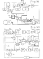
- FIG. 2A is a block diagram of the acceleration operation, where the electrical signals of the variables and the variables are designated by the same symbols, the single lines representing the connections of the electrical signals and the double lines representing the connections of the variables themselves same.
- the pressure P of the acceleration accumulator 28 and the speed V of the vehicle are output variables which are functions of the input variable which is the depressing ⁇ a of the accelerator pedal, transformed by a potentiometric electric transmitter or inductive 48 coupled to the accelerator pedal, in an electrical signal which leaves an amplifier 49 in the form of an electrical output signal still designated by ⁇ a .
- This signal ⁇ a is entered in a controlled amplifier 50 whose return loop 51 has a gain kP proportional to the pressure P.
- the supply of the return loop is done by an electrical signal delivered by the pressure sensor 45 of the accumulator 28.
- the output signal from the servo amplifier 50 corresponds to the setpoint tilt aac of the hydraulic motor plate, and is received by the servo-actuator 37 and transformed into tilt AA of the plate of the motor 3 which is indeed of the form PM P ⁇ a.
- the hydraulic motor 3 under the action of the inclination aa of the plate and of the pressurized fluid P coming from the accumulator 28, delivers a torque which results on the vehicle by a force F a proportional to aaP, it is ie at PM ⁇ a, therefore independent of the pressure P.
- the vehicle is represented at 52 by its transfer function whose input signal is (F - Fr), where Fr is the resistance force due to rolling friction and to the aerodynamic resistance of the vehicle, and whose output signal is the speed ⁇ which is linked to the input signal aa by the following relation:
- the vehicle is not speed controlled because a monostable rocker 70 sensitive to the control voltage uo of the solenoid valve 30 for switching the two accumulators 28 and 29 prevents the speed signal ⁇ from being compared to the signal Sa with the amplifier input 49.
- the acceleration of the vehicle is a linear function of the position of the accelerator pedal, independent of the pressure of the accumulator, the fluctuations of which have been compensated by fluctuations in the opposite direction of the inclination of the plates. thanks to the pressure feedback amplifier 50.
- the hydraulic power is formed of all-or-nothing or pulse duration slots, so that it is the average value W Hm of these slots which is proportional to the difference ⁇ and which is sent to the acceleration accumulator 28.
- the hydraulic motors absorb a power Fose ⁇ 8 ⁇ where Fo is the maximum force developed by the hydraulic motors, the power received by the accumulator 28 is equal to W ⁇ m-Fo ⁇ a ⁇ , which corresponds at pressure P.
- the function generator 54 provides a signal Pc corresponding to economic operation or in overpowered operation.
- the function generator 54 of FIG. 2A comprises four generators of secondary functions, shown in FIG. 2B.
- the function generator 73 from a signal ⁇ - ⁇ c provides a signal which serves as an input signal to the second function generator 74 which delivers a Pco signal.
- the setpoint signal ⁇ c coming from a potentiometric or inductive sensor 77 (maneuvered for example manually by the driver) is transmitted to the first function generator 73 via a monostable rocker of the conventional type 78, symbolized by a contactor where points o and b are joined when ⁇ > ⁇ c .
- the signal ⁇ c is then transmitted to the first function generator 73 and an output signal is then obtained ; the contactor combines the points O and a if the signal ⁇ c is not transmitted.
- the generator 73 then directly transmits the signal ⁇ instead of
- the vehicle is then subjected to a speed proportional to the position of the accelerator pedal and, as in acceleration mode, is insensitive to the jerks of operation of the heat engine.
- Two threshold comparators 79.80 can transmit in parallel, or independently, a voltage u o to the switching solenoid valve 30 of the two accumulators 28 and 29.
- the comparator 79 supplies the voltage u o when the difference ⁇ a - k ⁇ is greater than a value eo close to zerb.
- ⁇ a is equal to k ⁇ , the cruising speed is reached and the solenoid valve 30 is no longer supplied. the accumulator 29 is then switched on.
- the accumulator 28 continues to supply the hydraulic motors until the pressure Pa has dropped to the value Pco corresponding to the speed ⁇ 1 .
- the solenoid valve 30 is then no longer energized and it is the accumulator 29 which takes over to supply the hydraulic motors.
- a second three-way solenoid valve 81 which, at rest, normally supplies the hydraulic motors and the cruise accumulator.
- the solenoid valve 81 is operated on condition of having closed a manual switch 82 which allows the passage of current through the solenoid valve at a voltage ⁇ o.
- This voltage Vo is transmitted under condition by two monostable flip-flops 83,84 placed in series.
- the first 83 authorizes the passage of current to the solenoid valve 81 if the output signal from the amplifier 53 is zero. This null signal corresponds to the period during which the cruise accumulator is being emptied.
- the voltage u of the amplifier reappears and the solenoid valve 81 returns to rest by restoring the hydraulic circuit of the accumulator. cruise.
- the second flip-flop 84 interrupts the flow of current when the acceleration accumulator is full; that is to say when the difference signal between the pressure setpoint signal P cm (maximum) and the pressure sensor signal Pa is zero.
- the hydraulic motors 3 for braking the vehicle. It is known that by reversing the tilt of the plate of a hydraulic motor, the motor torque becomes a braking torque; thus, if the speed ⁇ 1 has been acquired by draining an accumulator, the motor operates during the braking of a speed ⁇ 1 to O in pump and allows the potential energy to be restored to the nearest losses. accumulator.
- the accumulator should be isolated by the solenoid valve 30 and the energy dissipating device 4 used, which gives pressure on the hydraulic motor.
- the device shown diagrammatically in FIG. 1, and detailed in FIG. 3c, creates a pressure drop between the hydraulic motor and the accumulator. It essentially consists of a movable needle 6 actuated by a linear servo-motor 11 and able to create a pressure drop by narrowing the passage section of the hydraulic fluid, the movable needle being placed on the high-pressure line 9, just in upstream of the terminal branches 10, and a pressure relief valve 5, calibrated at the maximum pressure P M and placed between the low pressure pipe 18 and a high pressure pipe point 9, upstream of the needle.
- the solenoid valve 30 isolates the cruise accumulator 29 and puts the acceleration-braking accumulator 28 into communication.
- the pressure of this accumulator being low, the inclination of the plates of the hydraulic motors s 'increases and takes its maximum value as a stop.
- the needle device is controlled as follows.
- the setpoint signal Fc aFc is negative and has an absolute value greater than unity.
- the signal 1 + aFc is applied to the input of an amplifier 90 whose particularity is to provide a proportional voltage under the action of negative signals 1 + aFc and a zero voltage if the signal 1 + aFc is positive.
- the signal u 1 collected is applied to an amplifier 91 whose gain is proportional to the signal from the pressure transmitter 45 of the acceleration accumulator and makes it possible to obtain a signal proportional to (aFc + 1) P which constitutes the signal of setpoint which must be equal to the pressure drop P F -P to maintain a constant torque.
- the pressure P increases in the accumulator and the signal aFc + 1 decreases in absolute value until it is canceled, which also cancels the pressure drop. From 1 + ⁇ Fc ⁇ 0, the braking torque corresponds to the maximum recovery of kinetic energy.
- the operation of the pressure relief valve and the needle corresponds to a dissipation of the hydraulic energy in heat in the fluid. Also to maintain the temperature more or less constant despite the dissipation of the braking energy, it is necessary to convey the hydraulic fluid leaving the pressure relief valve and the needle valve through a convector radiator 94 of a type known for evacuating to the outside the calories from energy dissipation (fig. 3c).
- the different signals that control the vehicle pressure and speed are analog for the function generators and all or nothing for the controls of the fuel injection and hydraulic motor switching solenoid valves. It is advantageous to use the digital calculation technique to calculate the different analog signals or all or nothing using a calculating member 41 comprising a multiplexer, a micropressor and a decoder and which brings together the different electronic elements already seen in the block diagrams and switches them into the pressure and speed currents to have a transmission operation at optimum efficiency. It also has the function of controlling the three-way solenoid valve 30, of controlling the switching 44 of the hydraulic motors, of controlling the injection solenoid valves and of regulating the stroke of the thermal generator by supplying the electrical signals to a servovalve or an electrovalve Fuel injection vernier.
- the computing unit 41 receives in particular at its input 42 the position signals sa of the accelerator pedal; at 15, the position signals af of the brake pedal; at 16, the signals corresponding to the pressure of the acceleration accumulator; in 17, those of the cruise accumulator; at 38, the signals from the speed sensors 57 (for example tachometers); and at 39 signals corresponding to the position af of the plates of the hydraulic motors.
- the output signals from the calculating member 41 are: at 47, the control signal from the solenoid valve 30 of the accumulator circuit; at 40, the control signal from the generator injection solenoid valves; at 59, the control of the additional braking servomotor 11; at 60, the switching signals of the hydraulic motors; in 43 and 61, the setpoint signals for the inclination of the plates of the hydraulic motors for acceleration and braking respectively.
- Pc being the setpoint pressure to be imposed on the acceleration accumulator and aac the setpoint tilt value to be imposed on the engine plate (setpoint displacement).
- the set pressure is such that the motor-pump unit is required to supply an average hydraulic power WHm equal to
- a diesel engine with four in-line cylinders of the conventional type below the plane 105 of the cylinder head gasket is suitable for Aims of the invention by the fact that axial rods 106 are anchored on the upper face of the pistons 101, 102, 103, 104, that is to say on the face opposite the crankshaft, (not shown).
- Each axial rod 106 has a shoulder 107 serving as a hydraulic piston inside a cylinder 108.
- the piston 107 allows the volume V 1 • of the lower chamber 110 of the cylinder 108 to be worked with a single-acting hydraulic pump, the chamber 110 being connected to the hydraulic circuit by a valve box not shown.
- the seal between the axial rod 106 and the pump body 111 is ensured by a minimum clearance in the manufacture of these two parts.
- each axial rod 106 receives, for example by screwing, a driving piston 114, which moves in the chamber 115.
- the driving piston 114 is made of thermal conductive composite material, of the silicon carbide-carbide type. silicon, for example, and has annular grooves 125 for limiting leaks.
- the chamber 115 can be made of a conductive composite material if there is an insulating material not shown outside, or of a thermal insulating composite material, of the silica-silica type for example.
- the set of pistons 114 and the block of chambers 115 constitutes the hot part of the hydraulic generator, the engine block 100 of which is thermally insulated by a flat insulating element 116.
- Exhaust and intake are provided at the lower part of the combustion chamber by lights 119 connected (fig. 4b) to a hot manifold 117, made of conductive composite material or insulating, for the exhaust, and to an intake pipe 118 made of insulating composite material, in order to avoid preheating of the air by conduction between the intake pipe 118 and the chamber 115 of which it is integral.
- crankshaft Being a two-stroke engine with four cylinders with crankshaft, the crankshaft has four crankpins at 90 °, distributes and balances in the four cylinders the phases of the cycle: scanning for the engine piston corresponding to the piston 104, compression for 103 , end of compression for 101, and expansion for 102.
- the intake and exhaust ports are released by the driving piston 114 and there is evacuation of the burnt gases from the previous cycle first naturally then by the purging air.
- crankshaft drives the engine piston 114 towards top dead center until the end of compression.
- injector 122 located at the upper part of the combustion chamber and the opening of which is controlled by the camshaft.
- V I contains high pressure oil, driven to the accumulator as seen above; during the compression stroke, conversely, the volume is filled with low pressure oil from the hydraulic fluid reservoir.
- openings 124 for venting which, like the openings 121 are calibrated and define the cooling air flow necessary to limit the overheating of the engine hydraulic cylinders and especially, by conduction, of the piston rods and pistons 101-104.
- Idle injectors deliver the fuel necessary to overcome losses (friction of the moving body of the "standard engine", thermodynamic losses by lack of adiabaticity, pressure losses cooling air flows, etc.)
- the generator While the vehicle is running, the generator operates at constant speed, which allows, despite the significant inertia in rotation, to instantly go from zero load to nominal load.
- the principle of intermittent operation at power giving optimal performance is thus achieved with a generator connected.
- the generator is started in a conventional manner by the electric starter of the "standard motor” geared to the toothed ring of the flywheel.
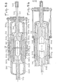
- a two-stroke diesel engine with free pistons has a single effect with a crankshaft sleeve.
- a fixed cylindrical casing 200 In this generator of plane of symmetry P, a fixed cylindrical casing 200, made of metal and little stressed both mechanically and thermally, contains a fur 201, two movable liners 202a and 202b and two pistons 203a and 203b.
- the fixed fur 201 made of insulating composite material, extends over only part of the length of the bore of the casing 200 on either side of the plane of symmetry P of the generator.
- the two liners 202a and 202b at all times symmetrical with respect to the plane P, by virtue of a synchronization device, an example of which is described below, are made of possibly conductive composite material. They are extended by a hollow rod 204 which crosses the casing 200 on the axis of symmetry 205 of the generator.
- the two pistons 203a and 203b are extended by a rod 206 which slides inside the sleeve rod 204 and drives the pump piston hydraulic receiver (207).
- connecting rods 208a and 209a, the head of which is secured to the liner 202a by a connection 210 screwed onto the hollow rod 204 protruding outside the casing; and 208b and 209b secured to the jacket 202b by an identical connection, not shown.
- An injector 213 allows each cycle to introduce a metered quantity of fuel into the combustion chamber situated around the point of symmetry of the generator thus described and delimited by the opposite faces of one liner-piston assembly and the other.
- the fuel is injected a few moments before the jackets 202a and 202b come into their closest position (fig. 5a), by the injector 213 triggered from one of the pinions 211 or 212 ,.
- the liners 202a and 202b have identical and very much stronger masses than those of the pistons 203a and 203b, so that the pistons have a stronger initial acceleration than the liners.
- the acceleration of the latter changes sign and they come, on their kinetic energy, to come to a stop in the position represented by FIG. 5b.
- the liners 202a and 202b continue their course beyond the piston while compressing air in the volumes 214a and 214b situated between the front external face of the liners and the internal face of the casing. This air mattress is intended to accumulate the energy necessary for compression for the next cycle.
- this air mattress can correspond to a larger bore than that of the jacket on the combustion chamber side, which makes it possible to limit the pressure at the end of compression and correspondingly the temperature and the working rate of the crankcase.
- This bore depends in part on the mass ratio between pistons and liners that one seeks to achieve.
- Orifices 215 of venting air from the outer annular volume of the liner are provided in the housing wall 200 at the edge of the fur 201 wherein slide shirts 2 0 2. These holes can be used to complete a capacitor. air for sweeping the engine.
- each liner releases diametrically opposite orifices: 216a and 216b for the exhaust of the burnt gases, and 217a and 217b for the admission of fresh air. Due to the asymmetrical position of said orifices 216 and 217, a very efficient sweeping occurs, which is very important in a two-stroke engine.
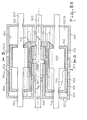
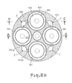
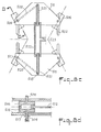
- a third embodiment of the free piston generator in accordance with the invention, consists of a two-stroke diesel generator with double-acting free pistons, shown in FIGS. 6a, 6b, 6c.
- a fixed casing 300 made of insulating composite material, has four bores ' 301 distributed symmetrically around its axis 302, in which slide four sleeves 303 made of conductive composite material, advantageously coated with insulating composite material on their external front and rear faces, 304 and 305.
- pistons 306 slide inside the liners 303 and have axial rods 307 on either side connecting them to the pistons of the hydraulic pumps receiving the power developed by the movement of the engine pistons (not shown).
- a screw 308 made of self-lubricating carbon-carbon type composite material and disposed on the axis of symmetry 302 of the engine, ensures, by opposite threads located on either side of a central shoulder 309 free to rotate in the fixed casing but immobilized in translation, a rigorously symmetrical movement of the two groups of two diametrically opposite sleeves.
- said liners are connected two by two by connecting elements 310 (respectively 311) tapped on the axis of symmetry of the generator to receive the screw 308.
- the pistons 306 and their liners 303 are provided with multiple respective external grooves 315 and 316 intended to limit the flow rates of leakage and in any case to oppose that, in the time of a outward or return stroke, the leakage does not can reach the opposite side of the piston or jacket.
- two grooves 318 intended for air transfers taking place: on the one hand, at the intake, between the casing 300 and the outside of the shirts 303; and, on the other hand, during the scanning of the cylinder (dotted arrow 319, fig. 6a) at the end of the rebound stroke, by intercommunication between the outside and inside of the liners.
- a single groove 318 can be used successively for the two functions mentioned above.
- the grooves 318 can have three ribs in the axial direction, in order to maintain the centering effect in the bore of the casing or of the jacket.
- radial orifices 320 are arranged which are alternately opposite radial orifices 321a and 321b produced in the fixed casing 300.
- the gases burned first then a fraction of the sweeping air is discharged through the orifices.
- the orifices 320, 321a and 321b, not all shown, are in even numbers and diametrically opposite two by two for each of the four mobile assemblies.
- the generator is started either mechanically, for example by means of an electric starter driving the screw 308 in alternating rotation, or pneumatically, by a reserve of pressurized air supplying alternately the front 322a and rear 322b volumes of the liners 303, or hydraulically, by operating the hydraulic pumps associated with the pistons 306 as a starting motor.
- the piston 306 is subjected to a greater acceleration than the jacket (heavier than the piston) but very quickly this acceleration is canceled out and is reversed due to the hydraulic force antagonizing the expansion of the gases on the piston.
- the piston then comes to its left stop. It is a very classic hydraulic stop which it is unnecessary to describe.
- the shirt 303 continues to run to the right under the effect of its own speed and the end of detection energy. However, the acceleration is canceled out and reversed under the combined effect and compression on the left face of the piston 306, and compression of the sweeping air of the volume 322b on the external right face of the liner 303.
- the volume 322b between liner and casing 300 was in fact closed by the displacement of the piston 306 which has shifted the groove 318 to the left, thereby closing the annular clearance between the piston pin and the corresponding bore in the casing 300.
- the bore of the right face of the jacket which slides on the piston rod 307 arrives opposite the groove 318 formed on said rod 307 and allows the admission of the sweeping air previously subjected to a slight compression in the volume 322b between the right face of the jacket 303 and the casing 300.
- the assembly of four identical cylinders in the same generator ensures the diametrical symmetry, necessary not to exert bending torque on the synchronization screw 308, and the overall balancing by a simultaneous but opposite movement of two pairs of shirts . It should be understood that instead of four cylinders, one can have any number n of cylinders, n however being even and greater than four t in this case there will be n combustion chambers and n injectors.
- a hydraulic stop system (figure 7) is added to the generator. It is constituted by a piston 400 mechanically integral with the pump 401 associated with the generator 402.
- the piston 400 moves in a cylinder 403 drilled laterally in the vicinity of its ends of two orifices 404 and 405 joined to the low-pressure tank via two non-return ball valves 406 and 407.
- the piston 400 When the piston 400 reaches the end of its travel, it masks one of the two orifices and compresses the volume of fluid between the orifice and the face of the cylinder, which achieves the stop elastic.
- the reduction in stroke is combated by a device comprising two potentiometric or inductive sensors, placed at each end of the pump cylinders, or of generators, or of the hydraulic stop cylinder, and delivering signals which, after treatment, are transmitted to an auxiliary fuel injection solenoid valve.
- the pump associated with the generator and delivering in the high accumulator pressure which fills with increasing pressure can be a linear pump (piston sliding in a cylinder) provided with a "rectification circuit" making it possible to direct the flow always in the same direction.
- This rectification device can be constituted, for example, by a set of balls arranged between the pump and the high and low pressure circuits to which it is connected.
- the stroke and the force on the piston are constant, whatever the pressure in the accumulator.
- the flow rate (or displacement) varies in inverse ratio to the pressure.
- the pump should therefore be a pump with constant hydraulic power, whatever the level of the discharge pressure.
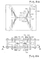
- Figures 8a, 8b, 8c, 8d show an embodiment of a double-acting constant power pump.
- Two parallel flanges 500 and 501 are pierced by four vertical lights 502 and four oblique lights 503 which serve as slides for the two axes respective supports 504 and 505 of each of four single-acting pump bodies 506, placed between the two flanges.
- the oblique lights 503 are inclined at an angle between 20 ° and 64 °, for operation of the pump at a pressure varying between 140 and 300 bars.
- the right pump bodies are subject to move symmetrically relative to the axis of movement 507 while remaining oriented and returned to a fixed point 508 (fig. 8a) by springs 509 (fig. 8b) attached on one side to the support axes 505 sliding in the oblique slides 503, and on the other to a fixed axis 510 passing through the fixed point 508.
- the rods 512 of the pistons of the pumps 506 are mechanically associated by an articulation 513 with a end 514 of the piston rod of the hydraulic receiver 515 of the power transmitter.
- a similar arrangement prevails for the left-hand pump bodies, the rods of which are connected to the other end 516 of the piston rod of the receiver 515.
- the pistons of the hydraulic receiver 515 communicate their movements to the set of four pumps 506, which are connected to the high and low pressure hydraulic circuit as shown in FIGS. 8c and 8d.
- Each pump cylinder 506 is supplied with fluid via a path 516 in the thickness of the cylinder, a path which opens out through a bore 517 in the axis 504 which passes through the vertical slide 502.
- the fluid continues its path through a passage 520 inside the movable plates 511, by means of rotary joints 528 and 519.
- the two movable plates 511 shown in the foreground of FIG. 8c serve as a path for the fluid concerned by the left cylinders, while the movable flanges in the background serve for a path for the fluid concerned by the right cylinders.
- a hole 523 in the cylinder 522 is used for connection to the valve box and, from there, for the high and low pressure hydraulic circuit.
Landscapes
- Engineering & Computer Science (AREA)
- Chemical & Material Sciences (AREA)
- Combustion & Propulsion (AREA)
- Mechanical Engineering (AREA)
- Transportation (AREA)
- General Engineering & Computer Science (AREA)
- Arrangement Or Mounting Of Propulsion Units For Vehicles (AREA)
- Control Of Fluid Gearings (AREA)
Applications Claiming Priority (2)
| Application Number | Priority Date | Filing Date | Title |
|---|---|---|---|
| FR8015416A FR2486464A1 (fr) | 1980-07-10 | 1980-07-10 | Procede de propulsion d'un vehicule a roue(s) et vehicule mettant en oeuvre ledit procede |
| FR8015416 | 1980-07-10 |
Publications (1)
| Publication Number | Publication Date |
|---|---|
| EP0044252A1 true EP0044252A1 (fr) | 1982-01-20 |
Family
ID=9244086
Family Applications (1)
| Application Number | Title | Priority Date | Filing Date |
|---|---|---|---|
| EP81401109A Ceased EP0044252A1 (fr) | 1980-07-10 | 1981-07-09 | Procédé et systeme de propulsion d'un véhicule à roues à transmission hydraulique |
Country Status (2)
| Country | Link |
|---|---|
| EP (1) | EP0044252A1 (Direct) |
| FR (1) | FR2486464A1 (Direct) |
Cited By (8)
| Publication number | Priority date | Publication date | Assignee | Title |
|---|---|---|---|---|
| FR2629171A1 (fr) * | 1988-03-25 | 1989-09-29 | Moiroux Auguste | Dispositif de transmission hydrostatique et application a un groupe motopropulseur ou un vehicule automobile |
| DE4023506A1 (de) * | 1990-07-24 | 1992-02-06 | Gerhard Brandl | Hydraulischer hybridantrieb fuer kraftfahrzeuge |
| EP0734495A4 (en) * | 1994-10-13 | 1998-10-28 | Nigel Eric Rose | HYDRAULIC MOTORS AND MOTOR MECHANISMS |
| WO2008012006A3 (de) * | 2006-07-22 | 2008-12-18 | Franz Brauers | Hubkolben-verbrennungskraftmaschinen |
| FR3028568A1 (fr) * | 2014-11-18 | 2016-05-20 | Poclain Hydraulics Ind | Accumulateur avec piston relais |
| CN110273864A (zh) * | 2018-03-16 | 2019-09-24 | A&A国际有限公司 | 热液压引力能量转换系统 |
| CN113163716A (zh) * | 2018-09-27 | 2021-07-23 | 海乐有限责任公司 | 液压动力的打捆机 |
| CN113942381A (zh) * | 2021-09-15 | 2022-01-18 | 浙江大学 | 基于工况模式的液压混合动力轮式装载机能量优化方法 |
Families Citing this family (4)
| Publication number | Priority date | Publication date | Assignee | Title |
|---|---|---|---|---|
| CN114810539B (zh) * | 2021-01-29 | 2025-07-25 | 上海强田驱动技术有限公司 | 功率分流电液混合动力总成 |
| CN114810540B (zh) * | 2021-01-29 | 2025-07-25 | 上海强田驱动技术有限公司 | 低速大扭矩无级变速电液驱动系统 |
| CN114810538B (zh) * | 2021-01-29 | 2025-07-25 | 上海强田驱动技术有限公司 | 大功率低速大扭矩电液驱动系统 |
| CN115324753B (zh) * | 2022-09-23 | 2024-03-19 | 湖南道依茨动力有限公司 | 发动机转速预控制方法、系统、发动机及作业设备 |
Citations (3)
| Publication number | Priority date | Publication date | Assignee | Title |
|---|---|---|---|---|
| FR2257014A1 (en) * | 1974-01-07 | 1975-08-01 | Sigaud Pierre | IC engine with hydraulic transmission - has hydropneumatic accumulators on low and high pressure circuits |
| FR2306384A1 (fr) * | 1975-03-30 | 1976-10-29 | Technion Res & Dev Foundation | Dispositif de transmission hydrostatique |
| GB2019537A (en) * | 1978-04-20 | 1979-10-31 | Ricecerche Fiat Spa Centro | Hydraulic transmission for motor vehicle |
-
1980
- 1980-07-10 FR FR8015416A patent/FR2486464A1/fr active Granted
-
1981
- 1981-07-09 EP EP81401109A patent/EP0044252A1/fr not_active Ceased
Patent Citations (3)
| Publication number | Priority date | Publication date | Assignee | Title |
|---|---|---|---|---|
| FR2257014A1 (en) * | 1974-01-07 | 1975-08-01 | Sigaud Pierre | IC engine with hydraulic transmission - has hydropneumatic accumulators on low and high pressure circuits |
| FR2306384A1 (fr) * | 1975-03-30 | 1976-10-29 | Technion Res & Dev Foundation | Dispositif de transmission hydrostatique |
| GB2019537A (en) * | 1978-04-20 | 1979-10-31 | Ricecerche Fiat Spa Centro | Hydraulic transmission for motor vehicle |
Cited By (10)
| Publication number | Priority date | Publication date | Assignee | Title |
|---|---|---|---|---|
| FR2629171A1 (fr) * | 1988-03-25 | 1989-09-29 | Moiroux Auguste | Dispositif de transmission hydrostatique et application a un groupe motopropulseur ou un vehicule automobile |
| WO1989009144A1 (fr) * | 1988-03-25 | 1989-10-05 | Auguste Moiroux | Groupe motopropulseur, notamment pour vehicule automobile et vehicule comportant un tel groupe |
| DE4023506A1 (de) * | 1990-07-24 | 1992-02-06 | Gerhard Brandl | Hydraulischer hybridantrieb fuer kraftfahrzeuge |
| WO1992001584A1 (de) * | 1990-07-24 | 1992-02-06 | Gerhard Brandl | Hydraulischer hybridantrieb für kraftfahrzeuge |
| EP0734495A4 (en) * | 1994-10-13 | 1998-10-28 | Nigel Eric Rose | HYDRAULIC MOTORS AND MOTOR MECHANISMS |
| WO2008012006A3 (de) * | 2006-07-22 | 2008-12-18 | Franz Brauers | Hubkolben-verbrennungskraftmaschinen |
| FR3028568A1 (fr) * | 2014-11-18 | 2016-05-20 | Poclain Hydraulics Ind | Accumulateur avec piston relais |
| CN110273864A (zh) * | 2018-03-16 | 2019-09-24 | A&A国际有限公司 | 热液压引力能量转换系统 |
| CN113163716A (zh) * | 2018-09-27 | 2021-07-23 | 海乐有限责任公司 | 液压动力的打捆机 |
| CN113942381A (zh) * | 2021-09-15 | 2022-01-18 | 浙江大学 | 基于工况模式的液压混合动力轮式装载机能量优化方法 |
Also Published As
| Publication number | Publication date |
|---|---|
| FR2486464A1 (fr) | 1982-01-15 |
| FR2486464B1 (Direct) | 1984-11-09 |
Similar Documents
| Publication | Publication Date | Title |
|---|---|---|
| FR3001776A1 (fr) | Palier de rotor pour moteur-pompe | |
| EP0044252A1 (fr) | Procédé et systeme de propulsion d'un véhicule à roues à transmission hydraulique | |
| CA1325578C (fr) | Groupe motopropulseur a accumulateur elastique d'elasticite variable et vehicule comportant un tel groupe | |
| FR2491133A1 (fr) | Moteur de vehicule a cylindres disposes en ligne | |
| FR2528515A1 (fr) | Procede d'entrainement de vehicules automobiles comportant un volant d'inertie avec differentiel et un systeme d'entrainement mettant en oeuvre le procede | |
| FR2476231A1 (fr) | Systeme de commande hydraulique du mecanisme d'entrainement d'un demarreur d'aeronef | |
| FR2830065A1 (fr) | Boite de vitesses a fonctionnement continu du type a disposi tif d'entrainement a bielles et excentrique | |
| FR2520827A1 (fr) | Transmission a division de puissance concue pour fonctionner en traction pure, en recuperation-restitution de l'energie cinetique, et en mode hybride | |
| EP0026115B1 (fr) | Transmissions hydrostatiques de puissance à grande plage de fonctionnement | |
| FR2801086A1 (fr) | Systeme d'entrainement pour chariot de manutention | |
| FR2468799A1 (fr) | Transmission hydromecanique comportant eventuellement un coupleur hydrocinetique d'appoint en particulier pour direction de vehicules chenilles | |
| EP2066922A2 (fr) | Dispositif de transformation d'un mouvement linéaire en un mouvement de rotation de façon réglable | |
| WO2015189324A1 (fr) | Procede d'activation d'une assistance hydraulique d'un systeme de transmission de vehicule | |
| FR2614961A1 (fr) | Transmission dissipative a gammes multiples et rapport variable en continu | |
| EP0013190B2 (fr) | Groupe propulseur hydraulique pour véhicule à recyclage mécanique de puissance en virage | |
| EP0025372B1 (fr) | Groupe propulseur à transmissions hydrostatiques assurant la translation et la direction avec recyclage hydraulique de puissance en virage | |
| EP0359654A1 (fr) | Transmission pour véhicules chenillés rapides ou à roues non directrices | |
| FR3116798A1 (fr) | Ensemble de transmission pour engin de mobilité et procédé | |
| EP0009758A1 (fr) | Dispositif de commande d'une transmission automatique et procédé de mise en oeuvre | |
| EP1167720B1 (fr) | Moteur à phase isochore | |
| WO2014174167A1 (fr) | Chaine de traction pour un vehicule hybride hydraulique, procédé de commande et véhicule automobile hybride | |
| FR2895941A1 (fr) | Dispositif de propulsion bimoteur pour un vehicule de fortes performances, de faibles consommation et de faibles emissions polluantes | |
| WO1992012042A1 (fr) | Bicyclette a transmission hydrostatique | |
| FR2717225A1 (fr) | Procédé et ensemble de suralimentation pour moteurs à deux temps et applications. | |
| EP0544580A1 (fr) | Centrifugeuse à moteurs hydrauliques, notamment pour l'entraînement de pilotes d'aéronefs |
Legal Events
| Date | Code | Title | Description |
|---|---|---|---|
| PUAI | Public reference made under article 153(3) epc to a published international application that has entered the european phase |
Free format text: ORIGINAL CODE: 0009012 |
|
| AK | Designated contracting states |
Designated state(s): DE FR GB IT NL SE |
|
| 17P | Request for examination filed |
Effective date: 19820615 |
|
| STAA | Information on the status of an ep patent application or granted ep patent |
Free format text: STATUS: THE APPLICATION HAS BEEN REFUSED |
|
| 18R | Application refused |
Effective date: 19841102 |