EP0044251B1 - Dispositif pyrotechnique de découpage et d'éjection d'un élément transparent de verrière d'avion - Google Patents
Dispositif pyrotechnique de découpage et d'éjection d'un élément transparent de verrière d'avion Download PDFInfo
- Publication number
- EP0044251B1 EP0044251B1 EP19810401103 EP81401103A EP0044251B1 EP 0044251 B1 EP0044251 B1 EP 0044251B1 EP 19810401103 EP19810401103 EP 19810401103 EP 81401103 A EP81401103 A EP 81401103A EP 0044251 B1 EP0044251 B1 EP 0044251B1
- Authority
- EP
- European Patent Office
- Prior art keywords
- transparent element
- canopy
- detonating cord
- cord
- groove
- Prior art date
- Legal status (The legal status is an assumption and is not a legal conclusion. Google has not performed a legal analysis and makes no representation as to the accuracy of the status listed.)
- Expired
Links
- 238000005474 detonation Methods 0.000 claims description 14
- 239000011324 bead Substances 0.000 claims 3
- 230000003014 reinforcing effect Effects 0.000 claims 1
- 238000000926 separation method Methods 0.000 claims 1
- 239000002131 composite material Substances 0.000 description 3
- 230000000694 effects Effects 0.000 description 3
- 239000011521 glass Substances 0.000 description 3
- 238000004026 adhesive bonding Methods 0.000 description 2
- 230000000295 complement effect Effects 0.000 description 2
- 238000005516 engineering process Methods 0.000 description 2
- 230000001939 inductive effect Effects 0.000 description 2
- 230000014759 maintenance of location Effects 0.000 description 2
- 239000000463 material Substances 0.000 description 2
- 238000000034 method Methods 0.000 description 2
- 230000002787 reinforcement Effects 0.000 description 2
- 230000003313 weakening effect Effects 0.000 description 2
- 230000005540 biological transmission Effects 0.000 description 1
- 230000001413 cellular effect Effects 0.000 description 1
- 230000002508 compound effect Effects 0.000 description 1
- 230000032798 delamination Effects 0.000 description 1
- 230000009429 distress Effects 0.000 description 1
- 238000013467 fragmentation Methods 0.000 description 1
- 238000006062 fragmentation reaction Methods 0.000 description 1
- 239000007789 gas Substances 0.000 description 1
- 238000009434 installation Methods 0.000 description 1
- 230000000149 penetrating effect Effects 0.000 description 1
Images
Classifications
-
- B—PERFORMING OPERATIONS; TRANSPORTING
- B64—AIRCRAFT; AVIATION; COSMONAUTICS
- B64C—AEROPLANES; HELICOPTERS
- B64C1/00—Fuselages; Constructional features common to fuselages, wings, stabilising surfaces or the like
- B64C1/32—Severable or jettisonable parts of fuselage facilitating emergency escape
Definitions
- the present invention relates to a pyrotechnic device allowing both the cutting and the ejection of a transparent element of aircraft canopy so as to facilitate the emergency evacuation of the crew.
- devices have many advantages compared to conventional devices (mechanical, pneumatic, electrical, etc.). In particular, they offer the possibility of cutting any type of material and they present a speed of operation (a few milliseconds), a high power (several hundred kilobars), a high reliability and a mass balance lower than the mass balance of all other system.
- the objective to be achieved is to obtain the evacuation of a member of the crew as quickly as possible thanks to its ejectable seat, the trajectory of which must be clear of any obstacle and in particular of the canopy of the passenger compartment.
- a pyrotechnic device integrated into the structure of the canopy of an aircraft ensuring the cutting and the ejection of the transparent element of said canopy, by means of a detonating cord, has at the periphery of the canopy so as to facilitate the ejection of the crew out of the cockpit provided with ejectable seats, said canopy being held in the structure of the cockpit by two longitudinal edges comprising a profile d 'hanging of the transparent element on said canopy and two arches comprising a heel for hanging said element.
- the present invention relates to a pyrotechnic device of the last type, characterized in that the detonating cord is housed, on the one hand in a first groove formed in the longitudinal edges, against the attachment profile and below the underside of the edge of the transparent element, and on the other hand in a second groove formed in the front and rear arches, facing and against the hooking heel.
- the pyrotechnic device makes it possible to cut and eject the transparent element from the canopy of an airplane, this transparent element being detached and ejected from the airplane, along the longitudinal edges, using the energy supplied by the detonation of the pyrotechnic cord, placed under the edges of the transparent element, so as to cut the attachment profile of said element on the longitudinal edges of the canopy and to create a strong pressure at its base giving it a maximum impulse directed vertically from the bottom up, and along the front and rear arches, using the energy supplied by the detonation of the pyrotechnic cord, placed against the heel of the transparent element, so that at the level of the bow before it causes a frank cut of the heel and the transparent element by inducing a complementary impulse from the inside to the outside of the cabin, and that at the rear arch, it causes the cut age of the heel and of the transparent element by inducing a limited complementary pulse resulting in a temporary retention of the transparent element on the heel, the combined action of these take-off, of these cut-outs and of
- the cutting of the transparent element of the canopy is carried out by making a portion of the attachment profile remain at the periphery of said element ensuring better mechanical resistance and avoiding its fragmentation.
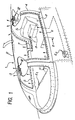
- a canopy 1 of an airplane comprising a transparent element 2 held in a front hoop 3, a rear hoop 4 and two longitudinal edges 5 and 6, also allowing the transparent element to be held on the canopy .
- the latter is articulated laterally on hinges such as 7 and its opening is effected by lateral tilting. It could be articulated differently and tilt from front to back.
- the device according to the invention could also be applied to a sliding canopy.
- Such a canopy allows access to the passenger compartment of the aircraft and its normal evacuation to the ground.
- a detonating cord 8, placed at the periphery of the canopy is housed in the longitudinal edges 5 and 6 and in the arches 3 and 4; its positioning will be described in more detail later. It is connected to the detonation means, not shown, by a transmission chain such as 9.
- This pyrotechnic device cuts and ejects the transparent element 2 so as to facilitate the emergency evacuation of the crew from the passenger compartment of the aircraft.
- the detonation of the pyrotechnic cord 8 is generally controlled by the seat movement 5 or any start of its ejection phase by any known means.
- the detonation of the pyrotechnic cord 8 can be accomplished, independently of the ejectable seat S, by manual control.
- This can include an interior trigger handle E l and at least one exterior trigger handle E 2 , allowing the cutting of the transparent element and its ejection, without intervention of the ejectable seat, and being able to be actuated either by a member of the crew, or by any outside party.
- FIG 2 there is shown a section along It of the longitudinal border 5 of Figure 1, the border 6 being identical to the latter.
- This longitudinal edge 5 comprises a housing 10 intended to receive the edge of the transparent element 2 by means of a rod fastening profile 11 of known type, made of composite material.
- This profile 11 has two vertical walls such as 12 to which the transparent element adheres by gluing, walls which join at 13 by enclosing the rod 14.
- the inclined walls such as 15 which are the extension of the walls 12 of the attachment profile delimit with the lower face 2 ′ of the edge of the transparent element 2 a space filled with a filling material of the cellular type or the like.
- the detonating cord 8 is disposed in a groove 16 formed in one face of the cavity forming the housing 10, belonging to the internal part of the longitudinal edge 5.
- the opening 16 'of said groove is located opposite the inclined wall 15 and turned towards the interior of the passenger compartment while in the same zone, containing the cord, and in order to reinforce it, the longitudinal edge 5 offers a bulge such as 17.
- Such an arrangement of the cord 8 has the first effect, when from its detonation, to cut the profile 11 at the location of the walls 15 while the second effect, due to the instantaneous high pressure of the gases, induces a maximum vertical impulse said from bottom to top according to the arrow F 1 which takes off the walls profile 11 of their housing 10 and ejects the transparent element above the passenger compartment.
- FIG. 3 represents a section along plane III of the front arch 3 of FIG. 1.
- This arch consists of two structural elements: an internal element 18 and an external element or joint cover 19. These two elements sandwich a heel attachment 20 made of composite material offering a housing 20 'with two walls, an internal wall 21 and an external wall 22, intended to receive the transparent element 2.
- the internal wall 21 exceeds the bulged end forming reinforcement 23 of the internal structural element 18 of the arch and is applied to the transparent element over a greater width than the external wall 22 of said housing.
- the transparent element 2 is made integral with its hooking heel 20 by gluing and the assembly of the assembly is carried out by bolting such as 24.
- a groove 25 is formed in the internal face of the element 18, in line with its part of reinforcement 23, a groove 25 is formed.
- An opening 25 ′ of said groove is located opposite the internal wall 21 and substantially opposite the end of the external wall 22.
- the pyrotechnic cord 8 one of which first length is installed in the longitudinal border 5.
- This positioning of the cord 8 added to the shape of the hooking heel 20 of the transparent element 2 is such that the detonation of the cord causes a sharp cutting of said element and a significant impulse led from in outside towards the outside of the passenger compartment as indicated by arrow F 2 .
- the detonating cord 8 housed as we have seen in the longitudinal border 5, then in the front arch 3, is then placed in the border 6 in the same way as in the border 5.
- the installation of the continuation of the cord 8 in the rear hoop 4, a section along IV of Figure 1 is shown in Figure 4, is carried out as shown below.
- the rear hoop 4 is composed of two structural elements, namely an internal element 26 and an external element or joint cover 27. These two elements sandwich a hooking heel 28 made of composite material offering a housing 28 'for two walls, an internal wall 29 and an external wall 30, intended to receive the transparent element 2.
- the internal wall 29 covers the latter over a width less than the width of the external wall 30.
- the transparent element 2 is made integral with its attachment heel 28 by bonding and the assembly of the assembly is carried out by bolting 31.
- a groove 33 is formed in the internal face of the element 26, in the reinforced zone 32.
- the opening 33 ′ of said groove is located opposite the wall 29 and also opposite the external wall 30.
- In the groove 33 is disposed the detonating cord 8.
- the positioning of the latter and the shape of the hooking heel 28 are such that the detonation of the cord causes partial rupture of the transparent element 2 followed by delamination of its edge contributing to a temporary retaining effect on the pulse directed from the interior to the exterior of the passenger compartment as indicated by arrow F 3 .
- the pyrotechnic device and the method for ejecting the transparent element from the canopy can be adapted to any type of single or multi-seater airplane canopy.
- the canopy is composed of two transparent elements, front and rear, these are separated by a single central arch, the technology of which will be that shown in FIG. 3 for the rear part of the arch. and that which is represented in FIG. 4 for the front part.
- a glass roof made up of two transparent elements, left and right these are separated by a longitudinal central upright, the technology of which will be identical to that which is shown in FIG. 2.
- the pyrotechnic cutting chains can be separated and their detonation can be either separate or simultaneous.
Landscapes
- Engineering & Computer Science (AREA)
- Mechanical Engineering (AREA)
- Aviation & Aerospace Engineering (AREA)
- Body Structure For Vehicles (AREA)
- Air Bags (AREA)
Applications Claiming Priority (2)
| Application Number | Priority Date | Filing Date | Title |
|---|---|---|---|
| FR8015489 | 1980-07-11 | ||
| FR8015489A FR2486489A1 (fr) | 1980-07-11 | 1980-07-11 | Dispositif et procede pyrotechniques de decoupage et d'ejection d'un element transparent de verriere d'avion |
Publications (2)
| Publication Number | Publication Date |
|---|---|
| EP0044251A1 EP0044251A1 (fr) | 1982-01-20 |
| EP0044251B1 true EP0044251B1 (fr) | 1985-01-02 |
Family
ID=9244114
Family Applications (1)
| Application Number | Title | Priority Date | Filing Date |
|---|---|---|---|
| EP19810401103 Expired EP0044251B1 (fr) | 1980-07-11 | 1981-07-08 | Dispositif pyrotechnique de découpage et d'éjection d'un élément transparent de verrière d'avion |
Country Status (3)
| Country | Link |
|---|---|
| EP (1) | EP0044251B1 (OSRAM) |
| DE (1) | DE3168029D1 (OSRAM) |
| FR (1) | FR2486489A1 (OSRAM) |
Families Citing this family (5)
| Publication number | Priority date | Publication date | Assignee | Title |
|---|---|---|---|---|
| FR2542697B1 (fr) * | 1983-03-14 | 1986-03-21 | Dassault Avions | Procede et dispositif pyrotechnique d'ejection hors d'un avion |
| FR2559451B1 (fr) * | 1984-02-09 | 1986-08-08 | Dassault Avions | Dispositif de connexion pour circuit pyrotechnique aboutissant a une verriere d'avion |
| FR2619738B1 (fr) * | 1987-08-31 | 1993-12-17 | Dassault Breguet Aviation | Procede pour creer une separation dans une piece a l'aide d'un tube expansible pyrotechnique |
| AU7782601A (en) * | 2000-08-08 | 2002-03-22 | Yusupovich Khalidov Hamid | Aparc system for air passengers and load rescue |
| DE10112413C2 (de) * | 2001-03-15 | 2003-04-10 | Eurocopter Deutschland | Notausstiegsluke für einen flugfähigen Flugzeugprototyp |
Family Cites Families (4)
| Publication number | Priority date | Publication date | Assignee | Title |
|---|---|---|---|---|
| US3486410A (en) * | 1968-04-18 | 1969-12-30 | Mc Donnell Douglas Corp | Explosive severance means |
| FR2077846A1 (OSRAM) * | 1970-02-18 | 1971-11-05 | Dassault Aeronautique | |
| GB1383511A (en) * | 1971-01-15 | 1974-02-12 | Hawker Siddeley Aviation Ltd | Aircraft canopy emergency |
| US3919939A (en) * | 1974-11-01 | 1975-11-18 | Us Navy | Method and means for flash suppression |
-
1980
- 1980-07-11 FR FR8015489A patent/FR2486489A1/fr active Granted
-
1981
- 1981-07-08 DE DE8181401103T patent/DE3168029D1/de not_active Expired
- 1981-07-08 EP EP19810401103 patent/EP0044251B1/fr not_active Expired
Also Published As
| Publication number | Publication date |
|---|---|
| DE3168029D1 (en) | 1985-02-14 |
| FR2486489B1 (OSRAM) | 1982-10-29 |
| FR2486489A1 (fr) | 1982-01-15 |
| EP0044251A1 (fr) | 1982-01-20 |
Similar Documents
| Publication | Publication Date | Title |
|---|---|---|
| EP2733066B1 (fr) | Procédé de déclenchement automatique d'un système de flottabilité de secours pour hélicoptère hybride | |
| FR2634171A1 (fr) | Systeme pyrotechnique pour pratiquer une issue de secours dans une paroi d'un aeronef et aeronef equipe dudit systeme | |
| EP1209077B1 (fr) | Dispositif d'accès a bord pour aéronef et aile volante équipée d'un tel dispositif | |
| FR2478572A1 (fr) | Installation de securite pour avions | |
| EP2064114B1 (fr) | Systeme de verrouillage et de deverrouillage d'une porte de cockpit d'un aeronef et porte comportant un tel systeme | |
| EP2586705B1 (fr) | Aéronef muni d'un système de flottabilité d'un élément tournant | |
| EP0013529B1 (fr) | Glace munie d'un dispositif de découpage pyrotechnique | |
| FR2766156A1 (fr) | Encadrement de vitre permettant le largage d'un hublot d'helicoptere | |
| EP0020226B1 (fr) | Dispositif de transport et de largage d'une pluralité de charges contenues dans un conteneur | |
| EP0044251B1 (fr) | Dispositif pyrotechnique de découpage et d'éjection d'un élément transparent de verrière d'avion | |
| EP2735506B1 (fr) | Procédé d'agencement d'un système de flottabilité sur un aéronef, système de flottabilité pour aéronef, et aéronef | |
| FR2772340A1 (fr) | Parachutes de secours pour helicoptere | |
| FR2542697A1 (fr) | Procede et dispositif pyrotechnique d'ejection hors d'un avion | |
| EP2743175A1 (fr) | Fond étanche avant d'aéronef comprenant des renfoncements pour le logement d'équipements de cockpit | |
| EP3409585B1 (fr) | Aeronef muni d'un systeme de flottabilite, et procede de flottabilite | |
| FR3031316A1 (fr) | Dispositif de production d'oxygene au moyen d'une reaction chimique a deux cœurs de reaction chimique | |
| EP1902757B1 (fr) | Dispositif de propulsion d'un agent contenu dans une cavité | |
| EP0225247B1 (fr) | Voilure de parachute | |
| EP3459853A1 (fr) | Dispositif de securite conçu pour equiper une sellette de parapente ou d'aeronef, et sellette equipee d'un tel dispositif | |
| EP3476718B1 (fr) | Hublot largable de vehicule et vehicule comprenant un tel hublot | |
| EP0363543B1 (fr) | Mécanisme d'accrochage d'un dispositif de sauvetage du type toboggan simple ou canot pour aéronef | |
| FR2524858A1 (fr) | Agencement de dispositifs pour sectionner et enlever des parties de paroi du toit de cabine de postes de pilotage | |
| WO2019202257A2 (fr) | Système pour le lancement d'une aile de parapente depuis la stratosphère | |
| FR2687124A1 (fr) | Systeme automatique d'evacuation et parachutage des passagers en cas de catastrophe aerienne. | |
| FR3074775A1 (fr) | Aeronef a dispositif actif d'absorption d'energie en cas de collision avec le sol |
Legal Events
| Date | Code | Title | Description |
|---|---|---|---|
| PUAI | Public reference made under article 153(3) epc to a published international application that has entered the european phase |
Free format text: ORIGINAL CODE: 0009012 |
|
| AK | Designated contracting states |
Designated state(s): DE GB IT SE |
|
| 17P | Request for examination filed |
Effective date: 19820618 |
|
| ITF | It: translation for a ep patent filed | ||
| GRAA | (expected) grant |
Free format text: ORIGINAL CODE: 0009210 |
|
| AK | Designated contracting states |
Designated state(s): DE GB IT SE |
|
| REF | Corresponds to: |
Ref document number: 3168029 Country of ref document: DE Date of ref document: 19850214 |
|
| PLBE | No opposition filed within time limit |
Free format text: ORIGINAL CODE: 0009261 |
|
| STAA | Information on the status of an ep patent application or granted ep patent |
Free format text: STATUS: NO OPPOSITION FILED WITHIN TIME LIMIT |
|
| 26N | No opposition filed | ||
| PGFP | Annual fee paid to national office [announced via postgrant information from national office to epo] |
Ref country code: GB Payment date: 19900629 Year of fee payment: 10 Ref country code: DE Payment date: 19900629 Year of fee payment: 10 |
|
| PGFP | Annual fee paid to national office [announced via postgrant information from national office to epo] |
Ref country code: SE Payment date: 19900702 Year of fee payment: 10 |
|
| ITTA | It: last paid annual fee | ||
| PG25 | Lapsed in a contracting state [announced via postgrant information from national office to epo] |
Ref country code: GB Effective date: 19910708 |
|
| PG25 | Lapsed in a contracting state [announced via postgrant information from national office to epo] |
Ref country code: SE Effective date: 19910709 |
|
| GBPC | Gb: european patent ceased through non-payment of renewal fee | ||
| PG25 | Lapsed in a contracting state [announced via postgrant information from national office to epo] |
Ref country code: DE Effective date: 19920401 |
|
| EUG | Se: european patent has lapsed |
Ref document number: 81401103.7 Effective date: 19920210 |