EP0044251B1 - Pyrotechnic device for severing and jettisoning a transparent canopy - Google Patents
Pyrotechnic device for severing and jettisoning a transparent canopy Download PDFInfo
- Publication number
- EP0044251B1 EP0044251B1 EP19810401103 EP81401103A EP0044251B1 EP 0044251 B1 EP0044251 B1 EP 0044251B1 EP 19810401103 EP19810401103 EP 19810401103 EP 81401103 A EP81401103 A EP 81401103A EP 0044251 B1 EP0044251 B1 EP 0044251B1
- Authority
- EP
- European Patent Office
- Prior art keywords
- transparent element
- canopy
- detonating cord
- cord
- groove
- Prior art date
- Legal status (The legal status is an assumption and is not a legal conclusion. Google has not performed a legal analysis and makes no representation as to the accuracy of the status listed.)
- Expired
Links
Images
Classifications
-
- B—PERFORMING OPERATIONS; TRANSPORTING
- B64—AIRCRAFT; AVIATION; COSMONAUTICS
- B64C—AEROPLANES; HELICOPTERS
- B64C1/00—Fuselages; Constructional features common to fuselages, wings, stabilising surfaces or the like
- B64C1/32—Severable or jettisonable parts of fuselage facilitating emergency escape
Description
La présente invention concerne un dispositif pyrotechnique permettant à la fois le découpage et l'éjection d'un élément transparent de verrière d'avion de façon à faciliter l'évacuation d'urgence de l'équipage.The present invention relates to a pyrotechnic device allowing both the cutting and the ejection of a transparent element of aircraft canopy so as to facilitate the emergency evacuation of the crew.
Pour pratiquer une ouverture dans l'habitacle d'un avion, en cas de détresse, on utilise de plus en plus des dispositifs pyrotechniques.To make an opening in the passenger compartment of an aircraft, in the event of distress, pyrotechnic devices are increasingly used.
En effet, l'on considère que des dispositifs présentent de nombreux avantages par rapport aux dispositifs classiques (mécaniques, pneumatiques, électriques, etc... ). En particulier, ils offrent la possibilité de découper tout type de matériaux et ils présentent une rapidité de fonctionnement (quelques millisecondes), une puissance élevée (plusieurs centaines de kilobars), une haute fiabilité et un bilan de masse inférieur au bilan de masse de tout autre système.Indeed, it is considered that devices have many advantages compared to conventional devices (mechanical, pneumatic, electrical, etc.). In particular, they offer the possibility of cutting any type of material and they present a speed of operation (a few milliseconds), a high power (several hundred kilobars), a high reliability and a mass balance lower than the mass balance of all other system.
L'objectif à atteindre est d'obtenir le plus rapidement possible l'évacuation d'un membre de l'équipage grâce à son siège éjectable dont la trajectoire doit être libérée de tout obstacle et en particulier de la verrière de l'habitacle. Pour assurer une telle fonction, il est désormais classique d'utiliser des cordeaux détonants pour fragiliser ou découper la verrière, mais l'évacuation des morceaux découpés reste un problème majeur en vue de garantir la sécurité du pilote par exemple et de protéger son équipement.The objective to be achieved is to obtain the evacuation of a member of the crew as quickly as possible thanks to its ejectable seat, the trajectory of which must be clear of any obstacle and in particular of the canopy of the passenger compartment. To ensure such a function, it is now conventional to use detonating cords to weaken or cut the canopy, but the evacuation of the cut pieces remains a major problem in order to guarantee the safety of the pilot for example and to protect his equipment.
De plus, certaines configurations de verrière »avant« sont soumises à des efforts aérodynamiques importants, qui risquent, à grande vitesse, de faire pénétrer les morceaux découpés à l'intérieur de l'habitacle et de blesser par conséquent les occupants et d'endommager leurs équipements.In addition, certain "front" canopy configurations are subjected to significant aerodynamic forces, which risk, at high speed, penetrating the cut pieces inside the cabin and consequently injuring the occupants and damaging their equipment.
Plusieurs solutions ont été successivement étudiées et installées sur un avion pour remédier à ces dangers. L'une d'entre elles consiste en un largage mécanique en vol de la verrière qui libère le passage du siège de tout obstacle, ce largage pouvant être amélioré par l'utilisation de vérins pyrotechniques facilitant l'entrebaille- ment de la verrière dans le lit du vent. Mais il est nécessaire de »temporiser« l'éjection du siège pour minimiser les risques de rencontre de ce dernier, donc de son occupant, avec la verrière, d'où une perte de temps trop importante en cas d'éjection à basse altitude ou dans des conditions particulières de vol.Several solutions have been successively studied and installed on an airplane to remedy these dangers. One of them consists of a mechanical release in flight of the canopy which frees the passage of the seat from any obstacle, this release being able to be improved by the use of pyrotechnic jacks facilitating the opening of the canopy in the wind bed. But it is necessary to "delay" the ejection of the seat to minimize the risk of it meeting, therefore its occupant, with the canopy, resulting in too great a loss of time in the event of ejection at low altitude or in special flight conditions.
Pour pallier cette perte de temps, différentes solutions ont été proposées, comme par exemple, l'utilisation d'un système de déverrouillage par vérins pyrotechniques et largage de verrières au moyen de systèmes à fusées. Mais ce système est très sophistiqué donc d'un coût très élevé. On a aussi proposé des systèmes dits de fragilisation de verrière. Ceux-ci consistent à prèfragmenter, par de multiples fissures provoquées par un dispositif pyrotechnique commandé par le départ du siège pilote, l'élément transparent de la verrière. L'éjection du pilote se fait alors par le passage au travers de cet élément, ainsi fragilisé, et celui-là va se trouver un court instant en présence de multiples morceaux de verrière qui peuvent présenter des dangers pour lui-même et/ou pour son équipement. Un tel système de fragilisation de verrière est décrit dans le brevet français 2 140 605 déposé le 9 juin 1972 par la Société HAWKER SIDDELEY AVIATION LIMITED et intitulé »Système d'évacuation d'équipage d'avion«.To overcome this loss of time, various solutions have been proposed, such as, for example, the use of an unlocking system by pyrotechnic jacks and release of canopies by means of rocket systems. But this system is very sophisticated and therefore very expensive. So-called canopy weakening systems have also been proposed. These consist of prefragmenting, by multiple cracks caused by a pyrotechnic device controlled by the departure of the pilot seat, the transparent element of the canopy. The pilot is then ejected by passing through this element, thus weakened, and this one will be found for a short time in the presence of multiple pieces of canopy which can present dangers for himself and / or for his equipment. Such a glass weakening system is described in French patent 2,140,605 filed on June 9, 1972 by the company HAWKER SIDDELEY AVIATION LIMITED and entitled "Aircraft crew evacuation system".
Il a aussi été proposé dans un document FR-A-2 121 843 un dispositif pyrotechnique intégré à la structure de la verrière d'un avion assurant le découpage et l'éjection de l'élément transparent de ladite verrière, au moyen d'un cordeau détonant, dispose à la péripherie de la verrière de façon à faciliter l'éjection de l'équipage hors de l'habitacle muni de sièges éjectables, ladite verrière étant maintenue dans la structure de l'habitacle par deux bordures longitudinales comportant un profilé d'accrochage de l'élément transparent sur ladite verrière et deux arceaux comportant un talon d'accrochage dudit élément.It has also been proposed in a document FR-A-2 121 843 a pyrotechnic device integrated into the structure of the canopy of an aircraft ensuring the cutting and the ejection of the transparent element of said canopy, by means of a detonating cord, has at the periphery of the canopy so as to facilitate the ejection of the crew out of the cockpit provided with ejectable seats, said canopy being held in the structure of the cockpit by two longitudinal edges comprising a profile d 'hanging of the transparent element on said canopy and two arches comprising a heel for hanging said element.
Pour remedier aux différents inconvénients des systèmes antérieurs, la présente invention concerne un dispositif pyrotechnique du dernier type caractérisé en ce que le cordeau détonant est logé, d'une part dans une première gorge ménagée dans les bordures longitudinales, contre le profilé d'accrochage et en-dessous de la face inférieure du bord de l'élément transparent, et d'autre part dans une deuxième gorge ménagée dans les arceaux avant et arrière, en regard et contre le talon d'accrochage.To remedy the various drawbacks of previous systems, the present invention relates to a pyrotechnic device of the last type, characterized in that the detonating cord is housed, on the one hand in a first groove formed in the longitudinal edges, against the attachment profile and below the underside of the edge of the transparent element, and on the other hand in a second groove formed in the front and rear arches, facing and against the hooking heel.
Le dispositif pyrotechnique permet le découpage et l'éjection de l'élément transparent de la verrière d'un avion, cet élément transparent étant décollé et éjecté de l'avion, suivant les bordures longitudinales, à l'aide de l'énergie fournie par la détonation du cordeau pyrotechnique, disposé sous les bords de l'élément transparent, de façon à découper le profilé d'accrochage dudit élément sur les bordures longitudinales de la verrière et à créer une forte pression à sa base lui donnant une impulsion maximale dirigée verticalement des bas en haut, et suivant les arceaux avant et arrière, à l'aide de l'énergie fournie par la détonation du cordeau pyrotechnique, disposé contre le talon d'accrochage de l'élément transparent, de manière telle qu'au niveau de l'arceau avant elle provoque un découpage franc du talon et de l'élément transparent en induisant une impulsion complémentaire de l'intérieur vers l'extérieur de l'habitacle, et qu'au niveau de l'arceau arrière, elle provoque le découpage du talon et de l'élément transparent en induisant une impulsion complémentaire limitée entraînant une retenue temporaire de l'élément transparent sur le talon, l'action conjuguée de ces décollage, de ces découpages et de ces impulsions amenant de façon concomittante le basculement de l'élément transparent vers l'arrière de l'avion et son éjection à très grande vitresse libérant la trajectoire des sièges éjectables de tout obstacle.The pyrotechnic device makes it possible to cut and eject the transparent element from the canopy of an airplane, this transparent element being detached and ejected from the airplane, along the longitudinal edges, using the energy supplied by the detonation of the pyrotechnic cord, placed under the edges of the transparent element, so as to cut the attachment profile of said element on the longitudinal edges of the canopy and to create a strong pressure at its base giving it a maximum impulse directed vertically from the bottom up, and along the front and rear arches, using the energy supplied by the detonation of the pyrotechnic cord, placed against the heel of the transparent element, so that at the level of the bow before it causes a frank cut of the heel and the transparent element by inducing a complementary impulse from the inside to the outside of the cabin, and that at the rear arch, it causes the cut age of the heel and of the transparent element by inducing a limited complementary pulse resulting in a temporary retention of the transparent element on the heel, the combined action of these take-off, of these cut-outs and of these pulses bringing concomitantly the tilting the transparent element towards the rear of the aircraft and its very high speed ejection freeing the trajectory of the ejection seats from any obstacle key.
Selon un mode préféré du procédé selon l'invention, le découpage de l'élément transparent de la verrière est réalisé en faisant subsister à la périphérie dudit élément une partie du profilé d'accrochage lui assurant une meilleure tenue mécanique et évitant sa fragmentation.According to a preferred embodiment of the method according to the invention, the cutting of the transparent element of the canopy is carried out by making a portion of the attachment profile remain at the periphery of said element ensuring better mechanical resistance and avoiding its fragmentation.
L'invention est illustrée par les figures suivantes:
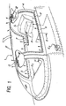
- -la figure 1 représente schématiquement une verrière d'avion munie du dispositif selon l'invention;
- - la figure 2 représente un agrandissement de la figure 1 au niveau de la section Il;
- - la figure 3 représente un agrandissement de la figure 1 au niveau de la section III;
- - la figure 4 représente un agrandissement de la figure 1 au niveau de la section IV.
- FIG. 1 schematically represents an airplane canopy provided with the device according to the invention;
- - Figure 2 shows an enlargement of Figure 1 at section II;
- - Figure 3 shows an enlargement of Figure 1 at section III;
- - Figure 4 shows an enlargement of Figure 1 at section IV.
Sur le figure 1 est représentée une verrière 1 d'un avion, comportant un élément transparent 2 maintenu dans un arceau avant 3, un arceau arrière 4 et deux bordures longitudinales 5 et 6, permettant également le maintien de l'élément transparent sur la verrière. Dans l'exemple présenté, celle-ci est articulée latéralement sur des charnières telles que 7 et son ouverture se fait par un basculement latéral. Elle pourrait être articulée différemment et basculer de l'avant vers l'arrière. Le dispositif selon l'invention pourrait s'appliquer également à une verrière à coulisses. Une telle verrière permet l'accès à l'habitacle de l'avion et son évacuation normale au sol. Un cordeau détonant 8, placé à la périphérie de la verrière est logé dans les bordures longitudinales 5 et 6 et dans les arceaux 3 et 4; son positionnement sera décrit plus en détail ultérieurement. Il est relié aux moyens de mise en détonation, non représentés, par une chaîne de transmission telle que 9.In Figure 1 is shown a canopy 1 of an airplane, comprising a transparent element 2 held in a front hoop 3, a rear hoop 4 and two longitudinal edges 5 and 6, also allowing the transparent element to be held on the canopy . In the example presented, the latter is articulated laterally on hinges such as 7 and its opening is effected by lateral tilting. It could be articulated differently and tilt from front to back. The device according to the invention could also be applied to a sliding canopy. Such a canopy allows access to the passenger compartment of the aircraft and its normal evacuation to the ground. A detonating
Ce dispositif pyrotechnique assure le découpage et l'éjection de l'élément transparent 2 de façon à faciliter l'évacuation d'urgence de l'équipage hors de l'habitacle de l'avion. La mise en détonation du cordeau pyrotechnique 8 est en général commandée par le mouvement de siège 5 ou tout début de sa phase d'éjection par tout moyen connu.This pyrotechnic device cuts and ejects the transparent element 2 so as to facilitate the emergency evacuation of the crew from the passenger compartment of the aircraft. The detonation of the
En cas de nécessité d'évacuation d'urgence au sol, par exemple en cas de crash, et alors que la verrière peut être bloquée par d'éventuelles déformations, la mise en détonation du cordeau pyrotechnique 8 peut être accomplie, indépendamment du siège éjectable S, par une commande manuelle. Celli-ci peut comprendre une poignée de déclenchement intérieure El et au moins une poignée de déclenchement extérieure E2, permettant le découpage de l'élément transparent et son éjection, sans intervention du siège éjectable, et pouvant être actionnées soit par un membre de l'équipage, soit par tout intervenant extérieur.In case of emergency evacuation on the ground, for example in the event of a crash, and when the canopy can be blocked by possible deformations, the detonation of the
Les différentes flèches représentées sur cette figure montrent, lors de la mise en action du dispositif pyrotechnique, la direction prise par les différentes impulsions produites par la détonation du cordeau 8.The different arrows shown in this figure show, when the pyrotechnic device is put into action, the direction taken by the different pulses produced by the detonation of the
Sur la figure 2, est représentée une section suivant Il de la bordure longitudinale 5 de la figure 1, la bordure 6 étant identique à cette dernière. Cette bordure longitudinale 5 comprend un logement 10 destiné à recevoir le bord de l'élément transparent 2 par l'intermédiaire d'un profilé d'accrochage à jonc 11 de type connu, réalisé en matériau composite. Ce profilé 11 comporte deux parois verticales telles que 12 auxquelles adhère l'élément transparent par collage, parois qui se rejoignent en 13 en enfermant le jonc 14. Les parois inclinées telles que 15 qui sont le prolongement des parois 12 du profilé d'accrochage délimitent avec la face inférieure 2' du bord de l'élément transparent 2 un espace garni d'un matériau de remplissage du type cellulaire ou autre. Le cordeau détonant 8 est disposé dans une gorge 16 pratiquée dans une face de la cavité formant le logement 10, appartenant à la partie interne de la bordure longitudinale 5. L'ouverture 16' de ladite gorge est située en regard de la paroi inclinée 15 et tournée vers l'intérieur de l'habitacle tandis que dans la même zone, contenant le cordeau, et afin de la renforcer, la bordure longitudinale 5 offre un renflement tel que 17. Un tel agencement du cordeau 8 a pour premier effet, lors de sa détonation, de découper le profilé 11 à l'endroit des parois 15 tandis que le second effet, dû à la haute pression instantanée des gaz, induit une impulsion maximale verticale diregée de bas en haut suivant la flèche F1 qui décolle les parois du profilé 11 de leur logement 10 et assure l'éjection de l'élément transparent au-dessus de l'habitacle.In Figure 2, there is shown a section along It of the longitudinal border 5 of Figure 1, the border 6 being identical to the latter. This longitudinal edge 5 comprises a housing 10 intended to receive the edge of the transparent element 2 by means of a rod fastening profile 11 of known type, made of composite material. This profile 11 has two vertical walls such as 12 to which the transparent element adheres by gluing, walls which join at 13 by enclosing the rod 14. The inclined walls such as 15 which are the extension of the walls 12 of the attachment profile delimit with the lower face 2 ′ of the edge of the transparent element 2 a space filled with a filling material of the cellular type or the like. The detonating
La figure 3 représente une section suivant le plan III de l'arceau avant 3 de la figure 1. Cet arceau est constitué de deux éléments structuraux: un élément interne 18 et un élément externe ou couvrejoint 19. Ces deux éléments prennent en sandwich un talon d'accrochage 20 en matériau composite offrant un logement 20' à deux parois, une paroi interne 21 et une paroi externe 22, destiné à recevoir l'élément transparent 2. La paroi interne 21 dépasse l'extrémité renflée formant renfort 23 de l'élément structural interne 18 de l'arceau et s'applique sur l'élément transparent sur une largeur plus importante que la paroi externe 22 dudit logement. L'élément transparent 2 est rendu solidaire de son talon d'accrochage 20 par collage et l'assemblage de l'ensemble est réalisé par un boulonnage tel que 24. Dans la face interne de l'élément 18, au droit de sa partie de renfort 23, est pratiquée une gorge 25. Une ouverture 25' de ladite gorge est située en regard de la paroi interne 21 et sensiblement en regard de l'extrémité de la paroi externe 22. Dans cette gorge est disposé le cordeau pyrotechnique 8 dont une première longueur est installée dans la bordure longitudinale 5. Ce positionnement du cordeau 8 ajouté à la forme du talon d'accrochage 20 de l'élément transparent 2 est tel que la détonation dutit cordeau a pour effet un découpage franc dudit élément et une impulsion importante dirigée de l'intérieur vers l'extérieur de l'habitacle comme l'indique la flèche F2. Le cordeau détonant 8 logé comme nous l'avons vu dans la bordure longitudinale 5, puis dans l'arceau avant 3, est ensuite disposé dans la bordure 6 de la même façon que dans la bordure 5. La mise en place de la suite du cordeau 8 dans l'arceau arrière 4, dont une section suivant IV de la figure 1 est représentée à la figure 4, s'effectue de la façon indiquée ci-après.FIG. 3 represents a section along plane III of the front arch 3 of FIG. 1. This arch consists of two structural elements: an internal element 18 and an external element or joint cover 19. These two elements sandwich a heel attachment 20 made of composite material offering a housing 20 'with two walls, an internal wall 21 and an external wall 22, intended to receive the transparent element 2. The internal wall 21 exceeds the bulged end forming reinforcement 23 of the internal structural element 18 of the arch and is applied to the transparent element over a greater width than the external wall 22 of said housing. The transparent element 2 is made integral with its hooking heel 20 by gluing and the assembly of the assembly is carried out by bolting such as 24. In the internal face of the element 18, in line with its part of reinforcement 23, a groove 25 is formed. An opening 25 ′ of said groove is located opposite the internal wall 21 and substantially opposite the end of the external wall 22. In this groove is disposed the
L'arceau arrière 4 est composé de deux éléments structuraux, à savoir un élément interne 26 et un élément externe ou couvre-joint 27. Ces deux éléments prennent en sandwich un talon d'accrochage 28 en matériau composite offrant un logement 28' à deux parois, une parois interne 29 et une paroi externe 30, destiné à recevoir l'élément transparent 2. La paroi interne 29 recouvre ce dernier sur une largeur moindre que la largeur de la paroi externe 30. L'élément transparent 2 est rendu solidaire de son talon d'accrochage 28 par collage et l'assemblage de l'ensemble est réalisé par un boulonnage 31. Dans la face interne de l'élément 26, dans la zone renforcée 32, est pratiquée une gorge 33. L'ouverture 33' de ladite gorge est située en regard de la paroi 29 et en regard également de la paroi externe 30. Dans la gorge 33 est disposé le cordeau détonant 8. Le positionnement de ce dernier et la forme du talon d'accrochage 28 sont tels que la détonation du cordeau provoque une rupture partielle de l'élément transparent 2 suivie d'un délaminage de son bord concourant à un effet de retenue temporaire sur l'impulsion dirigée de l'intérieur vers l'extérieur de l'habitacle comme l'indique la flèche F3.The rear hoop 4 is composed of two structural elements, namely an internal element 26 and an external element or joint cover 27. These two elements sandwich a hooking heel 28 made of composite material offering a housing 28 'for two walls, an internal wall 29 and an external wall 30, intended to receive the transparent element 2. The internal wall 29 covers the latter over a width less than the width of the external wall 30. The transparent element 2 is made integral with its attachment heel 28 by bonding and the assembly of the assembly is carried out by bolting 31. In the internal face of the element 26, in the reinforced zone 32, a groove 33 is formed. The opening 33 ′ of said groove is located opposite the wall 29 and also opposite the external wall 30. In the groove 33 is disposed the detonating
Les effets composés de la détonation du cordeau pyrotechnique 8 sur la périphérie de la verrière, c'est-à-dire découpage et décollage de l'élément transparent de verrière et impulsions dirigées de bas en haut et de l'intérieur vers l'extérieur de l'habitacle avec retenue sur l'arceau arrière, entraînent de façon concomitante un mouvement de basculement vers l'arrière de l'avion de l'élément transparent ainsi découpé, et son éjection à très grande vitesse libérant de ce fait la trajectoire du siège éjectable de tout obstacle.The compound effects of the detonation of the
Le dispositif pyrotechnique et le procédé d'éjection de l'élément transparent de la verrière peuvent être adaptés à tout type de verrière d'avion mono ou multiplaces. Dans le cas, par exemple, où la verrière est composée de deux éléments transparents avant et arrière, ceux-ci sont séparés par un arceau central unique dont la technologie sera celle qui est représentée sur la figure 3 pour la partie arrière de l'arceau et celle qui est représentée sur la figure 4 pour la partie avant. Dans un autre exemple de verrière composée de deux éléments transparents gauche et droit, ceux-ci sont séparés par un montant central longitudinal dont la technologie sera identique à celle qui est représentée sur la figure 2. Dans ces exemples de verrière comportant au moins deux éléments transparents, les chaînes pyrotechniques de découpage pourront être séparées et leur mise en détonation pourra être soit séparée, soit simultanée.The pyrotechnic device and the method for ejecting the transparent element from the canopy can be adapted to any type of single or multi-seater airplane canopy. In the case, for example, where the canopy is composed of two transparent elements, front and rear, these are separated by a single central arch, the technology of which will be that shown in FIG. 3 for the rear part of the arch. and that which is represented in FIG. 4 for the front part. In another example of a glass roof made up of two transparent elements, left and right, these are separated by a longitudinal central upright, the technology of which will be identical to that which is shown in FIG. 2. In these examples of glass roof comprising at least two elements transparent, the pyrotechnic cutting chains can be separated and their detonation can be either separate or simultaneous.
Claims (12)
Applications Claiming Priority (2)
| Application Number | Priority Date | Filing Date | Title |
|---|---|---|---|
| FR8015489A FR2486489A1 (en) | 1980-07-11 | 1980-07-11 | PYROTECHNIC DEVICE AND METHOD FOR CUTTING AND EJECTING A TRANSPARENT ELEMENT OF AIRCRAFT GLASS |
| FR8015489 | 1980-07-11 |
Publications (2)
| Publication Number | Publication Date |
|---|---|
| EP0044251A1 EP0044251A1 (en) | 1982-01-20 |
| EP0044251B1 true EP0044251B1 (en) | 1985-01-02 |
Family
ID=9244114
Family Applications (1)
| Application Number | Title | Priority Date | Filing Date |
|---|---|---|---|
| EP19810401103 Expired EP0044251B1 (en) | 1980-07-11 | 1981-07-08 | Pyrotechnic device for severing and jettisoning a transparent canopy |
Country Status (3)
| Country | Link |
|---|---|
| EP (1) | EP0044251B1 (en) |
| DE (1) | DE3168029D1 (en) |
| FR (1) | FR2486489A1 (en) |
Families Citing this family (5)
| Publication number | Priority date | Publication date | Assignee | Title |
|---|---|---|---|---|
| FR2542697B1 (en) * | 1983-03-14 | 1986-03-21 | Dassault Avions | METHOD AND PYROTECHNIC DEVICE FOR EJECTION OUTSIDE AN AIRPLANE |
| FR2559451B1 (en) * | 1984-02-09 | 1986-08-08 | Dassault Avions | CONNECTION DEVICE FOR A PYROTECHNIC CIRCUIT LEADING TO AN AIRCRAFT CANOPY |
| FR2619738B1 (en) * | 1987-08-31 | 1993-12-17 | Dassault Breguet Aviation | PROCESS FOR CREATING A SEPARATION IN A ROOM USING A PYROTECHNIC EXPANDABLE TUBE |
| AU7782601A (en) * | 2000-08-08 | 2002-03-22 | Yusupovich Khalidov Hamid | Aparc system for air passengers and load rescue |
| DE10112413C2 (en) * | 2001-03-15 | 2003-04-10 | Eurocopter Deutschland | Emergency exit hatch for an airworthy aircraft prototype |
Family Cites Families (4)
| Publication number | Priority date | Publication date | Assignee | Title |
|---|---|---|---|---|
| US3486410A (en) * | 1968-04-18 | 1969-12-30 | Mc Donnell Douglas Corp | Explosive severance means |
| FR2077846A1 (en) * | 1970-02-18 | 1971-11-05 | Dassault Aeronautique | |
| GB1383511A (en) * | 1971-01-15 | 1974-02-12 | Hawker Siddeley Aviation Ltd | Aircraft canopy emergency |
| US3919939A (en) * | 1974-11-01 | 1975-11-18 | Us Navy | Method and means for flash suppression |
-
1980
- 1980-07-11 FR FR8015489A patent/FR2486489A1/en active Granted
-
1981
- 1981-07-08 EP EP19810401103 patent/EP0044251B1/en not_active Expired
- 1981-07-08 DE DE8181401103T patent/DE3168029D1/en not_active Expired
Also Published As
| Publication number | Publication date |
|---|---|
| FR2486489B1 (en) | 1982-10-29 |
| EP0044251A1 (en) | 1982-01-20 |
| DE3168029D1 (en) | 1985-02-14 |
| FR2486489A1 (en) | 1982-01-15 |
Similar Documents
| Publication | Publication Date | Title |
|---|---|---|
| EP2733066B1 (en) | Method for automatically triggering an emergency buoyancy system for a hybrid helicopter | |
| FR2634171A1 (en) | PYROTECHNIC SYSTEM FOR PRACTICING A RELIEF OUTLET IN A WALL OF AN AIRCRAFT AND AN AIRCRAFT EQUIPPED WITH SAID SYSTEM | |
| EP1209077B1 (en) | Aircraft passenger boarding device and flying wing equipped with this device | |
| FR2478572A1 (en) | SAFETY INSTALLATION FOR AIRCRAFT | |
| EP0020226B1 (en) | Device for transporting and launching a plurality of projectiles contained within a container | |
| EP2743175B1 (en) | Sealed forward bulkhead of an aircraft including recesses for housing cockpit equipment and its fabrication method | |
| FR2766156A1 (en) | Glazing frame for helicopter window | |
| EP2064114A1 (en) | Locking and unlocking system for the cockpit door of an aircraft and door with such a system | |
| EP0013529B1 (en) | Glass pane provided with a pyrotechnical cutting device | |
| EP2586705A1 (en) | Aircraft equipped with a buoyancy system of a rotating element | |
| EP0044251B1 (en) | Pyrotechnic device for severing and jettisoning a transparent canopy | |
| EP1902757B1 (en) | Propulsion device for an agent contained in a cavity | |
| EP1142784A1 (en) | Aircraft door and aircraft equipped with such a door | |
| EP2735506A1 (en) | Method of mounting a floatation system on an aircraft, floatation system for an aircraft, and an aircraft | |
| FR2542697A1 (en) | METHOD AND PYROTECHNIC DEVICE FOR EJECTING OUTSIDE AN AIRCRAFT | |
| WO2017042165A1 (en) | Emergency opening system and method for an aircraft emergency door | |
| EP3409585B1 (en) | An aircraft provided with a buoyancy system, and a buoyancy method | |
| FR2772340A1 (en) | Emergency descent control parachute for helicopter | |
| EP3476718B1 (en) | Jettisonable vehicle window and vehicle comprising such window | |
| FR2634454A1 (en) | RESCUE UNIT FOR THE CREW OF SPACE CONVEYORS | |
| EP0225247B2 (en) | Parachute canopy | |
| EP0363543B1 (en) | Device to connect an escape slide or a life-raft to an aircraft | |
| FR2524858A1 (en) | DEVICE ARRANGEMENT FOR SEPARATING AND REMOVING WALL PARTS FROM CABIN ROOF OF STEERING STATIONS | |
| EP0211703B1 (en) | Plug for a solid propellant with two combustion chambers | |
| WO2019202257A2 (en) | System for launching a paraglider canopy from the stratosphere |
Legal Events
| Date | Code | Title | Description |
|---|---|---|---|
| PUAI | Public reference made under article 153(3) epc to a published international application that has entered the european phase |
Free format text: ORIGINAL CODE: 0009012 |
|
| AK | Designated contracting states |
Designated state(s): DE GB IT SE |
|
| 17P | Request for examination filed |
Effective date: 19820618 |
|
| ITF | It: translation for a ep patent filed |
Owner name: JACOBACCI & PERANI S.P.A. |
|
| GRAA | (expected) grant |
Free format text: ORIGINAL CODE: 0009210 |
|
| AK | Designated contracting states |
Designated state(s): DE GB IT SE |
|
| REF | Corresponds to: |
Ref document number: 3168029 Country of ref document: DE Date of ref document: 19850214 |
|
| PLBE | No opposition filed within time limit |
Free format text: ORIGINAL CODE: 0009261 |
|
| STAA | Information on the status of an ep patent application or granted ep patent |
Free format text: STATUS: NO OPPOSITION FILED WITHIN TIME LIMIT |
|
| 26N | No opposition filed | ||
| PGFP | Annual fee paid to national office [announced via postgrant information from national office to epo] |
Ref country code: GB Payment date: 19900629 Year of fee payment: 10 Ref country code: DE Payment date: 19900629 Year of fee payment: 10 |
|
| PGFP | Annual fee paid to national office [announced via postgrant information from national office to epo] |
Ref country code: SE Payment date: 19900702 Year of fee payment: 10 |
|
| ITTA | It: last paid annual fee | ||
| PG25 | Lapsed in a contracting state [announced via postgrant information from national office to epo] |
Ref country code: GB Effective date: 19910708 |
|
| PG25 | Lapsed in a contracting state [announced via postgrant information from national office to epo] |
Ref country code: SE Effective date: 19910709 |
|
| GBPC | Gb: european patent ceased through non-payment of renewal fee | ||
| PG25 | Lapsed in a contracting state [announced via postgrant information from national office to epo] |
Ref country code: DE Effective date: 19920401 |
|
| EUG | Se: european patent has lapsed |
Ref document number: 81401103.7 Effective date: 19920210 |