EP0044154A2 - Phase-locked loop frequency synthesizer including compensated phase and frequency modulation - Google Patents
Phase-locked loop frequency synthesizer including compensated phase and frequency modulation Download PDFInfo
- Publication number
- EP0044154A2 EP0044154A2 EP81302906A EP81302906A EP0044154A2 EP 0044154 A2 EP0044154 A2 EP 0044154A2 EP 81302906 A EP81302906 A EP 81302906A EP 81302906 A EP81302906 A EP 81302906A EP 0044154 A2 EP0044154 A2 EP 0044154A2
- Authority
- EP
- European Patent Office
- Prior art keywords
- signal
- phase
- modulation
- locked loop
- frequency
- Prior art date
- Legal status (The legal status is an assumption and is not a legal conclusion. Google has not performed a legal analysis and makes no representation as to the accuracy of the status listed.)
- Granted
Links
Images

Classifications
-
- H—ELECTRICITY
- H03—ELECTRONIC CIRCUITRY
- H03C—MODULATION
- H03C3/00—Angle modulation
- H03C3/02—Details
- H03C3/09—Modifications of modulator for regulating the mean frequency
- H03C3/0908—Modifications of modulator for regulating the mean frequency using a phase locked loop
- H03C3/0975—Modifications of modulator for regulating the mean frequency using a phase locked loop applying frequency modulation in the phase locked loop at components other than the divider, the voltage controlled oscillator or the reference clock
-
- H—ELECTRICITY
- H03—ELECTRONIC CIRCUITRY
- H03C—MODULATION
- H03C3/00—Angle modulation
- H03C3/02—Details
- H03C3/09—Modifications of modulator for regulating the mean frequency
- H03C3/0908—Modifications of modulator for regulating the mean frequency using a phase locked loop
- H03C3/0941—Modifications of modulator for regulating the mean frequency using a phase locked loop applying frequency modulation at more than one point in the loop
-
- H—ELECTRICITY
- H03—ELECTRONIC CIRCUITRY
- H03C—MODULATION
- H03C3/00—Angle modulation
- H03C3/02—Details
- H03C3/09—Modifications of modulator for regulating the mean frequency
- H03C3/0908—Modifications of modulator for regulating the mean frequency using a phase locked loop
- H03C3/0958—Modifications of modulator for regulating the mean frequency using a phase locked loop applying frequency modulation by varying the characteristics of the voltage controlled oscillator
-
- H—ELECTRICITY
- H03—ELECTRONIC CIRCUITRY
- H03C—MODULATION
- H03C2200/00—Indexing scheme relating to details of modulators or modulation methods covered by H03C
- H03C2200/0037—Functional aspects of modulators
- H03C2200/005—Modulation sensitivity
-
- H—ELECTRICITY
- H03—ELECTRONIC CIRCUITRY
- H03C—MODULATION
- H03C2200/00—Indexing scheme relating to details of modulators or modulation methods covered by H03C
- H03C2200/0037—Functional aspects of modulators
- H03C2200/005—Modulation sensitivity
- H03C2200/0054—Filtering of the input modulating signal for obtaining a constant sensitivity of frequency modulation
Definitions
- the first modulation path includes circuitry for integrating the applied modulation signal and for summing the integrated signal with the signal provided by the phase-locked loop phase detector.
- the second modulation path includes circuitry for summing the applied modulation signal with the frequency control signal (i.e., the loop error signal) that is coupled to the phase-lock loop. voltage-controlled oscillator (VCO).
- VCO voltage-controlled oscillator
- phase-lock loop is configured to provide carrier frequencies over an extended frequency range (e.g., an octave or more) and when additional circuitry is included within the phase-lock loop.
- the frequency division ratio, N in such a system is not a constant, but is varied to select the desired carrier frequency.
- the gain factor of the system VCO (K v ) is not constant, but exhibits a somewhat unpredictable variation with frequency unless, for example, specialized circuit arrangements such as a YIG- tuned voltage-controlled oscillator are employed.
- phase detector 22 effectively compares the phase of the signal supplied by the programmable divider 18 with the phase of a reference signal f (applied to the second input terminal of the phase detector 22), and supplies an error signal having a magnitude proportional to the phase difference between the reference signal and the signal supplied by programmable divider 18.
- DAC 48 is effectively a variable attenuator that is controlled by a parallel format digitally-encoded signal (denoted by the double arrow in FIGURE 1) so as to equalize the system for frequency-related variations in the gain factor, K vv , O f VCO 12.
- the above- stated transfer function of the tracking phase-locked loop of FIGURE 2 (Equation 4) can be satisfactorily simulated by the active network depicted in FIGURE 3 so that the system frequency and phase modulation characteristic can be made independent of modulating frequency by arranging the embodiment of FIGURE 1 in accordance with the constraints set forth in Equation 3.
- the depicted active network includes three operational amplifiers 120, 122 and 124 wherein the inverting input terminal of operational amplifier 120 is connected for receiving the modulation signal supplied by DAC 48 via a resistor 126.
Abstract
Description
- This invention relates to phase and frequency modulation and more particularly to apparatus and methods for precise phase and frequency modulation of phase-locked loop frequency synthesizers.
- It is known in the art that a phase-locked loop circuit can be angle modulated (phase or frequency modulated) over a wide band of frequencies that includes frequencies both greater than and less than the loop bandwidth by injecting modulation components at two separate circuit nodes of the phase-locked loop system. For example, U.S. patent No. 4,052,672, issued to Enderby et al. discloses a programmable divide-by-N phase-locked loop system wherein frequency modulation is effected over a relatively wide range of modulation frequencies by phase modulating the system via a first modulation path for all frequencies within the loop bandwidth and by frequency modulating the loop via a second modulation path for all modulating frequencies outside the loop bandwidth. More specifically, in such a prior art arrangement, the first modulation path includes circuitry for integrating the applied modulation signal and for summing the integrated signal with the signal provided by the phase-locked loop phase detector. The second modulation path includes circuitry for summing the applied modulation signal with the frequency control signal (i.e., the loop error signal) that is coupled to the phase-lock loop. voltage-controlled oscillator (VCO). Relatively flat modulation characteristics are achieved in such a system by establishing the gain constant (i.e., sensitivity) of the modulation path that includes the integrator circuit substantially equal to the reciprocal of the loop bandwidth. ,
- An alternative prior art arrangement frequency modulates the phase-locked loop reference oscillator, rather than phase-modulating the system phase detector. More specifically, such a prior arrangement differs from the above-described system in that the integrator circuit is omitted and the first modulation path controls the frequency of a reference oscillator (e.g., a voltage-controlled crystal oscillator) that provides the reference signal to the phase-locked loop phase detector. In such a system relatively flat modulation will be attained as long as the gain factor associated with the path including the voltage-controlled crystal oscillator is established so that the product of the frequency deviation of the reference oscillator, multiplied by frequency division ratio (N) of the phase-locked loop is equal to the deviation produced by the voltage-controlled oscillator that supplies the system output signal.
- Although prior art systems of the above-mentioned types may provide satisfactory operation under some conditions, disadvantages and draw- backs are encountered when the phase-lock loop is configured to provide carrier frequencies over an extended frequency range (e.g., an octave or more) and when additional circuitry is included within the phase-lock loop. In particular, the frequency division ratio, N, in such a system is not a constant, but is varied to select the desired carrier frequency. Moreover, the gain factor of the system VCO (Kv) is not constant, but exhibits a somewhat unpredictable variation with frequency unless, for example, specialized circuit arrangements such as a YIG- tuned voltage-controlled oscillator are employed. With respect to the inclusion of additional circuitry within the phase-lock loop, such circuitry is often required in order to provide additional features or effect operation beyond the capabilities of a basic phase-lock loop. For example, the copendingU.S. pattent application (Serial No.168,066) of Floy D. Erps,and Raymond L. Friend, entitled PHASE-LOCK LOOP FREQUENCY SYNTHESIZER, filed 14th July 980 and corresponding to our EPC Patent Application 81302908.9 filed on the same day as this application. discloses a programmable divide-by-N phase-lock loop which provides frequency resolution greatly exceeding that of conventionally-arranged phase-locked loops wherein some embodiments of the disclosed system include a complete phase-locked loop that is embedded in the feedback path of the frequency synthesizer loop. This additional phase-locked loop, in effect, serves as a tracking filter which attenuates spurious signal components produced by a single-sideband mixer circuit.
- The high resolution phase-locked loop system disclosed in the above-mentioned patent application of Floyd Erps (et al.); and other phase-locked loop arrangements that have additional frequency-sensitive networks in the loop feedback path do not exhibit flat modulation characteristics when modulated by the previously-discussed prior art techniques. Further, the variation in the frequency division ratio is that required in order to provide the desired carrier frequencies and frequency-related deviations in the gain factor of the VCO of a phase-locked loop system can easily prevent a system from attaining a desired modulation flatness, including the high resolution phase-locked loop system disclosed in the above-mentioned patent application of Erps et al.
- Accordingly, it is an object of this invention to provide a circuit arrangement for angle modulation of a phase-locked loop system which is augmented with frequency-sensitive components or networks that are embedded in the phase-locked loop feedback path.
- It is another object of this invention to provide a signal source that can be selectively phase or frequency modulated wherein the signal source includes compensation for carrier frequency-related variations in the gain factors associated with the loop VCO and compensation for changes in the loop frequency division ratio as well as compensation for variations caused by frequency-sensitive networks that are embedded in the phase-locked loop feedback path.
- Still further, it is an object of this invention to provide a modulation compensation network for a high resolution phase-locked loop system of the type disclosed in the above-referenced patent application of Floyd D. Erps et al.
- In accordance with this invention, a compensator network, installed in the signal path which supplies the modulation signal to the loop phase detector, substantially reduces frequency-related signal variation that is induced by a audio frequency-sensitive network in the loop feedback path and would otherwise preclude use of the previously-mentioned frequency modulation arrangements. For example, in the type of modulated phase-locked loop system disclosed by the previously-referenced patent to Enderby et al., a compensator network configured in accordance with this invention is connected in cascade with the integrator circuit. In the prior art system which employs a frequency-modulated voltage-controlled crystal reference oscillator, the compensator network is connected in cascade with the oscillator frequency control port. In either case, the compensator network is arranged so as to exhibit a transfer function that is equal to, or at least approximates, the transfer function of the frequency-sensitive network within the phase-locked loop feedback path which would otherwise prevent the system from exhibiting a flat modulation characteristic.
- To prevent variations in the modulation characteristic caused by changes in the VCO gain factor, the level of the modulation signal that is commonly coupled to both modulation paths is adjusted as a function of carrier frequency (RF frequency) and in inverse proportion to carrier frequency-related changes in VCO gain factor. Similarly, the gain factor of the loop phase detector is controlled as a function of the selected frequency to eliminate changes in loop bandwidth and modulation characteristic that would otherwise occur. In the disclosed embodiments, compensation for changes in VCO gain factor, Kv, is effected through the use of a multiplying-type digital-to-analog converter (DAC) unit which, in effect, serves as a variable attenuator that establishes the amplitude of the modulating signal. Compensation for changes in loop bandwidth is effected with a second DAC, which is arranged to control the current supplied to a conventional frequency/phase detector.
- In accordance with another aspect of the invention, the disclosed embodiment is arranged to selectively configure the system as a frequency-modulated phase-lock loop or a phase-modulated phase-lock loop. In this regard, the integrator circuit that couples the modulation signal to the system phase detector is configured for operation as an amplifier when a switch that is included in the integrator/amplifier arrangement is activated. In a like manner, an amplifier within the modulation path that supplies a signal to the VCO frequency control terminal is arranged for operation as a differentiator circuit when operation in the phase-modulated mode is initiated. Regardless of whether the system is operated as a phase-modulated or frequency-modulated phase-lock loop, the previously-mentioned compensator unit and compensation for variations in system loop gain and VCO gain factor permit modulation at frequencies both inside and outside the loop bandwidth while providing a relatively constant modulation characteristic over a wide range of carrier frequencies.
- The disclosed embodiment is configured to provide substantially flat modulation with a phase-locked loop configured in the manner disclosed in the previously-mentioned patent application of Floyd D. t this embodiment, the compensator network includes three operational amplifier stages having local feedback networks and overall feedback which establishes a transfer function that approximates that of the complete phase-locked loop network that is embedded in the feedback path of the phase-locked loop which serves as a frequency synthesizer.
- Other objects and advantages of the present invention will be apparent to one of ordinary skill in the art upon consideration of the following description taken together with the accompanying drawing wherein:
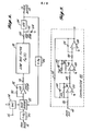
- FIGURE 1 is a blocked diagram which illustrates the basic arrangement of the invention embodied for use with a phase-locked loop of the type disclosed in the previously-mentioned patent application of Floyd D. Erpset al.,
- FIGURE 2 depicts a phase-locked loop which is embedded in the feedback path of the frequency synthesizer of FIGURE 1 to serve as a tracking filter; and
- FIGURE 3 illustrates an active circuit arrangement which simulates the transfer function of the phase-locked loop depicted in FIGURE 3 and serves as the compensator unit of the arrangement of FIGURE 1.
- The invention will now be described relative to an embodiment thereof that is configured for use with an augmented phase-locked loop frequency synthesizer of the type disclosed in the previously-referenced patent application of Floyd D. Erps et al., wherein a second phase-locked loop is embedded in the feedback path of a phase-locked loop frequency synthesizer. In this regard, and with initial reference to FIGURE 1, the frequency synthesizer or main loop of the disclosed embodiment includes a voltage-controlled oscillator (VCO) 12 which supplies a signal, at frequency fo, to the
system output terminal 14 and to one input port of amixer circuit 16. As is indicated in FIGURE 1, a signal having a frequency f is coupled to the second input port of themixer 16. In the preferred arrangements of the systems disclosed in the patent application of Erpset al.,mixer 16 is a conventional single sideband mixer that is arranged to provide either an upper sideband signal (at a frequency of f + fs) or a lower sideband signal (at a frequency fo - fs) that cause the depicted phase-locked loop to supply an output frequency that differs from that of a conventional programmable divide-by-N phase-locked loop. In particular, when a lower sideband mixer is employed asmixer 16, a signal having a frequency equal to fo - fs is coupled to aprogrammable divider 18, which supplies a signal having an average frequency of (fo- fs)/N to one input port of a conventionalphase detector circuit 22. As shall be described hereinafter, the depictedcircuit stage 20, which couples the signal frommixer 16 toprogrammable divider 18 is a phase-locked loop arranged to substantially attenuate spurious signals generated withinmixer 16. - Regardless of the arrangement of
circuit stage 20,phase detector 22 effectively compares the phase of the signal supplied by theprogrammable divider 18 with the phase of a reference signal f (applied to the second input terminal of the phase detector 22), and supplies an error signal having a magnitude proportional to the phase difference between the reference signal and the signal supplied byprogrammable divider 18. - The error signal supplied by
phase detector 22 is coupled to afrequency control terminal 26 ofVCO 12 by afilter unit 24. As is indicated in FIGURE 1,filter unit 24 is of the type conventionally employed in phase-locked loop systems. In this regard, the first circuit stage offilter unit 24 is commonly identified as the loop filter and includes anoperational amplifier 28 having its inverting input terminal connected for receiving the signal supplied byphase detector 22 and for receiving modulation component that is supplied via a first modulation path that is described hereinafter. A resistor 30 and acapacitor 32 are serially connected between the inverting input and output terminals ofoperational amplifier 28 to form a feedback path and aresistor 34 couples the signal supplied by the depicted loop filter to a low-pass filter stage 36. Low-pass filter stage is a conventionally-arranged passive or active network which is generally configured to eliminate signal components at the reference frequency fr and supplies the system error signal tofrequency control terminal 26 ofVCO 12 via a resistor 38. As is shown in FIGURE 1, resistor 38 is one element of a conventional lead-lag network that also includesresistor 40 andcapacitor 42, which are connected in series between circuit common potential and .the electrode of resistor 38 that is connected toVCO 12. - In view of the above-discussed arrangement it can be recognized that, in the absence of the hereinafter-discussed modulation signal,
VCO 12 will be locked to a frequency fo = Nfr + fs, which exhibits improved resolution over a conventional programmable divide-by-N phase-locked loop system that supplies an output signal at a frequency Nfr. In this regard, the phase-locked loop systems disclosed in the previously-mentioned patent application of Floyd D. Erpset al., are augmented with additional circuit arrangements which cause the system VCO to lock at a frequency equal to Nfr ± fs ± fdl where fd is the frequency of a control signal that is applied to an additional circuit stage that interconnects the single-sideband mixer 16 and theprogrammable frequency divider 18. Since, the structure of such pulse incrementor circuits and the associated operational aspects of the overall arrangement disclosed in the Erps et al., patent application are not essential to the operation of this invention, a more detailed discussion of such a system is not presented herein, but is incorporated by reference. - Turning now to modulation of the above-discussed phase-locked loop, the embodiment of FIGURE 1 includes two modulation paths so as to permit modulation at rates both inside and outside the bandwidth of the phase-locked loop and is arranged for either frequency or phase modulation. In the arrangement of FIGURE 1, the modulation signal Vm is applied to a
terminal 42 and commonly coupled to the input ports of acompensater unit 44 and an amplifier/differentiator unit 46 via a multiplying-type digital-to-analog converter (DAC) 48. As shall be recognized upon fully understanding the manner in which the invention operates to provide precise frequency compensation,DAC 48 is effectively a variable attenuator that is controlled by a parallel format digitally-encoded signal (denoted by the double arrow in FIGURE 1) so as to equalize the system for frequency-related variations in the gain factor, Kvv,Of VCO 12. - To form one of the modulation paths, an amplifier/
differentiator 46 couples the signal supplied byDAC 48 to a secondfrequency control terminal 50 ofVCO 12. In this regard, those skilled in the art will recognize that various conventional VCO's are available which, in effect, include circuitry for summing two frequency control signals. For example, various VCO's of the type indicated in FIGURE 1 are available wherein individual frequency control signals can be coupled to the two electrodes of avaractor diode 52 which controls the VCO output frequency. Moreover, it can be recognized that equivalent operation can be attained by utilizing a conventional signal summing unit in conjunction with a VCO having a single frequency control terminal. Regardless of the type of VCO employed, amplifier/differentiator 46 is selectively operable for either amplifying or differentiating the modulation signal supplied toVCO 12 when the system is being utilized for frequency modulation (FM) or phase modulation (PM), respectively. In particular, amplifier/differentiator 46 includes an operational amplifier 54 having its output terminal coupled toterminal 50 ofVCO 12 via asignal inverter 55 and a voltage divider formed byresistors feedback resistor 56 is connected between the output terminal and the inverting input terminal of operational amplifier 54. The input terminal of amplifier 54 is coupled to a first contact of aswitch 58 via acapacitor 60 and is coupled to a second contact of theswitch 58 via aresistor 62.Switch 58, which is symbolized in FIGURE 1 as a single-pole double-throw switch having the wiper contact thereof connected for receiving the signal supplied byDAC 48, is generally realized by one or more semiconductor circuits, such as those utilizing field- effect transistors. Regardless of the structure utilized, whenswitch 58 is in the depicted FM position, amplifier/differentiator 46 forms a conventional inverting operational amplifier configuration having a gain equal to -R56/R62. On the other hand, whenswitch 58 is activated to the PM state, amplifier/differentiator 46 forms an operational amplifier differentiator circuit, which effects phase modulation ofVCO 12 for modulation rates exceeding the phase-locked loop bandwidth. - To form the second modulation path, an integrator/
amplifier 64 couples the signal supplied bycompensator 44 to the inverting input terminal ofoperational amplifier 28, which forms the loop filter offilter unit 24. As shall be described hereinafter,compensator unit 44 includes a network that counteracts the audio frequency-related variations in modulation that would otherwise be induced bynetwork 20 which is located in the phase-lock loop feedback path. Integrator/amplifier 64 includes anoperational amplifier 68 having its inverting input terminal connected to the wiper contact of aswitch 70 and connected for receiving the signal supplied bycompensator 64 via aninput resistor 72. The output terminal ofoperational amplifier 68 is coupled to the inverting input terminal ofoperational amplifier 28 via aresistor 74 and is connected to the FM and PM contacts ofswitch 70 via acapacitor 76 and aresistor 78, respectively. - Those skilled in the art will recognize that integrator/
amplifier 64 forms a conventional operational amplifier integrator circuit whenswitch 70 is activated to the FM state. On the other hand, whenswitch 70 is activated to the PM state, integrator/amplifier 64 functions as a conventional inverting operational amplifier stage having a gain substantially equal to -R78lR72' - With regard to the use of inverting and noninverting circuit stages in the first and second modulation paths it should be noted that both paths should exhibit the same input signal to output signal phase relationship. That is, if one modulation path is arranged so that an audio modulation signal applied to terminal 42 causes a decrease (increase) in signal phase or frequency, the other modulation path must be arranged to exhibit a like-type of change in signal phase or frequency.
- Reference will now be made to FIGURE 2, which depicts a phase-locked loop of the type embedded in the feedback path of the phase-locked loop frequency synthesizer disclosed in the previously-mentioned patent application of Floyd D. et al., and hence corresponds to network 20 of the embodiment of the invention depicted in FIGURE 1. In this arrangement, a
frequency divider 80 receives the signal supplied by single sideband mixer 16 (FIGURE 1) at the frequency fo - fs, where, as previously described, fo is the frequency of theVCO 12 and fs is the frequency of the signal supplied to the second input port of thesingle sideband mixer 16. The signal supplied byfrequency divider 80 is coupled to the first input port of aconventional phase detector 82 having the second input port thereof connected for receiving the signal supplied by aVCO 84 via afrequency divider 86. As is the case with the main loop of the frequency synthesizer arrangement, the signal supplied by thephase detector 82 is coupled to the frequency control terminal of theVCO 84 via a cascaded loop filter, low-pass filter, and lead-lag network. In this regard, the loop filter includes anoperational amplifier 88 having aresistor 90 andcapacitor 92 serially connected to form a feedback path with aresistor 94 being connected to couple the signal supplied byoperational amplifier 88 to the input of the low-pass filter stage 98. Like the low-pass filter 36 utilized in the main phase-locked loop, low-pass filter 98 is a conventional active or passive filter network. Similarly, the lead-lag network employed in the phase-lock loop of FIGURE 2 is structurally equivalent to that of the main loop, being formed by tworesistors capacitor 104 that are connected as a voltage divides between the output terminal of the low-pass filter and circuit common with the junction between the resistors being connected to the frequency control terminal ofVCO 84. - As previously mentioned, the phase-locked loop arrangement of FIGURE 2 is embedded in the feedback path of the frequency synthesizer loop (FIGURE 1) and serves as a tracking filter that substantially reduces spurious signal components introduced by nonlinear operation of
mixer 16. In this arrangement, thefrequency divider 80 is utilized to prescale the frequency f - fs of the signal supplied by thesingle sideband mixer 16 of FIGURE 1 and thereby supply a reference frequency of (fo - fs)/Na to thephase detector 82, where N is the frequency division ratio offrequency divider 80. Such prescaling is advantageous in that it reduces the frequency of operation ofphase detector 82 and improves circuit operation when a modulating signal is applied. Since thefrequency divider 86 also exhibits a division ratio of N , the signal supplied byVCO 84 exhibits the original frequency, fo - fs. - The manner in which the invention compensates for frequency-related variations in the feedback signal of the main phase-lock loop that are induced by the additional phase-lock loop of FIGURE 2 (or by other structure) and further compensates for other frequency-related variations that affect modulation flatness can best be described in terms of the modulation transfer function of the arrangement depicted in FIGURE 1. In this regard it can be shown that the modulation characteristic when the system is being frequency modulated is:

- From
Equation 1 it can be shown that the system of FIGURE 1 will exhibit a constant modulation transfer function:


differentiator 46 when operating in the PM mode and A4 = R78/R72 is the gain of integrator/amplifier 64 in the PM mode. - Thus, the system will exhibit a constant (flat) phase modulation transfer function:


- Accordingly, to provide flat modulation characteristics in both the frequency modulation (FM) and phase modulation (PM) modes, the embodiment of FIGURE 1 is configured so that the transfer function of the compensator 44 (L(s)) is identically equal to, or at least approximates, the transfer function of the frequency-sensitive network embedded in the feedback path of the main loop (C(s)) (i.e., tracking phase-locked
loop 20 of FIGURES 1 and 2) over the entire range of carrier frequencies. In addition, from the above set forth equations, it can be seen that the system should be arranged with:
- The above set forth relationships between the various circuit parameters do not impose strict design constraints, but, in fact, are rather easily satisfied. In this regard, operation of the system of FIGURE 1 is determined by a greater number of circuit parameters than is the operation of prior art arrangements such as that disclosed in the previously-mentioned patent to Enderby et al. This permits greater design freedom and provides a greater opportunity to optimize system performance.
- To compensate for the changes in VCO gain factor (Kv) that occur with respect to a relatively wide range of carrier frequencies, the embodiment of FIGURE 1 includes
DAC 48, which adjusts the level of the applied modulation signal (Vm') by an amount necessary to offset a change in Kv. In particular, the digitally-encoded signal supplied toDAC 48 is selected so as to multiply the modulation signal applied toterminal 42 by a factor that is proportional to 1/Kv. For example, in one embodiment of the invention, the frequency range of the main loop is subdivided into a plurality of contiguous subbands, each spanning an equal frequency interval. In this arrangement, the subband associated with each particular system frequency can be identified by the integer portion of the ratio B = (fx - fa)/ Af, where B denotes the subband number, f denotes the frequency of interest, fa indicates the lowest system frequency and Δf indicates the frequency interval defined by each subband. Using this method of identification, digitally-encoded signals that provide the proper compensation for each subband are stored in a programmable read-only memory (PROM) of the embodiment being discussed. As each particular frequency is selected, a microprocessor unit determines the associated subband through use of the above-mentioned relationship; accesses the appropriate stored value and supplies the digitally-encoded signal toDAC 48. - The embodiment of FIGURE 1 also includes an additional digital-to-analog converter (DAC) 110 which controls the gain factor Kp of
phase detector 22 so as to maintain a constant loop bandwidth at all selected frequencies, i.e., vary Kp in proportion to N/Kv for all possible carrier frequencies (Nfr - fs, for the embodiment of FIGURE 1). Various methods can be employed for supplying the necessary digitally-encoded signal to DAC 110 and for suitably adjusting the gain factor ofphase detector 22. For example, in the above-mentioned embodiment of the invention which utilizes a microprocessor and a programmable read-only memory, digitally-encoded values appropriate to each of the above-mentioned subbands can be stored in the PROM and supplied to DAC 110 as each frequency is selected. Regardless of the technique employed,phase detector 22 can be, for example, a conventionally-arranged frequency/phase detector wherein a current supplied to the phase detector establishes the value of the gain coefficient K . - Turning now to describing suitable structure of a
compensator 44 for use with the embodiment of FIGURE 1, it can be shown that the ratio of output phase to input phase, φ oc/φ ic, for the tracking phase-lock loop that is . embedded in the feedback path of the main loop and depicted in FIGURE 2 is:


frequency divider 86, and the gain factors ofVCO 84 andphase detector 82 and Fa(s) is the transfer characteristic of low-pass filter 98. - As is indicated in FIGURE 3, if desired or necessary, a multiplying-type digital-to-analog converter (DAC) 114 can be included in an embodiment of the invention to maintain the bandwidth of the phase-locked loop depicted in FIGURE 2 substantially constant. In this regard, in the arrangement of FIGURE 2, an analog signal (DC signal) is applied to the analog input of
DAC 114 via aterminal 116. Digitally-encoded information which will maintain the loop bandwidth substantially constant is applied toDAC 114, for example, by utilizing the above-mentioned arrangement of a microprocessor which accesses data stored in a PROM on the basis of the selected system frequency. - Regardless of whether or not
DAC 114 is employed, the above- stated transfer function of the tracking phase-locked loop of FIGURE 2 (Equation 4) can be satisfactorily simulated by the active network depicted in FIGURE 3 so that the system frequency and phase modulation characteristic can be made independent of modulating frequency by arranging the embodiment of FIGURE 1 in accordance with the constraints set forth in Equation 3. Referring to FIGURE 3, the depicted active network includes threeoperational amplifiers operational amplifier 120 is connected for receiving the modulation signal supplied byDAC 48 via aresistor 126. The inverting input terminals ofoperational amplifiers operational amplifiers resistors resistor 132 supplies multistage feedback from the output terminal ofoperational amplifier 124 to the inverting input terminal ofoperational amplifier 120. In addition, each operational amplifier includes a local feedback network such as thecapacitor 134 that is connected between the output terminal and inverting input terminal ofoperational amplifier 124. With respect tooperational amplifier 122, the local feedback network consists of aresistor 136 andcapacitor 138 that are connected in series with one another and in parallel with both acapacitor 140 andresistor 142. As is further illustrated in FIGURE 3, the local feedback network foroperational amplifier 120 includes a serially-connectedresistor 144 andcapacitor 146 that are connected in parallel with a capacitor 148. - Basically, the portion of the circuit of FIGURE 3 that includes
operational amplifier 120,resistor 126 and the feedback network consisting ofresistor 144 andcapacitor 146 simulatesphase detector 82 andloop filter 92 of the phase-lock loop depicted in FIGURE 2 whereas all circuit components associated withoperational amplifier 122, exceptfeedback capacitor 140, simulate the lead-lag network of FIGURE 2 (resistors operational amplifier 124 simulates theVCO 84 of FIGURE 2. In the arrangement of FIGURE 3, the low-pass filter of FIGURE 2 is simulated by two-real circuit poles introduced by thefeedback capacitors 140 and 148. More specifically, it can be shown that the transfer function of the active network depicted in FIGURE 3 is:


- If all resistors except R142 exhibit a common value, R, Equation 3 can be expressed as:


- Comparing the transfer function for the
compensator 44 depicted in FIGURE 3 (Equation 6) with the transfer function, which is set forth in Equation 4, for the tracking phase-locked loop of FIGURE 2 that is used to augment the main phase-locked loop of FIGURE 1, it can be seen that the transfer functions would be of identical form if Fa(s)= P3P4/[(s + P3)(s + P4)]. In this regard, and as previously mentioned, it has been determined that the circuit poles P3 and P4 that are established in the transfer characteristic of the active network of FIGURE 3 bycapacitors 140 and 148, respectively, provide a satisfactory simulation of the low-pass filter utilized in the phase-locked loop of FIGURE 2. - More specifically, although a filter arrangement identical to that utilized as the low-pass filter in the arrangement of FIGURE 2 could be connected in cascade with the amplifier stages of the simulated network that is depicted in FIGURE 4 to provide a more accurate simulation of the phase-locked loop of FIGURE 2, the improved accuracy attained does not justify the additional circuit complexity and cost. If necessary or desired, computer-aided design techniques can be employed to optimize the location of circuit poles P3 and P4, i.e., determine optimum values of
capacitors 140 and 148. - With continued reference to the transfer function for the phase-locked loop of FIGURE 2 (Equation 4) and the simulated representation of the phase-locked loop that is illustrated in FIGURE 3 (Equation 5), it can be seen that establishing the respective circuit zeroes equal to one another requires that R90C92 = R144C146 and that R102C104 = R 136 C 138' Further, it can be seen that setting the pole at p1 of Equation 4 equal to the pole at P2 in Equation 6 requires that (R 94 + R100 + R102)C102 = R142C138. As previously stated, it is also necessary to set the bandwidth of the
compensator network 40 substantially equal to the bandwidth of the phase-locked loop depicted in FIGURE 2. The bandwidth ω c of the compensation network is equal to (R144R136)/(R132R128R130C134), which reduces to .1/(RC134) under the assumption that all resistors in the arrangement of FIGURE 3 (except resistor 142) exhibit a resistance value of R. Thus, establishing the bandwidth of the two networks equal to one another requires that 1/(RC134) = KpaKvaKa/Na, where the parameters are identical to those previously defined for FIGURE 2. - It should be recognized that embodiments of the invention will often utilize conventional integrator and differentiator arrangements that are more complex than those disclosed herein. In such embodiments of the invention or under other circumstances in which the transfer characteristic of one of the modulation paths is changed or altered, compensatory alterations should be included in the other modulation path. Thus, for example, when a differentiator utilizing a resistor in series with
capacitor 60 is utilized the circuit pole introduced in the transfer function of the differentiator should be offset by introducing a corresponding pole into the transfer function of the amplifier network utilized in integrator/amplifier 64. For example, a small capacitor may be connected in parallel withresistor 78. - Those skilled in the art will also recognize that the embodiment of the invention disclosed herein is exemplary in nature and that many variations and modifications can be made without exceeding the scope and the spirit of the invention. For example, although the invention is disclosed in terms of a high resolution phase-lock loop of the type described in the previously-mentioned patent application of Floyd D. Erps et al., the mathematical relationships set forth herein demonstrate that the invention can be practiced in any situation wherein frequency-sensitive networks or components are embedded in any presently- known type of phase-lock loop. For example, the invention has been satisfactorily embodied with a low noise phase-lock loop arrangement of the type disclosed in the copending U.S. Patent Applications Serial Nos. 168,065 and 168,524 of Donald L. Meyer and Kingsley W. Craft, respectively entitled "Controlled Frequency Signal Source Apparatus Including A Feedback Path For The Reduction Of Phase Noise" and "Frequency Modulated Phase-Locked Signal Source", each of which patent applications was filed on 14th July 1980 and respectively corresponding to our EPC Patent Applications Nos. 81302905.5 and 81302907.1 filed on the same day as this application. Further, the invention can be practiced in the previously mentioned type of prior art phase-locked loop system wherein the modulation signal that is coupled to the phase detector modulates a reference oscillator which supplies the reference signals to the phase detector input port. In such a system, a compensator that is configured in the manner described herein is installed in the signal path that couples the modulating signal to the frequency control port of the reference oscillator.
Claims (11)
Applications Claiming Priority (2)
| Application Number | Priority Date | Filing Date | Title |
|---|---|---|---|
| US168170 | 1980-07-14 | ||
| US06/168,170 US4313209A (en) | 1980-07-14 | 1980-07-14 | Phase-locked loop frequency synthesizer including compensated phase and frequency modulation |
Publications (3)
| Publication Number | Publication Date |
|---|---|
| EP0044154A2 true EP0044154A2 (en) | 1982-01-20 |
| EP0044154A3 EP0044154A3 (en) | 1982-06-16 |
| EP0044154B1 EP0044154B1 (en) | 1985-05-02 |
Family
ID=22610414
Family Applications (1)
| Application Number | Title | Priority Date | Filing Date |
|---|---|---|---|
| EP81302906A Expired EP0044154B1 (en) | 1980-07-14 | 1981-06-26 | Phase-locked loop frequency synthesizer including compensated phase and frequency modulation |
Country Status (3)
| Country | Link |
|---|---|
| US (1) | US4313209A (en) |
| EP (1) | EP0044154B1 (en) |
| DE (1) | DE3170262D1 (en) |
Cited By (8)
| Publication number | Priority date | Publication date | Assignee | Title |
|---|---|---|---|---|
| GB2183946A (en) * | 1985-12-06 | 1987-06-10 | Plessey Co Plc | Frequency synthesiser |
| EP0339605A2 (en) * | 1988-04-26 | 1989-11-02 | Japan Radio Co., Ltd | Phase-locked loop type synthesizer having modulation function |
| GB2228840A (en) * | 1989-03-04 | 1990-09-05 | Racal Dana Instr Ltd | Frequency synthesisers |
| EP0401947A2 (en) * | 1989-06-07 | 1990-12-12 | Robert Bosch Gmbh | PLL oscillator circuit modulatable by an analog, low frequency modulating voltage |
| GB2196196B (en) * | 1986-08-28 | 1990-12-19 | Mitsubishi Electric Corp | Pll frequency synthesizer |
| EP0415649A2 (en) * | 1989-09-01 | 1991-03-06 | Delco Electronics Corporation | Compensated phase locked loop circuit |
| EP0718963A1 (en) * | 1994-12-22 | 1996-06-26 | AT&T Corp. | Method and apparatus for broadband frequency modulation of a phase-locked frequency synthesizer |
| US5589795A (en) * | 1993-12-23 | 1996-12-31 | Nokia Mobile Phones Ltd. | Method and arrangement for controlling a loop filter |
Families Citing this family (29)
| Publication number | Priority date | Publication date | Assignee | Title |
|---|---|---|---|---|
| JPS58105631A (en) * | 1981-12-17 | 1983-06-23 | Nec Corp | Frequency modulating transmitter |
| FR2561468B1 (en) * | 1984-03-13 | 1989-10-20 | Thomson Csf | ACTIVE MICROWAVE FILTER |
| US4771248A (en) * | 1985-07-17 | 1988-09-13 | Hughes Aircraft Company | Fast phase-lock frequency synthesizer |
| US4668922A (en) * | 1985-07-17 | 1987-05-26 | Hughes Aircraft Company | Fast phase-lock frequency synthesizer |
| DE3533222A1 (en) * | 1985-09-18 | 1987-03-19 | Schlumberger Messgeraete Gmbh | CIRCUIT ARRANGEMENT WITH A DC VOLTAGE-MODULABLE PHASE CONTROL LOOP |
| US4707670A (en) * | 1986-03-04 | 1987-11-17 | Optical Disc Corporation | PLL stabilized frequency modulator with extended low frequency range |
| US4864257A (en) * | 1988-09-15 | 1989-09-05 | General Electric Company | Phase locked frequency synthesizer with single input gain compensated wideband modulation system |
| US4866404A (en) * | 1988-09-15 | 1989-09-12 | General Electric Company | Phase locked frequency synthesizer with single input wideband modulation system |
| US4970474A (en) * | 1989-08-14 | 1990-11-13 | Delco Electronics Corporation | Analog/digital phase locked loop |
| US5307071A (en) * | 1992-04-17 | 1994-04-26 | Hughes Aircraft Company | Low noise frequency synthesizer using half integer dividers and analog gain compensation |
| US5495408A (en) * | 1992-06-10 | 1996-02-27 | Rockwell International Corporation | Method and apparatus for signal tracking using feedback control loop |
| US5424688A (en) * | 1993-07-02 | 1995-06-13 | Rockwell International Corp. | Frequency synthesizer apparatus incorporating phase modulation tracking means |
| US5584062A (en) * | 1994-01-24 | 1996-12-10 | Motorola, Inc. | Method and apparatus for compensating phase locked receivers |
| US5444420A (en) * | 1994-09-29 | 1995-08-22 | Harris Corporation | Numerically controlled phase lock loop synthesizer/modulator and method |
| GB2320629B (en) * | 1996-12-23 | 2001-04-25 | Nokia Mobile Phones Ltd | A radio transmitter and phase locked loop therefor |
| US6008703A (en) * | 1997-01-31 | 1999-12-28 | Massachusetts Institute Of Technology | Digital compensation for wideband modulation of a phase locked loop frequency synthesizer |
| FR2779890B1 (en) * | 1998-06-11 | 2000-08-04 | Alsthom Cge Alcatel | RECEIVING TRANSMISSION CHAIN AND TRANSMISSION METHOD IN PARTICULAR FOR A MOBILE TELEPHONE |
| US6150857A (en) * | 1998-10-02 | 2000-11-21 | Ericsson Inc. | Phase locked loops including analog multiplier networks that can provide constant loop bandwidth |
| FR2787257A1 (en) * | 1998-12-15 | 2000-06-16 | Koninkl Philips Electronics Nv | RADIO APPARATUS HAVING A FREQUENCY SYNTHESIZER AND METHOD FOR PHASE AND / OR FREQUENCY MODULATING A FREQUENCY SYNTHESIZER |
| US6172579B1 (en) | 1999-02-02 | 2001-01-09 | Cleveland Medical Devices Inc. | Three point modulated phase locked loop frequency synthesis system and method |
| US6157260A (en) * | 1999-03-02 | 2000-12-05 | Motorola, Inc. | Method and apparatus for calibrating a local oscillator in a direct conversion receiver |
| CA2281522C (en) | 1999-09-10 | 2004-12-07 | Philsar Electronics Inc. | Delta-sigma based two-point angle modulation scheme |
| US7546097B2 (en) * | 2002-03-06 | 2009-06-09 | Qualcomm Incorporated | Calibration techniques for frequency synthesizers |
| GB2394372B (en) * | 2002-10-19 | 2004-08-25 | Motorola Inc | Frequency generation in a wireless communication unit |
| JP2004289703A (en) * | 2003-03-25 | 2004-10-14 | Renesas Technology Corp | Semiconductor integrated circuit for communication |
| US7480343B2 (en) * | 2003-07-16 | 2009-01-20 | Ericsson Technology Licensing Ab | Transceiver architecture with reduced VCO-pulling sensitivity |
| DE102004050411B4 (en) * | 2004-10-15 | 2006-08-31 | Infineon Technologies Ag | Modulator with controlled transmission bandwidth and corresponding method for controlling the transmission bandwidth |
| DE102006017973B4 (en) * | 2006-04-13 | 2014-05-28 | Atmel Corp. | Direct modulating frequency modulator |
| US8575915B2 (en) * | 2010-02-16 | 2013-11-05 | Rockwell Automation Technologies, Inc. | Power control system and method |
Citations (1)
| Publication number | Priority date | Publication date | Assignee | Title |
|---|---|---|---|---|
| US4052672A (en) * | 1976-07-22 | 1977-10-04 | Motorola, Inc. | Extended phase-range, high fidelity modulator arrangement |
Family Cites Families (1)
| Publication number | Priority date | Publication date | Assignee | Title |
|---|---|---|---|---|
| US4242649A (en) * | 1979-07-13 | 1980-12-30 | Harris Corporation | Method and apparatus for modulating a phase locked loop |
-
1980
- 1980-07-14 US US06/168,170 patent/US4313209A/en not_active Expired - Lifetime
-
1981
- 1981-06-26 DE DE8181302906T patent/DE3170262D1/en not_active Expired
- 1981-06-26 EP EP81302906A patent/EP0044154B1/en not_active Expired
Patent Citations (1)
| Publication number | Priority date | Publication date | Assignee | Title |
|---|---|---|---|---|
| US4052672A (en) * | 1976-07-22 | 1977-10-04 | Motorola, Inc. | Extended phase-range, high fidelity modulator arrangement |
Non-Patent Citations (1)
| Title |
|---|
| Electronics Letters, Vol. 15, No. 13, June 1979 London (GB) M.J. UNDERHILL et al.:" Wideband Frequency Modulation of Frequency Synthesisers" pages 393,394 * |
Cited By (13)
| Publication number | Priority date | Publication date | Assignee | Title |
|---|---|---|---|---|
| GB2183946A (en) * | 1985-12-06 | 1987-06-10 | Plessey Co Plc | Frequency synthesiser |
| GB2196196B (en) * | 1986-08-28 | 1990-12-19 | Mitsubishi Electric Corp | Pll frequency synthesizer |
| EP0339605A2 (en) * | 1988-04-26 | 1989-11-02 | Japan Radio Co., Ltd | Phase-locked loop type synthesizer having modulation function |
| EP0339605A3 (en) * | 1988-04-26 | 1990-08-29 | Japan Radio Co., Ltd | Phase-locked loop type synthesizer having modulation function |
| US5038120A (en) * | 1989-03-04 | 1991-08-06 | Racal-Dana Instruments Limited | Frequency modulated phase locked loop with fractional divider and jitter compensation |
| GB2228840A (en) * | 1989-03-04 | 1990-09-05 | Racal Dana Instr Ltd | Frequency synthesisers |
| GB2228840B (en) * | 1989-03-04 | 1993-02-10 | Racal Dana Instr Ltd | Frequency synthesisers |
| EP0401947A2 (en) * | 1989-06-07 | 1990-12-12 | Robert Bosch Gmbh | PLL oscillator circuit modulatable by an analog, low frequency modulating voltage |
| EP0401947A3 (en) * | 1989-06-07 | 1991-05-29 | Robert Bosch Gmbh | Pll oscillator circuit modulatable by an analog, low frequency modulating voltage |
| EP0415649A2 (en) * | 1989-09-01 | 1991-03-06 | Delco Electronics Corporation | Compensated phase locked loop circuit |
| EP0415649A3 (en) * | 1989-09-01 | 1991-05-22 | Delco Electronics Corporation | Compensated phase locked loop circuit |
| US5589795A (en) * | 1993-12-23 | 1996-12-31 | Nokia Mobile Phones Ltd. | Method and arrangement for controlling a loop filter |
| EP0718963A1 (en) * | 1994-12-22 | 1996-06-26 | AT&T Corp. | Method and apparatus for broadband frequency modulation of a phase-locked frequency synthesizer |
Also Published As
| Publication number | Publication date |
|---|---|
| EP0044154B1 (en) | 1985-05-02 |
| US4313209A (en) | 1982-01-26 |
| DE3170262D1 (en) | 1985-06-05 |
| EP0044154A3 (en) | 1982-06-16 |
Similar Documents
| Publication | Publication Date | Title |
|---|---|---|
| EP0044154B1 (en) | Phase-locked loop frequency synthesizer including compensated phase and frequency modulation | |
| EP0044155B1 (en) | Frequency modulated phase-locked loop signal source | |
| US4743867A (en) | Compensation circuitry for dual port phase-locked loops | |
| EP0897616B1 (en) | Frequency synthesizer with temperature compensation and frequency multiplication and method of providing the same | |
| US4755774A (en) | Two-port synthesizer modulation system employing an improved reference phase modulator | |
| EP0370170B1 (en) | Signal generator utilizing a combined phase locked and frequency locked loop | |
| CA1294013C (en) | Frequency modulation in phase-locked loops | |
| US4952889A (en) | Loop filter modulated synthesizer | |
| JPS61245629A (en) | N fraction type frequency synthesizer | |
| US20050046488A1 (en) | Compensating method for a pll circuit that functions according to the two-point principle, and pll circuit provided with a compensating device | |
| US4890071A (en) | Signal generator utilizing a combined phase locked and frequency locked loop | |
| GB2260044A (en) | Frequency control arrangements | |
| EP0339605B1 (en) | Phase-locked loop type synthesizer having modulation function | |
| EP0357996B1 (en) | Frequency modulator utilizing frequency synthesizer | |
| US7990227B2 (en) | Phased-locked loop (PLL) synthesizer-synthesizer with improved voltage-controlled oscillator (VCO) pre-tuning | |
| JPS6224974B2 (en) | ||
| US4110707A (en) | Indirect FM modulation scheme using phase locked loop | |
| US5281930A (en) | Frequency modulator | |
| US4119925A (en) | Frequency synthesizer with frequency modulated output | |
| US4097816A (en) | Tuning system | |
| US4688003A (en) | Feed-forward error correction for sandaps and other phase-locked loops | |
| EP0497801B1 (en) | A phase locked loop for producing a reference carrier for a coherent detector | |
| US20060114071A1 (en) | Phase locked loop | |
| US4660182A (en) | Programmable multichannel sonobuoy transmitter | |
| JP2911269B2 (en) | PLL frequency synthesizer |
Legal Events
| Date | Code | Title | Description |
|---|---|---|---|
| PUAI | Public reference made under article 153(3) epc to a published international application that has entered the european phase |
Free format text: ORIGINAL CODE: 0009012 |
|
| AK | Designated contracting states |
Designated state(s): DE FR GB |
|
| PUAL | Search report despatched |
Free format text: ORIGINAL CODE: 0009013 |
|
| AK | Designated contracting states |
Designated state(s): DE FR GB |
|
| 17P | Request for examination filed |
Effective date: 19821129 |
|
| RAP1 | Party data changed (applicant data changed or rights of an application transferred) |
Owner name: JOHN FLUKE MFG. CO., INC. |
|
| GRAA | (expected) grant |
Free format text: ORIGINAL CODE: 0009210 |
|
| AK | Designated contracting states |
Designated state(s): DE FR GB |
|
| REF | Corresponds to: |
Ref document number: 3170262 Country of ref document: DE Date of ref document: 19850605 |
|
| ET | Fr: translation filed | ||
| PLBE | No opposition filed within time limit |
Free format text: ORIGINAL CODE: 0009261 |
|
| STAA | Information on the status of an ep patent application or granted ep patent |
Free format text: STATUS: NO OPPOSITION FILED WITHIN TIME LIMIT |
|
| 26N | No opposition filed | ||
| PG25 | Lapsed in a contracting state [announced via postgrant information from national office to epo] |
Ref country code: GB Effective date: 19890626 |
|
| GBPC | Gb: european patent ceased through non-payment of renewal fee | ||
| PG25 | Lapsed in a contracting state [announced via postgrant information from national office to epo] |
Ref country code: FR Free format text: LAPSE BECAUSE OF NON-PAYMENT OF DUE FEES Effective date: 19900228 |
|
| PG25 | Lapsed in a contracting state [announced via postgrant information from national office to epo] |
Ref country code: DE Effective date: 19900301 |
|
| REG | Reference to a national code |
Ref country code: FR Ref legal event code: ST |