EP0043769B1 - Temporisateur à mémoire, notamment pour poste de soudure - Google Patents
Temporisateur à mémoire, notamment pour poste de soudure Download PDFInfo
- Publication number
- EP0043769B1 EP0043769B1 EP81401064A EP81401064A EP0043769B1 EP 0043769 B1 EP0043769 B1 EP 0043769B1 EP 81401064 A EP81401064 A EP 81401064A EP 81401064 A EP81401064 A EP 81401064A EP 0043769 B1 EP0043769 B1 EP 0043769B1
- Authority
- EP
- European Patent Office
- Prior art keywords
- welding
- memory
- timing device
- parameters
- counter
- Prior art date
- Legal status (The legal status is an assumption and is not a legal conclusion. Google has not performed a legal analysis and makes no representation as to the accuracy of the status listed.)
- Expired
Links
- 238000003466 welding Methods 0.000 title claims description 45
- 238000003860 storage Methods 0.000 title description 2
- 230000015654 memory Effects 0.000 claims description 47
- 238000013459 approach Methods 0.000 claims description 5
- 230000006978 adaptation Effects 0.000 claims description 4
- 238000012545 processing Methods 0.000 claims description 2
- 230000001105 regulatory effect Effects 0.000 claims 2
- 230000005540 biological transmission Effects 0.000 claims 1
- 230000001276 controlling effect Effects 0.000 claims 1
- 238000002347 injection Methods 0.000 claims 1
- 239000007924 injection Substances 0.000 claims 1
- 239000004020 conductor Substances 0.000 description 8
- 238000003032 molecular docking Methods 0.000 description 8
- 230000006870 function Effects 0.000 description 2
- 238000003780 insertion Methods 0.000 description 2
- 230000037431 insertion Effects 0.000 description 2
- 238000012800 visualization Methods 0.000 description 2
- 239000003990 capacitor Substances 0.000 description 1
- 238000010276 construction Methods 0.000 description 1
- 238000012217 deletion Methods 0.000 description 1
- 230000037430 deletion Effects 0.000 description 1
- 230000001066 destructive effect Effects 0.000 description 1
- 238000010586 diagram Methods 0.000 description 1
- 230000007774 longterm Effects 0.000 description 1
- 238000012423 maintenance Methods 0.000 description 1
- 238000004519 manufacturing process Methods 0.000 description 1
- 230000010363 phase shift Effects 0.000 description 1
- 238000003825 pressing Methods 0.000 description 1
- 230000000750 progressive effect Effects 0.000 description 1
- 239000004065 semiconductor Substances 0.000 description 1
- 229910000679 solder Inorganic materials 0.000 description 1
- 238000005476 soldering Methods 0.000 description 1
- 230000001629 suppression Effects 0.000 description 1
- 230000001360 synchronised effect Effects 0.000 description 1
- 238000012360 testing method Methods 0.000 description 1
- 230000000007 visual effect Effects 0.000 description 1
- XLYOFNOQVPJJNP-UHFFFAOYSA-N water Substances O XLYOFNOQVPJJNP-UHFFFAOYSA-N 0.000 description 1
Images


Classifications
-
- B—PERFORMING OPERATIONS; TRANSPORTING
- B23—MACHINE TOOLS; METAL-WORKING NOT OTHERWISE PROVIDED FOR
- B23K—SOLDERING OR UNSOLDERING; WELDING; CLADDING OR PLATING BY SOLDERING OR WELDING; CUTTING BY APPLYING HEAT LOCALLY, e.g. FLAME CUTTING; WORKING BY LASER BEAM
- B23K11/00—Resistance welding; Severing by resistance heating
- B23K11/24—Electric supply or control circuits therefor
Definitions
- the present invention relates to a memory timer which can be used in particular for an electrical spot welding station such as that which is used, for example, in the field of automobile construction or in household appliances.
- the parameters adjustment devices are accessible on the front panel.
- the operator of the welding machine can, at his discretion, intervene on the displayed settings, in order to reduce the machine cycle time, this to the detriment of the quality of the welded points.
- a minimum adjustment heel has been set at six periods of the 50 Hz sector on the times: DOCKING - WELDING - HOLD. This solution only partially responds to the problem of maintaining the parameters necessary for a good weld.
- the invention relates to a timer equipped with an electronic card allowing the adaptation of a welding control, comprising a memory in which the values of the parameters relating to a welding operation are loaded by means of an adjustment box. remarkable in that said adjustment box is temporarily connected to the timer and in that to this memory is associated a memorized weld spot counter in the "counting" position when loading the parameters then in the "countdown” position taking place from the weld pitch corresponding to the number of welds acceptable for the electrode due to its wear.
- the parameters of a welding operation are the docking, welding, holding times, dead time and 1 the value of the heel, ie the value of the number of authorized welding points. .
- the countdown of the heel controls the lighting of a warning light calling for a change of electrodes.
- the timer is equipped with means making it possible to act on the reading at the output of the counter with the possibility of prohibition of operation.
- the timer is equipped at the output of the counter with means for selecting various heel values allowing an automatic and incremental variation of the intensity of the welding current.
- the temporarily connected adjustment box comprises coding wheels on which the value of the heel to be entered in the timer memory is displayed beforehand, a set of push-buttons for loading control, a display of the times contained. in the timer memory and a switch for selecting the step to be displayed.
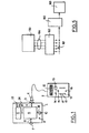
- FIG. 1 there is shown schematically a memory timer 1 according to the invention and an adjustment unit 2, the latter being able to be connected to the timer by means of a connector 3,4.
- the memory timer 1 includes an existing electronics 5 comprising the power supplies, the phase shift circuits, for controlling the water temperature and for closing the electrodes of the welding station. (EV command).
- This existing electronics 5 are associated two potentiometers 23 and 24 as inputs allowing respectively the manual adjustment of the intensity of the welding current and the time of the first docking. These two potentiometers are arranged on the front face of the housing containing the memory timer 1.
- the timer 1 is provided with new electronic elements 6 comprising memories in which one can record using the housing of maintenance 2 the parameters of a welding operation and a memorized weld point counter decremented as they are executed.
- the new electronic elements 6 are connected at 9 by a set of conductors to the connector 3, 4, at 25 to the existing electronics 5, at 8 by a set of conductors at a connector 7 making it possible to connect the memory timer 1 to the station with welding tongs controlled by one or two pedals, and finally at 26 with an electrode change display which flashes for example when a thousand welding spots remain authorized to attract the operator's attention and operates continuously at zero with or without stopping the station.
- a switch 11 makes it possible to connect either in blow-by-blow mode or in on-the-fly mode as regards the operating mode of the station.
- the housing 2 comprises a set of eight coding wheels 12 on which the value of the heel to be entered in the memory of the timer 1 is previously displayed, a set 17, 18, 19 of buttons loading control push buttons, namely: 17: RESET; 18: loading; 19: recording. These three buttons acting, depending on the position of the switch 15, either for inserting the parameters or for entering the number of points or heel.
- the parameters are displayed in 13 stations connected to a display selector 14 with four positions:
- a two-position switch 16 makes it possible to select either on or off.
- the main advantages obtained with the memory timer of the invention are a stability of the parameters displayed and a regularity of the exchange of the electrodes adapted to the part to be welded, therefore ultimately a great improvement in the quality of the welds obtained.
- MOS circuits MN 9 105 from PLESSEY SEMICONDUCTORS comprising a four-decade counter associated with a memory all integrated in the same component. Each decade presents its content on four binary output digits when said output is validated by multiplexing.
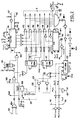
- FIG. 2 illustrates in the memory timer an embodiment of the step counting and the memorization of the settings while FIG. 3 illustrates an embodiment of the solder point counter.
- the memories used MN 9 105 allow a backup long-term data.
- the illustrated embodiment includes a memory of the units 114 and a memory of the tens 113.
- the energy reserve saving the data is constituted by a capacitor on pins 5 and 9.
- a RESET return at zero
- the parameters are entered in series by inputs 107 and 111 in the memories of units 114 and tens 113 in the form of a train of pulses loading the counters of each memory.
- a low level on the input 110 transfers the content of the counters to the memory 113, 114.
- the unit memories 114 and tens 113 are loaded simultaneously.
- the circuit 101 allows the adjustment of the first docking. At rest, the decade containing the value of the approach is present on the memory output.
- On pedal control: P I A 1 at input 103 of circuit 170, monostable 104 type 342 CJ, counts the first approach. At the same time, the contents of the memories are recalled via output 105. After the first docking time, the 50 Hz signal can access the 115,117 counters from input 106.
- the logic gates 118 and 119 with OR function authorize via the logic gate 112 with NAND function, the step-by-step advance and the resetting of the counters.
- the decade representing the soldering time is presented on the pins of the memory output.
- the cycle continues until DEAD TIME when the integrated circuit 122 is again placed in AC (docking) after a RESET on its pin 1 caused by step 4 (Dead time ended).
- EV information is sent to the existing electronics by a conductor 120 causing the electrodes of the welding tongs to open.
- the pedal control by circuit 102 is locked in WELDING and HOLD.
- a fly-by-blow switch connected to the input conductor 121 selects the operating mode and allows, when viewing the settings, to recall the contents of memories 113, 114. Suddenly the DEAD TIME step blocks the command d step by step. The operator must release the pedal, causing a reset allowing another cycle.
- FIG. 3 representing a detailed embodiment of the counter of weld points executed.
- the loading of the heel corresponding to the number of weld points uses the same principle as for the parameters.
- AI recognition of the "welding" step, - the "clock” input requests pin 6 of the counter 130, an operation "minus a” is executed on the contents of the counters, an EV command by the input conductor 132 transmits to the »Dead time « a recording pulse on pin 3.
- the output circuit 134 activates the flashing light 135 for a heel less than a thousand points. When the heel reaches zero, the pin 13 "report" of the counters 130 allows the memorization of this state by a flip-flop 136 of type 7474.
- the inverting output Q of this flip-flop blocks the work station by a RESET, while its output non-inverting Q blocks the recording of zero and controls the permanent lighting of indicator 135.
- Resetting is done by switching off the station. It is necessary to keep "a" in the heel in memory to avoid the overflow of the counters 130 after resetting. Only one weld point can be made after a reset. There is a need to load the new heel if you want to be able to perform a new series of welding operations.
- FIG. 4 illustrates a detailed embodiment of an adjustment box which can be used in association with the memory timer of FIGS. 2 and 3.
- a clock connected to the input conductors 140, 141 changes a series of counters. In parallel, the same number of pulses goes to the memories, 142 to 145 for the units and 146 to 149 for the tens.
- the content of the counters corresponds to the display of codeus wheels, 150 to 153 for the units, 154 to 157 for the tens, the loading is stopped.
- FIG. 4 On the left of FIG. 4 is shown above the case of two seven-segment displays at 13 and below the display selection switch 14 illustrating the case of four positions corresponding to the successive steps: AC; SD; MT and TM.
- the parameters-number of points switch is represented at 16 and at 18 the loading push-button corresponding to the positions 18 in FIG. 1.
- FIG. 5 schematically illustrates an alternative embodiment making it possible to introduce an automatic variation of the welding current.
- a binary / decimal converter 160 On the output conductors 164 of the memory for the number of points included inside the element 130 already appearing in FIG. 3, there is a binary / decimal converter 160 knowing that the counting of the number of points appears in binary code on all four conductors 164.
- a system 161 At the output of the binary / decimal converter 160 there is inserted a system 161 for reading and processing the content of the memory "number of points executed" making it possible to select several values sequentially.
- the output of the system 161 is connected to a flip-flop 162 for memorizing the passage of the heel, itself connected to a system 163 for controlling the intensity of the weld current. In this way the intensity of the welding current can be increased in successive steps, depending on the wear of the electrodes, determined by the number of points executed.
Landscapes
- Engineering & Computer Science (AREA)
- Mechanical Engineering (AREA)
- Arc Welding Control (AREA)
- Lining Or Joining Of Plastics Or The Like (AREA)
Applications Claiming Priority (2)
| Application Number | Priority Date | Filing Date | Title |
|---|---|---|---|
| FR8014789 | 1980-07-03 | ||
| FR8014789A FR2485972A1 (fr) | 1980-07-03 | 1980-07-03 | Temporisateur a memoire, notamment pour poste de soudure |
Publications (2)
| Publication Number | Publication Date |
|---|---|
| EP0043769A1 EP0043769A1 (fr) | 1982-01-13 |
| EP0043769B1 true EP0043769B1 (fr) | 1984-02-01 |
Family
ID=9243797
Family Applications (1)
| Application Number | Title | Priority Date | Filing Date |
|---|---|---|---|
| EP81401064A Expired EP0043769B1 (fr) | 1980-07-03 | 1981-07-02 | Temporisateur à mémoire, notamment pour poste de soudure |
Country Status (3)
| Country | Link |
|---|---|
| EP (1) | EP0043769B1 (enExample) |
| DE (1) | DE3162113D1 (enExample) |
| FR (1) | FR2485972A1 (enExample) |
Families Citing this family (3)
| Publication number | Priority date | Publication date | Assignee | Title |
|---|---|---|---|---|
| IT1143513B (it) * | 1981-02-18 | 1986-10-22 | Comau Spa | Apparecchiatura per il controllo e la programmazione su pinze di saldatura |
| US4456809A (en) * | 1982-03-25 | 1984-06-26 | Pertron Controls Corporation | Microprocessor-controlled controller for resistance welding machines |
| JPH08286725A (ja) * | 1995-04-13 | 1996-11-01 | Miyachi Technos Corp | 抵抗溶接用又はレーザ加工用端末ユニット、抵抗溶接又はレーザ加工制御装置、端末ユニット稼働方法 |
Family Cites Families (6)
| Publication number | Priority date | Publication date | Assignee | Title |
|---|---|---|---|---|
| BE528196A (enExample) * | ||||
| FR1099322A (fr) * | 1953-04-25 | 1955-09-02 | Licentia Gmbh | Disposition de commande électronique |
| FR2331413A1 (fr) * | 1975-11-12 | 1977-06-10 | Beaudoux Jean Claude | Poste de soudage electrique universel |
| BE869621A (fr) * | 1978-08-08 | 1978-12-01 | Centre Rech Metallurgique | Procede pour controler la soudure de produits en acier |
| GB2046475B (en) * | 1979-04-10 | 1983-05-25 | Vnii Str Magistral Truboprovod | Machine for continuous flash butt welding |
| FR2457736A1 (en) * | 1979-05-29 | 1980-12-26 | Inst Po Stroitelstvu Magistral | Flash butt welding machine - with sensors for all parameters affecting weld quality (OE 15.6.80) |
-
1980
- 1980-07-03 FR FR8014789A patent/FR2485972A1/fr active Granted
-
1981
- 1981-07-02 EP EP81401064A patent/EP0043769B1/fr not_active Expired
- 1981-07-02 DE DE8181401064T patent/DE3162113D1/de not_active Expired
Non-Patent Citations (1)
| Title |
|---|
| IEEE TRANSACTIONS ON INDUSTRIAL ELECTRONICS AND CONTROL INSTRUMENTATION, vol. IECI-25, no. 1, février 1978 NEW YORK (US) J.A. HEISEL et al.: "Microcomputer-controlled resistance welder" pages 14-16 * |
Also Published As
| Publication number | Publication date |
|---|---|
| FR2485972A1 (fr) | 1982-01-08 |
| DE3162113D1 (en) | 1984-03-08 |
| FR2485972B1 (enExample) | 1984-10-26 |
| EP0043769A1 (fr) | 1982-01-13 |
Similar Documents
| Publication | Publication Date | Title |
|---|---|---|
| FR2523886A1 (fr) | Controleur commande par microprocesseur pour machines de soudage par resistance | |
| DE3333552A1 (de) | Steuerungseinrichtung fuer einen verkaufsautomaten | |
| EP0043769B1 (fr) | Temporisateur à mémoire, notamment pour poste de soudure | |
| WO1990014850A1 (fr) | Gestion de parametres relatifs a un traitement de dialyse | |
| FR2605415A1 (fr) | Appareil de controle de l'etat de charge d'une pile | |
| FR2638565A1 (fr) | Declencheur a microprocesseur a fonctions optionnelles et procede de selection desdites fonctions | |
| DE3152272C1 (de) | Einrichtung zum Berechnen und Anzeigen der Werte von Belichtungsparametern fuer photographische Aufnahmen | |
| FR2501184A1 (fr) | Dispositif de traitement de l'eau par impulsions electriques a gradation de puissance | |
| FR2554928A1 (fr) | Wattheuremetre | |
| FR2618562A1 (fr) | Procede pour le controle de facon continue et automatique du fonctionnement electrique et de la conformite de la commande dans une unite d'affichage a cristaux liquides | |
| DE2804662C2 (de) | Steuerschaltung für einen Münzfernsprecher | |
| EP0042649A1 (de) | Dienstleistungsanordnung mit einer digitalen Programmieranordnung die gegen Störungen durch beliebiges Einschalten des Geräts gesichert ist | |
| FR2547074A1 (fr) | Minuteur electronique | |
| EP0156716B1 (fr) | Appareil de cuisson à commande interactive | |
| FR2499891A1 (fr) | Appareillage pour le controle et la programmation de pinces de soudure | |
| EP0046110A1 (fr) | Dispositif d'obtention de l'histogramme des distances dans le temps entre des événements successifs | |
| DE3501187A1 (de) | Gewinn-in-aussicht-stellender spielautomat | |
| FR2709993A1 (fr) | Dispositif perfectionné pour contrôle de soudure. | |
| FR2665559A1 (fr) | Systeme de gestion de vehicules electriques a batterie d'accumulateurs, boitier de vehicule et boitier de batterie d'un tel systeme, et vehicule comprenant un tel boitier de vehicule. | |
| DE2717763C2 (de) | Automatisches Belichtungssteuersystem sowie Blitzlichtgerät | |
| EP1749494B1 (fr) | Appareil de traitement par émission de flashs lumineux, notamment d'épilation | |
| FR2499258A1 (fr) | Appareil electronique utilisable comme horloge numerique ou chronographe | |
| FR2535088A1 (fr) | Procede et dispositifs pour limiter l'activite quotidienne d'un chauffeur de taxi | |
| CH621027B5 (enExample) | ||
| FR2599466A1 (fr) | Commande electronique d'installation de graissage centralisee, en particulier pour vehicules |
Legal Events
| Date | Code | Title | Description |
|---|---|---|---|
| PUAI | Public reference made under article 153(3) epc to a published international application that has entered the european phase |
Free format text: ORIGINAL CODE: 0009012 |
|
| AK | Designated contracting states |
Designated state(s): BE CH DE GB IT SE |
|
| 17P | Request for examination filed |
Effective date: 19811111 |
|
| ITF | It: translation for a ep patent filed | ||
| GRAA | (expected) grant |
Free format text: ORIGINAL CODE: 0009210 |
|
| AK | Designated contracting states |
Designated state(s): BE CH DE GB IT LI SE |
|
| REF | Corresponds to: |
Ref document number: 3162113 Country of ref document: DE Date of ref document: 19840308 |
|
| PGFP | Annual fee paid to national office [announced via postgrant information from national office to epo] |
Ref country code: DE Payment date: 19840618 Year of fee payment: 4 |
|
| PGFP | Annual fee paid to national office [announced via postgrant information from national office to epo] |
Ref country code: SE Payment date: 19840630 Year of fee payment: 4 Ref country code: BE Payment date: 19840630 Year of fee payment: 4 |
|
| PGFP | Annual fee paid to national office [announced via postgrant information from national office to epo] |
Ref country code: CH Payment date: 19840808 Year of fee payment: 4 |
|
| PLBI | Opposition filed |
Free format text: ORIGINAL CODE: 0009260 |
|
| 26 | Opposition filed |
Opponent name: ROBERT BOSCH GMBH, STUTTGART Effective date: 19841025 |
|
| RDAG | Patent revoked |
Free format text: ORIGINAL CODE: 0009271 |
|
| STAA | Information on the status of an ep patent application or granted ep patent |
Free format text: STATUS: PATENT REVOKED |
|
| 27W | Patent revoked |
Effective date: 19870201 |
|
| REG | Reference to a national code |
Ref country code: CH Ref legal event code: PL |
|
| GBPR | Gb: patent revoked under art. 102 of the ep convention designating the uk as contracting state | ||
| BERE | Be: lapsed |
Owner name: REGIE NATIONALE DES USINES RENAULT Effective date: 19870731 |
|
| EUG | Se: european patent has lapsed |
Ref document number: 81401064.1 Effective date: 19880901 |