EP0043764B1 - Schubumkehrvorrichtung für ein Strahltriebwerk für Flugzeuge - Google Patents
Schubumkehrvorrichtung für ein Strahltriebwerk für Flugzeuge Download PDFInfo
- Publication number
- EP0043764B1 EP0043764B1 EP81401059A EP81401059A EP0043764B1 EP 0043764 B1 EP0043764 B1 EP 0043764B1 EP 81401059 A EP81401059 A EP 81401059A EP 81401059 A EP81401059 A EP 81401059A EP 0043764 B1 EP0043764 B1 EP 0043764B1
- Authority
- EP
- European Patent Office
- Prior art keywords
- door
- doors
- thrust reverser
- section
- upstream
- Prior art date
- Legal status (The legal status is an assumption and is not a legal conclusion. Google has not performed a legal analysis and makes no representation as to the accuracy of the status listed.)
- Expired
Links
Images


Classifications
-
- F—MECHANICAL ENGINEERING; LIGHTING; HEATING; WEAPONS; BLASTING
- F02—COMBUSTION ENGINES; HOT-GAS OR COMBUSTION-PRODUCT ENGINE PLANTS
- F02K—JET-PROPULSION PLANTS
- F02K1/00—Plants characterised by the form or arrangement of the jet pipe or nozzle; Jet pipes or nozzles peculiar thereto
- F02K1/54—Nozzles having means for reversing jet thrust
- F02K1/56—Reversing jet main flow
- F02K1/563—Reversing jet main flow in specified direction, e.g. to obviate its reinjection
-
- F—MECHANICAL ENGINEERING; LIGHTING; HEATING; WEAPONS; BLASTING
- F02—COMBUSTION ENGINES; HOT-GAS OR COMBUSTION-PRODUCT ENGINE PLANTS
- F02K—JET-PROPULSION PLANTS
- F02K1/00—Plants characterised by the form or arrangement of the jet pipe or nozzle; Jet pipes or nozzles peculiar thereto
- F02K1/54—Nozzles having means for reversing jet thrust
- F02K1/64—Reversing fan flow
- F02K1/70—Reversing fan flow using thrust reverser flaps or doors mounted on the fan housing
- F02K1/72—Reversing fan flow using thrust reverser flaps or doors mounted on the fan housing the aft end of the fan housing being movable to uncover openings in the fan housing for the reversed flow
Definitions
- the present invention relates to a thrust reverser for a jet engine with an external cowling surrounding a motor structure and delimiting therewith an annular channel for the flow of a gas flow from an upstream region to a downstream region, the inversion thrust being produced by doors capable of tilting from an inactive position to an inclined position of reverse thrust in which they extend transversely to the annular channel which they close, while freeing a passage in the cowling, allowing the flow to be deflected radially outwards from the annular channel and upstream, these doors being coupled by external connecting rods to a downstream section of cowling which is capable of moving, under the action of control members, axially with respect to the structure of the engine.
- the doors constitute a structure which is added to that of the external cowling of the engine; in the inactive position, they are located inside this casing, which results in a complication and an increase in weight.
- the door control members namely the jacks
- the door control members do not act directly on the movable downstream section of the cowling; they cause the latter to retreat only by means of the doors themselves and the connecting rods, which subjects the connecting rods to bending forces; therefore, the doors themselves are subjected to the efforts of the cylinders.
- the cylinders are mounted between the fixed structure and a central zone of the doors, which also contributes to subjecting them to forces which risk deforming them and places the cylinders in the hot flow d 'reverse thrust, which is a major drawback of the system.
- the object of the present invention is to obtain a thrust reverser of the general type of that mentioned at the start, but which does not have the aforementioned drawbacks.
- a thrust reverser of the type in question will, in accordance with the present invention, be essentially characterized in that said doors constitute elements of an intermediate section of the cowling situated between a fixed upstream section and the movable downstream section of that -ci, and, in the inactive position, are in the alignment of these upstream and downstream sections; in that these doors are pivotally mounted each on a fixed axis integral with the upstream fixed section; and in that said control members extend directly between said upstream fixed section and the downstream movable section, laterally with respect to said doors, so, on the one hand, that their actuation causes a retraction of said movable section and, consequently, a tilting of the doors in the thrust reversal position, only by means of a traction exerted by said movable section on said connecting rods, and on the other hand that they are located outside the thrust reversal flow.
- control members (the jacks) extend directly between the upstream fixed section and the downstream movable section, laterally with respect to the doors, makes it possible to obtain the following two important results: actuation cylinders causes a retraction of the movable section of the cowling and consequently a tilting of the doors in the thrust reversal position only by means of a traction exerted by the movable section on the connecting rods, and, moreover, the cylinders are outside the hot reverse thrust flow.
- each door extends on either side of its articulation to beams integral with the upstream section and receiving said control members.
- each door link is articulated on the one hand at the upstream edge of the downstream movable section and on the other hand at the corresponding door in a zone situated between the upstream edge of the door and the articulation zone from the door to the supporting beams.
- each of the doors is located between two adjacent beams and it is articulated to each of these doors by a lateral articulation pivot; in addition, each door is equipped with a single actuating rod which is placed between the articulation pivots of the door.
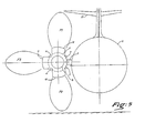
- the inverter structure proposed above can in particular be adapted to the case of an aircraft engine in the "lateral nacelle" configuration in which the engine is fixed by a mast to the carrying structure.
- the reverser will consist of three doors, one of which is approximately diametrically opposite the mast and the other two are located approximately symmetrically with respect to a horizontal plane passing through the axis of the engine.
- the doors are carried by four beams which can each form part of the wall of the cowling.
- the rear part of each door has, in plan, a concave configuration with, in the vicinity of the hinge pivots of the door, two lateral horns extending towards the rear and a narrowed middle part, the curvilinear rear edge of the door conforming to the shape of the central body of the motor when the door is in the inversion position.
- the front edge of the downstream mobile section will have a configuration corresponding to the configuration of the curvilinear rear edges of the doors, so that in the retracted door position, said rear edges of the doors fit into the front edge of the movable section, thus cooperating in the action of the jacks ensuring the maintenance of the doors in the closed position.
- the inverter structure described above can find an advantageous application in the case of motors in which a primary flow flow (hot) and a secondary flow flow (cold) are produced by to a front fan (or fan), these two flows being ejected through the single annular channel reserved between the central body and the cowling, the inverter of the invention in this case ensures practically the derivation of all the flows created by the engine and blower.
- the simplicity and the robustness of the inverter of the invention are particularly suitable for such a case because no fragile member (control jack or articulation pivot) is in contact with the bypass stream which is at a high temperature.
- the engine 3 is conventionally fixed to the fuselage 1 of the aircraft by a nacelle mast 2, the engine being surrounded by a tubular casing generally designated at 4.
- a front fan or blower 5 is associated with the reactor which in the example shown is of a particular type in which the rear forms a closed central body 3a, bulky and of great length in which the high pressure turbine, the chamber are housed combustion and all engine equipment.
- the hot primary flow is ejected by peripheral nozzles 3b opening in the annular channel CA reserved between the external wall of the engine 3 and the cowling 4 and which also serves for the flow of the secondary flow coming from the fan.
- the cowling 4 consists of three sections, namely a fixed upstream section 4a which surrounds the fan and the front of the motor, a downstream section 4b, or ferrule, which is movable in axial translation and an intermediate section 4c consisting of tilting doors forming the deflector mechanism.
- the two beams 7 are located on either side of the nacelle mast 2, while the two beams 6 are distributed opposite.
- each of the beams is housed a jack V, the free end of the rod 8 of which is articulated at 9 on the front structure 10 of the movable shell 4b, the movement of the cylinders ensuring the displacement of the shell along the longitudinal axis XX ' of the motor.
- said ferrule 4b has a substantially C section, its free edges being engaged in longitudinal slides (not shown) formed in the fixed structure of the nacelle mast and allowing the ferrule to be guided during its movement.
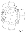
- Each door 11-12 and 13 is articulated by two lateral pivots 14 on two adjacent beams, the door 11 being articulated between the two beams 6 and the doors 12 and 13 respectively between a beam 7 and a beam 6 (see FIG. 3).
- the two pivots of each door are aligned on the same geometric axis and all the geometric axes of articulation of the doors are located in the same plane normal to the axis X-X "of the motor.
- pivots 14 are located at immediate vicinity of the rear end of the beams 67.
- Each door is also coupled to the movable ferrule 4b by a connecting rod 15 disposed in a radial plane of the motor and in the central region of the door.
- This connecting rod 15 is articulated at 16 in ears 23 secured to the external face of the door and at 17 on ears 35 provided on the front structure of the edge 10 before the ferrule.
- the articulation axis 16 of the connecting rod is located between the upstream edge of the door and the articulation pivots 14 of the door to the support beams.
- the rods 15 projecting outwards, it is possible, for aerodynamic reasons, to cover them with a fairing formed of shells 01, 02 and 03, the shell 01 being fixed on the door , the shell 03 on the connecting rod and the shell 02 on the ferrule 4b, The shells are free relative to each other to allow their relative displacement during the movement of the doors and the ferrule.
- the door has a curved outer wall 20 in the rear part of which are fixed folded sheet metal frames 22 and 24 in a U shape which provide rigidity at the rear edge of the door.
- a fitting 25 which, in the retracted door position (FIG. 4), is located under the articulation 17 of the connecting rod to the ferrule 4b and comes to crush a seal 36 fixed on the face front 10 of the ferrule, this seal 36 ensuring the sealing of the rear of the door.
- an internal wall 26 Inside the frames 22 and 24 is fixed an internal wall 26 whose rear end covers the fitting 25 to which it is fixed at 30.
- the internal wall 26 is fixed, at the front of the door, against the wall external 20 by means of a front frame 27 projecting towards the inside of the door and constituting a spoiler ensuring an additional deflection of the diverted flow when the door is open.
- the front of the door is sealed in the retracted position by means of a seal 28 fixed to the front of an internal wall PI secured to the fixed section 4a and extending it downstream, the seal 28 being crushed by the internal wall 26 of the door when the latter is retracted.
- the position of the seal 28 prevents any leakage of the flow towards the front of the doors when they are retracted.
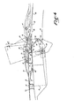
- the arrangement of the door is preferably such that in the retracted position, the plane of the pivots 14 of articulation of the doors to the beams is located between the axes 16 and 17 of articulation of the connecting rods at the door and the ferrule. Furthermore, the articulation point 16 of the connecting rod to the door is located at a distance from the downstream edge of the door such that, when the door is in the thrust reversal position shown in broken lines in FIG. 4, the articulation point 16 is located substantially at the same distance from the axis of the engine as the articulation point 17 of the connecting rod to the ferrule 4b.
- the trajectory of the axis 16 has been shown in T and it can be seen that this trajectory deviates very little from the generatrix of the cowling, which means that the connecting rods 15 will always be, during operation, in an almost horizontal position .
- each of the doors extends on either side of the articulation zone 14 to the beams.
- G more particularly the rear part of the doors which must ensure the obturation of the annular channel between engine and cowling during the thrust reversal.
- the rear part of the door has a substantially crescent shape with a curvilinear end edge 31 matching the shape of a fraction of the external wall of the motor.
- This rear part comprises, in the vicinity of the articulation pivots 14, two lateral horns 32 extending rearwards in the retracted door position, and a narrowed central part 32 '.
- the distance "1" measured between the lateral horns is less than the width L of the door, said horns being connected to the parallel lateral edges 34 of the door by parts 33 converging towards the axis of the door.
- the parts 33 of the adjacent doors come opposite one another under the beams 6 in order to achieve optimum sealing of the annular channel.
- the front edge of the wall 38 is cut to present a configuration corresponding to the configuration of the curved rear edges 31-32 of the doors.
- the edge of the wall 38 has a serrated shape 39 ⁇ 40 in which fits the rear of the door in the retracted door position shown in Figure 3. This interlocking of complementary shapes of the edges 31-32 and 39 ⁇ 40 cooperate in maintaining the doors in the closed position.
- the operation of the inverter is very simple.
- the actuating cylinders of the ferrule are retracted and the ferrule occupies the position in solid line in FIGS. 1 and 4.
- the three doors are folded down in the retracted position and the continuous internal wall of the cowling is constituted by an internal wall.
- PI extending the fixed section 4a beyond the junction plane between 4a and 4c, by the wall 26 of the doors and through the wall 38 of the shell.
- the ferrule cylinders are actuated which push it backwards.
- the connecting rods 15 then cause the doors to tilt and open, in the position indicated in broken lines, that is to say with an inclination "a" upstream relative to a vertical plane.
- Passages PA of substantially rectangular shape are then formed between the doors and the edge of the extension Pl, passages through which the primary and secondary flows are derived towards the outside and upstream.
- the three doors of the inverter burst the flow into three layers F i , F 2 and F 3 . Since a third of the flow is discharged through the door 11 laterally outwards, the size of the sheet F (deflected upwards in the vicinity of the directional structures D of the device located at the rear) as well as the size of the sheet F 2 (deflected towards the ground and capable of creating unfavorable interactions between the ground and the fuselage 1) is reduced accordingly, which significantly reduces the drawbacks linked to the arrangement of the sheets F, and F 2 .
Claims (15)
Applications Claiming Priority (2)
| Application Number | Priority Date | Filing Date | Title |
|---|---|---|---|
| FR8014907 | 1980-07-04 | ||
| FR8014907A FR2486153B1 (fr) | 1980-07-04 | 1980-07-04 | Inverseur de poussee pour moteur a reaction, destine notamment a equiper un aeronef |
Publications (2)
| Publication Number | Publication Date |
|---|---|
| EP0043764A1 EP0043764A1 (de) | 1982-01-13 |
| EP0043764B1 true EP0043764B1 (de) | 1985-05-02 |
Family
ID=9243853
Family Applications (1)
| Application Number | Title | Priority Date | Filing Date |
|---|---|---|---|
| EP81401059A Expired EP0043764B1 (de) | 1980-07-04 | 1981-07-01 | Schubumkehrvorrichtung für ein Strahltriebwerk für Flugzeuge |
Country Status (4)
| Country | Link |
|---|---|
| US (1) | US4410152A (de) |
| EP (1) | EP0043764B1 (de) |
| DE (1) | DE3170269D1 (de) |
| FR (1) | FR2486153B1 (de) |
Cited By (1)
| Publication number | Priority date | Publication date | Assignee | Title |
|---|---|---|---|---|
| EP4350140A1 (de) * | 2022-10-07 | 2024-04-10 | Rohr, Inc. | Schubumkehrsystem mit abgewinkelten türschwenkachsen |
Families Citing this family (47)
| Publication number | Priority date | Publication date | Assignee | Title |
|---|---|---|---|---|
| FR2506843B1 (fr) * | 1981-05-29 | 1987-04-24 | Hurel Dubois Avions | Dispositif d'inversion de poussee pour turboreacteur d'avion |
| FR2611233B1 (fr) * | 1987-02-19 | 1991-05-10 | Hurel Dubois Avions | Groupe moto-propulseur d'avion du type a ventilateur capote equipe d'un inverseur de poussee a portes |
| FR2618853B1 (fr) * | 1987-07-29 | 1989-11-10 | Hispano Suiza Sa | Inverseur de poussee de turboreacteur muni d'un deflecteur mobile de porte |
| FR2618852B1 (fr) * | 1987-07-29 | 1989-11-10 | Hispano Suiza Sa | Inverseur de poussee de turboreacteur muni d'un dispositif redresseur de flux |
| FR2621082A1 (fr) * | 1987-09-30 | 1989-03-31 | Hispano Suiza Sa | Inverseur de poussee de turboreacteur a portes munies d'une plaque au profil de veine |
| FR2627807B1 (fr) * | 1988-02-25 | 1990-06-29 | Hispano Suiza Sa | Inverseur de poussee de turboreacteur a double flux equipe de bords de deviation munis de levres mobiles |
| FR2634251B1 (fr) * | 1988-07-18 | 1993-08-13 | Hispano Suiza Sa | Inverseur de poussee de turboreacteur a double flux equipe de bords de deviation mobiles |
| FR2638207B1 (fr) * | 1988-10-20 | 1990-11-30 | Hispano Suiza Sa | Inverseur de poussee de turboreacteur, a portes pivotantes equilibrees |
| US5039171A (en) * | 1989-08-18 | 1991-08-13 | Societe Anonyme Dite Hispano-Suiza | Multi-panel thrust reverser door |
| FR2651278B1 (fr) * | 1989-08-23 | 1994-05-06 | Hispano Suiza | Inverseur a grilles sans capot coulissant pour turboreacteur. |
| US5203164A (en) * | 1990-06-06 | 1993-04-20 | Paulson Allen E | Method and apparatus for quieting a turbojet engine |
| FR2669079B1 (fr) * | 1990-11-14 | 1994-12-30 | Hurel Dubois Avions | Amelioration aux inverseurs de poussee a portes pour avion a reaction. |
| GB2252279A (en) * | 1991-02-01 | 1992-08-05 | Rolls Royce Plc | Thrust reverser |
| US5197693A (en) * | 1991-08-15 | 1993-03-30 | Rohr, Inc. | Aircraft turbine engine thrust reverser with sliding hinge actuator |
| FR2680547B1 (fr) * | 1991-08-21 | 1993-10-15 | Hispano Suiza | Inverseur de poussee de turboreacteur ayant un bord de deviation a courbure evolutive. |
| FR2681101B1 (fr) * | 1991-09-11 | 1993-11-26 | Hispano Suiza | Inverseur de poussee de turboreacteur a pilotage ameliore des nappes du flux inverse. |
| FR2730763B1 (fr) * | 1995-02-21 | 1997-03-14 | Hispano Suiza Sa | Inverseur de poussee a volets aval pour turboreacteur |
| FR2736682B1 (fr) * | 1995-07-12 | 1997-08-14 | Hispano Suiza Sa | Inverseur de poussee de turbomachine a double flux a portes dissymetriques |
| US5730392A (en) * | 1995-09-22 | 1998-03-24 | Aeronautical Concept Of Exhaust, Ltd. | Adjustable fairing for thrust reversers |
| FR2742482B1 (fr) * | 1995-12-19 | 1998-02-06 | Hurel Dubois Avions | Inverseur de poussee a tuyere a section reglable pour moteur d'avion a reaction |
| DE69616739T2 (de) * | 1996-02-08 | 2002-09-05 | Hurel Dubois Avions | Dichtungsanordnung für schwenkbare Schubumkehrklappe |
| EP0852290A1 (de) | 1996-12-19 | 1998-07-08 | SOCIETE DE CONSTRUCTION DES AVIONS HUREL-DUBOIS (société anonyme) | Schubumkehrvorrichtung für ein Bläsertriebwerk |
| FR2768773B1 (fr) * | 1997-09-25 | 1999-11-05 | Hispano Suiza Sa | Inverseur de poussee de turboreacteur a coquilles internes |
| US6311928B1 (en) * | 2000-01-05 | 2001-11-06 | Stage Iii Technologies, L.C. | Jet engine cascade thrust reverser for use with mixer/ejector noise suppressor |
| DE60021585D1 (de) * | 2000-12-18 | 2005-09-01 | Techspace Aero Sa | Prüfstand für Schubumkehr |
| US6938408B2 (en) * | 2001-04-26 | 2005-09-06 | Propulsion Vectoring, L.P. | Thrust vectoring and variable exhaust area for jet engine nozzle |
| FR2962977B1 (fr) * | 2010-07-20 | 2012-08-17 | Airbus Operations Sas | Nacelle pour aeronef |
| US9617009B2 (en) | 2013-02-22 | 2017-04-11 | United Technologies Corporation | ATR full ring sliding nacelle |
| US9435293B2 (en) | 2013-02-22 | 2016-09-06 | United Technologies Corporation | Full ring sliding nacelle with thrust reverser |
| US9631578B2 (en) | 2013-02-22 | 2017-04-25 | United Technologies Corporation | Pivot thrust reverser surrounding inner surface of bypass duct |
| US9447749B2 (en) * | 2013-04-02 | 2016-09-20 | Rohr, Inc. | Pivoting blocker door for thrust reverser |
| FR3016863B1 (fr) * | 2014-01-29 | 2017-05-26 | Snecma | Nacelle pour turboreacteur d'avion |
| US10344709B2 (en) * | 2015-09-10 | 2019-07-09 | Honeywell International Inc. | System and method for reducing idle thrust in a translating cowl thrust reverser |
| FR3057617B1 (fr) * | 2016-10-17 | 2020-10-16 | Airbus | Nacelle d'un turboreacteur comportant un volet inverseur |
| FR3060660B1 (fr) * | 2016-12-20 | 2019-05-17 | Safran Nacelles | Nacelle de turboreacteur d'aeronef, ensemble propulsif et aeronef comportant une telle nacelle |
| FR3062371B1 (fr) * | 2017-01-31 | 2019-03-29 | Airbus | Nacelle d'un turboreacteur comportant un volet inverseur |
| RU2663249C1 (ru) | 2017-03-16 | 2018-08-03 | Акционерное общество "Объединенная двигателестроительная корпорация" (АО "ОДК") | Способ изготовления секций несущей решетки реверсера тяги |
| FR3064686B1 (fr) * | 2017-03-30 | 2019-04-19 | Airbus Operations | Nacelle d'un turboreacteur comportant un volet inverseur |
| FR3066232B1 (fr) * | 2017-05-15 | 2019-05-03 | Airbus | Nacelle d'un turboreacteur comportant un volet inverseur |
| US10865737B2 (en) * | 2017-08-29 | 2020-12-15 | Honeywell International Inc. | Hidden linkage for a translating cowl thrust reverser |
| US10724474B2 (en) | 2018-05-01 | 2020-07-28 | Rohr, Inc. | Hybrid articulating/translating trailing edge reverser |
| US10830177B2 (en) | 2018-05-01 | 2020-11-10 | Rohr, Inc. | Articulating pivot point post-exit thrust reverser |
| US11053887B2 (en) | 2018-07-02 | 2021-07-06 | Rohr, Inc. | Thrust reverser with displaceable trailing edge body |
| US11187187B2 (en) | 2018-08-06 | 2021-11-30 | Rohr, Inc. | Thrust reverser |
| FR3099221B1 (fr) * | 2019-07-22 | 2022-08-26 | Safran Nacelles | Joint d’étanchéité pour aéronef |
| FR3111952B1 (fr) * | 2020-06-25 | 2022-08-26 | Safran Nacelles | Inverseur de poussée à trois portes |
| FR3122219B1 (fr) | 2021-04-21 | 2023-07-14 | Safran Nacelles | Inverseur de poussée comprenant des portes basculantes et une virole arrière coulissante |
Family Cites Families (19)
| Publication number | Priority date | Publication date | Assignee | Title |
|---|---|---|---|---|
| GB812167A (en) * | 1956-04-17 | 1959-04-22 | Rolls Royce | Improvements in or relating to jet nozzles for jet-propulsion purposes |
| US3050937A (en) * | 1958-06-09 | 1962-08-28 | Boeing Co | Reversible thrust jet engines and controls therefor |
| US3036431A (en) * | 1959-09-08 | 1962-05-29 | Boeing Co | Thrust reverser for jet engines |
| US3097484A (en) * | 1960-06-13 | 1963-07-16 | Thrust reversers for jet engines | |
| GB1052963A (de) * | 1963-09-30 | |||
| US3279182A (en) * | 1965-06-07 | 1966-10-18 | Gen Electric | Thrust reverser |
| FR1482538A (fr) * | 1965-06-07 | 1967-05-26 | Gen Electric | Inverseur de poussée |
| GB1130268A (en) * | 1967-07-01 | 1968-10-16 | Rolls Royce | Improvements in or relating to gas turbine by-pass engines |
| GB1177864A (en) * | 1968-04-09 | 1970-01-14 | Rolls Royce | Thrust Reverser or Spoiler |
| US3612401A (en) * | 1970-01-29 | 1971-10-12 | Rohr Corp | Thrust-reversing apparatus for turbofan jet engine |
| US3599874A (en) * | 1970-03-23 | 1971-08-17 | Rohr Corp | Thrust-reversing apparatus |
| US3665709A (en) * | 1970-06-04 | 1972-05-30 | Rohr Corp | Thrust reversing apparatus |
| US3601992A (en) * | 1970-06-10 | 1971-08-31 | Rohr Corp | Thrust reversing apparatus |
| US3605411A (en) * | 1970-07-01 | 1971-09-20 | Rohr Corp | Thrust reversing apparatus |
| US3684183A (en) * | 1970-09-16 | 1972-08-15 | Rohr Corp | Thrust controlling apparatus |
| US3699682A (en) * | 1971-01-04 | 1972-10-24 | Mc Donnell Douglas Corp | Turbofan engine thrust reverser |
| US3815357A (en) * | 1971-01-28 | 1974-06-11 | Rohr Industries Inc | Thrust reversing apparatus |
| US4073440A (en) * | 1976-04-29 | 1978-02-14 | The Boeing Company | Combination primary and fan air thrust reversal control systems for long duct fan jet engines |
| GB1534583A (en) * | 1976-06-08 | 1978-12-06 | Short Bros Ltd | Reversal of thrust in gas turbine engines |
-
1980
- 1980-07-04 FR FR8014907A patent/FR2486153B1/fr not_active Expired
-
1981
- 1981-07-01 US US06/279,238 patent/US4410152A/en not_active Expired - Lifetime
- 1981-07-01 EP EP81401059A patent/EP0043764B1/de not_active Expired
- 1981-07-01 DE DE8181401059T patent/DE3170269D1/de not_active Expired
Cited By (1)
| Publication number | Priority date | Publication date | Assignee | Title |
|---|---|---|---|---|
| EP4350140A1 (de) * | 2022-10-07 | 2024-04-10 | Rohr, Inc. | Schubumkehrsystem mit abgewinkelten türschwenkachsen |
Also Published As
| Publication number | Publication date |
|---|---|
| DE3170269D1 (en) | 1985-06-05 |
| FR2486153B1 (fr) | 1985-10-04 |
| US4410152A (en) | 1983-10-18 |
| EP0043764A1 (de) | 1982-01-13 |
| FR2486153A1 (fr) | 1982-01-08 |
Similar Documents
| Publication | Publication Date | Title |
|---|---|---|
| EP0043764B1 (de) | Schubumkehrvorrichtung für ein Strahltriebwerk für Flugzeuge | |
| CA1329487C (fr) | Inverseur de poussee de turboreacteur, a portes pivotantes equilibrees | |
| EP0067747B1 (de) | Schuhumkehrvorrichtung für einen Strahlmotor | |
| EP0281455B1 (de) | Strahltriebwerk mit Schubumkehrvorrichtung | |
| EP0757170B1 (de) | Schubumkehrvorrichtung für ein Strahltriebwerk, mit einer Klappe | |
| EP2268910A2 (de) | Bypassgasturbinengondel | |
| FR2711733A1 (fr) | Inverseur de poussée à portes pour moteur d'avion à réaction équipées d'un volet auxiliaire. | |
| WO2010061107A1 (fr) | Inverseur de poussee pour nacelle de turboreacteur a double flux | |
| EP2509870B1 (de) | Hintere inspektionsklappen eines triebwerkes | |
| CA2243099C (fr) | Inverseur de poussee de turbosoufflante a obstacles a guidage axial lies au capot primaire | |
| WO1996038661A1 (fr) | Ensemble d'inverseur de poussee a deux portes | |
| WO1999051870A1 (fr) | Inverseur de poussee de turboreacteur a portes formant ecopes associees a un capotage externe articule | |
| EP0692619B1 (de) | Schubumkehrvorrichtung für ein Zweikreistriebwerk mit externen Klappen | |
| WO2008139048A2 (fr) | Nacelle pour turboreacteur equipee d'un systeme d'inversion de poussee a une seule porte | |
| WO1998055755A1 (fr) | Inverseur de poussee de turboreacteur a portes formant ecopes associees a un deflecteur mobile | |
| FR2966882A1 (fr) | Inverseur de poussee pour turboreacteur d'aeronef a nombre d'actionneurs reduit | |
| FR2764340A1 (fr) | Inverseur de poussee de turboreacteur a portes munies d'un becquet mobile a entrainement optimise | |
| EP0764779A1 (de) | Schubumkehrvorrichtung mit einem mit Primärteil verbundenen Klappen | |
| FR2602274A1 (fr) | Tuyere de reacteur convergente-divergente a section reglable | |
| EP0859142B1 (de) | Schubumkehrvorrichtung für Turbonantriebwerk mit hohem Nebenstromverhältnis | |
| EP0362051B1 (de) | Zweidimensionale Strahltriebsdüse und deren Kontrollsystem | |
| FR2927956A1 (fr) | Inverseur de poussee pour nacelle de turboreacteur a double flux | |
| FR2724977A1 (fr) | Tuyere convergente-divergente en particulier pour turboreacteur | |
| FR2625261A1 (fr) | Inverseur de poussee de turboreacteur a obstacles lies au capot primaire | |
| EP0131079A1 (de) | Schubumkehrvorrichtung mit Klappe speziell für Flugzeugstrahltriebwerke |
Legal Events
| Date | Code | Title | Description |
|---|---|---|---|
| PUAI | Public reference made under article 153(3) epc to a published international application that has entered the european phase |
Free format text: ORIGINAL CODE: 0009012 |
|
| AK | Designated contracting states |
Designated state(s): DE GB NL |
|
| 17P | Request for examination filed |
Effective date: 19811205 |
|
| GRAA | (expected) grant |
Free format text: ORIGINAL CODE: 0009210 |
|
| AK | Designated contracting states |
Designated state(s): DE GB NL |
|
| REF | Corresponds to: |
Ref document number: 3170269 Country of ref document: DE Date of ref document: 19850605 |
|
| PLBE | No opposition filed within time limit |
Free format text: ORIGINAL CODE: 0009261 |
|
| STAA | Information on the status of an ep patent application or granted ep patent |
Free format text: STATUS: NO OPPOSITION FILED WITHIN TIME LIMIT |
|
| 26N | No opposition filed | ||
| PGFP | Annual fee paid to national office [announced via postgrant information from national office to epo] |
Ref country code: GB Payment date: 19990720 Year of fee payment: 19 |
|
| PGFP | Annual fee paid to national office [announced via postgrant information from national office to epo] |
Ref country code: NL Payment date: 19990730 Year of fee payment: 19 Ref country code: DE Payment date: 19990730 Year of fee payment: 19 |
|
| PG25 | Lapsed in a contracting state [announced via postgrant information from national office to epo] |
Ref country code: GB Free format text: LAPSE BECAUSE OF NON-PAYMENT OF DUE FEES Effective date: 20000701 |
|
| PG25 | Lapsed in a contracting state [announced via postgrant information from national office to epo] |
Ref country code: NL Free format text: LAPSE BECAUSE OF NON-PAYMENT OF DUE FEES Effective date: 20010201 |
|
| GBPC | Gb: european patent ceased through non-payment of renewal fee |
Effective date: 20000701 |
|
| NLV4 | Nl: lapsed or anulled due to non-payment of the annual fee |
Effective date: 20010201 |
|
| PG25 | Lapsed in a contracting state [announced via postgrant information from national office to epo] |
Ref country code: DE Free format text: LAPSE BECAUSE OF NON-PAYMENT OF DUE FEES Effective date: 20010501 |