EP0043764B1 - Thrust reverser for an aircraft jet engine - Google Patents
Thrust reverser for an aircraft jet engine Download PDFInfo
- Publication number
- EP0043764B1 EP0043764B1 EP81401059A EP81401059A EP0043764B1 EP 0043764 B1 EP0043764 B1 EP 0043764B1 EP 81401059 A EP81401059 A EP 81401059A EP 81401059 A EP81401059 A EP 81401059A EP 0043764 B1 EP0043764 B1 EP 0043764B1
- Authority
- EP
- European Patent Office
- Prior art keywords
- door
- doors
- thrust reverser
- section
- upstream
- Prior art date
- Legal status (The legal status is an assumption and is not a legal conclusion. Google has not performed a legal analysis and makes no representation as to the accuracy of the status listed.)
- Expired
Links
Images


Classifications
-
- F—MECHANICAL ENGINEERING; LIGHTING; HEATING; WEAPONS; BLASTING
- F02—COMBUSTION ENGINES; HOT-GAS OR COMBUSTION-PRODUCT ENGINE PLANTS
- F02K—JET-PROPULSION PLANTS
- F02K1/00—Plants characterised by the form or arrangement of the jet pipe or nozzle; Jet pipes or nozzles peculiar thereto
- F02K1/54—Nozzles having means for reversing jet thrust
- F02K1/56—Reversing jet main flow
- F02K1/563—Reversing jet main flow in specified direction, e.g. to obviate its reinjection
-
- F—MECHANICAL ENGINEERING; LIGHTING; HEATING; WEAPONS; BLASTING
- F02—COMBUSTION ENGINES; HOT-GAS OR COMBUSTION-PRODUCT ENGINE PLANTS
- F02K—JET-PROPULSION PLANTS
- F02K1/00—Plants characterised by the form or arrangement of the jet pipe or nozzle; Jet pipes or nozzles peculiar thereto
- F02K1/54—Nozzles having means for reversing jet thrust
- F02K1/64—Reversing fan flow
- F02K1/70—Reversing fan flow using thrust reverser flaps or doors mounted on the fan housing
- F02K1/72—Reversing fan flow using thrust reverser flaps or doors mounted on the fan housing the aft end of the fan housing being movable to uncover openings in the fan housing for the reversed flow
Definitions
- the present invention relates to a thrust reverser for a jet engine with an external cowling surrounding a motor structure and delimiting therewith an annular channel for the flow of a gas flow from an upstream region to a downstream region, the inversion thrust being produced by doors capable of tilting from an inactive position to an inclined position of reverse thrust in which they extend transversely to the annular channel which they close, while freeing a passage in the cowling, allowing the flow to be deflected radially outwards from the annular channel and upstream, these doors being coupled by external connecting rods to a downstream section of cowling which is capable of moving, under the action of control members, axially with respect to the structure of the engine.
- the doors constitute a structure which is added to that of the external cowling of the engine; in the inactive position, they are located inside this casing, which results in a complication and an increase in weight.
- the door control members namely the jacks
- the door control members do not act directly on the movable downstream section of the cowling; they cause the latter to retreat only by means of the doors themselves and the connecting rods, which subjects the connecting rods to bending forces; therefore, the doors themselves are subjected to the efforts of the cylinders.
- the cylinders are mounted between the fixed structure and a central zone of the doors, which also contributes to subjecting them to forces which risk deforming them and places the cylinders in the hot flow d 'reverse thrust, which is a major drawback of the system.
- the object of the present invention is to obtain a thrust reverser of the general type of that mentioned at the start, but which does not have the aforementioned drawbacks.
- a thrust reverser of the type in question will, in accordance with the present invention, be essentially characterized in that said doors constitute elements of an intermediate section of the cowling situated between a fixed upstream section and the movable downstream section of that -ci, and, in the inactive position, are in the alignment of these upstream and downstream sections; in that these doors are pivotally mounted each on a fixed axis integral with the upstream fixed section; and in that said control members extend directly between said upstream fixed section and the downstream movable section, laterally with respect to said doors, so, on the one hand, that their actuation causes a retraction of said movable section and, consequently, a tilting of the doors in the thrust reversal position, only by means of a traction exerted by said movable section on said connecting rods, and on the other hand that they are located outside the thrust reversal flow.
- control members (the jacks) extend directly between the upstream fixed section and the downstream movable section, laterally with respect to the doors, makes it possible to obtain the following two important results: actuation cylinders causes a retraction of the movable section of the cowling and consequently a tilting of the doors in the thrust reversal position only by means of a traction exerted by the movable section on the connecting rods, and, moreover, the cylinders are outside the hot reverse thrust flow.
- each door extends on either side of its articulation to beams integral with the upstream section and receiving said control members.
- each door link is articulated on the one hand at the upstream edge of the downstream movable section and on the other hand at the corresponding door in a zone situated between the upstream edge of the door and the articulation zone from the door to the supporting beams.
- each of the doors is located between two adjacent beams and it is articulated to each of these doors by a lateral articulation pivot; in addition, each door is equipped with a single actuating rod which is placed between the articulation pivots of the door.
- the inverter structure proposed above can in particular be adapted to the case of an aircraft engine in the "lateral nacelle" configuration in which the engine is fixed by a mast to the carrying structure.
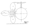
- the reverser will consist of three doors, one of which is approximately diametrically opposite the mast and the other two are located approximately symmetrically with respect to a horizontal plane passing through the axis of the engine.
- the doors are carried by four beams which can each form part of the wall of the cowling.
- the rear part of each door has, in plan, a concave configuration with, in the vicinity of the hinge pivots of the door, two lateral horns extending towards the rear and a narrowed middle part, the curvilinear rear edge of the door conforming to the shape of the central body of the motor when the door is in the inversion position.
- the front edge of the downstream mobile section will have a configuration corresponding to the configuration of the curvilinear rear edges of the doors, so that in the retracted door position, said rear edges of the doors fit into the front edge of the movable section, thus cooperating in the action of the jacks ensuring the maintenance of the doors in the closed position.
- the inverter structure described above can find an advantageous application in the case of motors in which a primary flow flow (hot) and a secondary flow flow (cold) are produced by to a front fan (or fan), these two flows being ejected through the single annular channel reserved between the central body and the cowling, the inverter of the invention in this case ensures practically the derivation of all the flows created by the engine and blower.
- the simplicity and the robustness of the inverter of the invention are particularly suitable for such a case because no fragile member (control jack or articulation pivot) is in contact with the bypass stream which is at a high temperature.
- the engine 3 is conventionally fixed to the fuselage 1 of the aircraft by a nacelle mast 2, the engine being surrounded by a tubular casing generally designated at 4.
- a front fan or blower 5 is associated with the reactor which in the example shown is of a particular type in which the rear forms a closed central body 3a, bulky and of great length in which the high pressure turbine, the chamber are housed combustion and all engine equipment.
- the hot primary flow is ejected by peripheral nozzles 3b opening in the annular channel CA reserved between the external wall of the engine 3 and the cowling 4 and which also serves for the flow of the secondary flow coming from the fan.
- the cowling 4 consists of three sections, namely a fixed upstream section 4a which surrounds the fan and the front of the motor, a downstream section 4b, or ferrule, which is movable in axial translation and an intermediate section 4c consisting of tilting doors forming the deflector mechanism.
- the two beams 7 are located on either side of the nacelle mast 2, while the two beams 6 are distributed opposite.
- each of the beams is housed a jack V, the free end of the rod 8 of which is articulated at 9 on the front structure 10 of the movable shell 4b, the movement of the cylinders ensuring the displacement of the shell along the longitudinal axis XX ' of the motor.
- said ferrule 4b has a substantially C section, its free edges being engaged in longitudinal slides (not shown) formed in the fixed structure of the nacelle mast and allowing the ferrule to be guided during its movement.
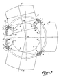
- Each door 11-12 and 13 is articulated by two lateral pivots 14 on two adjacent beams, the door 11 being articulated between the two beams 6 and the doors 12 and 13 respectively between a beam 7 and a beam 6 (see FIG. 3).
- the two pivots of each door are aligned on the same geometric axis and all the geometric axes of articulation of the doors are located in the same plane normal to the axis X-X "of the motor.
- pivots 14 are located at immediate vicinity of the rear end of the beams 67.
- Each door is also coupled to the movable ferrule 4b by a connecting rod 15 disposed in a radial plane of the motor and in the central region of the door.
- This connecting rod 15 is articulated at 16 in ears 23 secured to the external face of the door and at 17 on ears 35 provided on the front structure of the edge 10 before the ferrule.
- the articulation axis 16 of the connecting rod is located between the upstream edge of the door and the articulation pivots 14 of the door to the support beams.
- the rods 15 projecting outwards, it is possible, for aerodynamic reasons, to cover them with a fairing formed of shells 01, 02 and 03, the shell 01 being fixed on the door , the shell 03 on the connecting rod and the shell 02 on the ferrule 4b, The shells are free relative to each other to allow their relative displacement during the movement of the doors and the ferrule.
- the door has a curved outer wall 20 in the rear part of which are fixed folded sheet metal frames 22 and 24 in a U shape which provide rigidity at the rear edge of the door.
- a fitting 25 which, in the retracted door position (FIG. 4), is located under the articulation 17 of the connecting rod to the ferrule 4b and comes to crush a seal 36 fixed on the face front 10 of the ferrule, this seal 36 ensuring the sealing of the rear of the door.
- an internal wall 26 Inside the frames 22 and 24 is fixed an internal wall 26 whose rear end covers the fitting 25 to which it is fixed at 30.
- the internal wall 26 is fixed, at the front of the door, against the wall external 20 by means of a front frame 27 projecting towards the inside of the door and constituting a spoiler ensuring an additional deflection of the diverted flow when the door is open.
- the front of the door is sealed in the retracted position by means of a seal 28 fixed to the front of an internal wall PI secured to the fixed section 4a and extending it downstream, the seal 28 being crushed by the internal wall 26 of the door when the latter is retracted.
- the position of the seal 28 prevents any leakage of the flow towards the front of the doors when they are retracted.
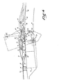
- the arrangement of the door is preferably such that in the retracted position, the plane of the pivots 14 of articulation of the doors to the beams is located between the axes 16 and 17 of articulation of the connecting rods at the door and the ferrule. Furthermore, the articulation point 16 of the connecting rod to the door is located at a distance from the downstream edge of the door such that, when the door is in the thrust reversal position shown in broken lines in FIG. 4, the articulation point 16 is located substantially at the same distance from the axis of the engine as the articulation point 17 of the connecting rod to the ferrule 4b.
- the trajectory of the axis 16 has been shown in T and it can be seen that this trajectory deviates very little from the generatrix of the cowling, which means that the connecting rods 15 will always be, during operation, in an almost horizontal position .
- each of the doors extends on either side of the articulation zone 14 to the beams.
- G more particularly the rear part of the doors which must ensure the obturation of the annular channel between engine and cowling during the thrust reversal.
- the rear part of the door has a substantially crescent shape with a curvilinear end edge 31 matching the shape of a fraction of the external wall of the motor.
- This rear part comprises, in the vicinity of the articulation pivots 14, two lateral horns 32 extending rearwards in the retracted door position, and a narrowed central part 32 '.
- the distance "1" measured between the lateral horns is less than the width L of the door, said horns being connected to the parallel lateral edges 34 of the door by parts 33 converging towards the axis of the door.
- the parts 33 of the adjacent doors come opposite one another under the beams 6 in order to achieve optimum sealing of the annular channel.
- the front edge of the wall 38 is cut to present a configuration corresponding to the configuration of the curved rear edges 31-32 of the doors.
- the edge of the wall 38 has a serrated shape 39 ⁇ 40 in which fits the rear of the door in the retracted door position shown in Figure 3. This interlocking of complementary shapes of the edges 31-32 and 39 ⁇ 40 cooperate in maintaining the doors in the closed position.
- the operation of the inverter is very simple.
- the actuating cylinders of the ferrule are retracted and the ferrule occupies the position in solid line in FIGS. 1 and 4.
- the three doors are folded down in the retracted position and the continuous internal wall of the cowling is constituted by an internal wall.
- PI extending the fixed section 4a beyond the junction plane between 4a and 4c, by the wall 26 of the doors and through the wall 38 of the shell.
- the ferrule cylinders are actuated which push it backwards.
- the connecting rods 15 then cause the doors to tilt and open, in the position indicated in broken lines, that is to say with an inclination "a" upstream relative to a vertical plane.
- Passages PA of substantially rectangular shape are then formed between the doors and the edge of the extension Pl, passages through which the primary and secondary flows are derived towards the outside and upstream.
- the three doors of the inverter burst the flow into three layers F i , F 2 and F 3 . Since a third of the flow is discharged through the door 11 laterally outwards, the size of the sheet F (deflected upwards in the vicinity of the directional structures D of the device located at the rear) as well as the size of the sheet F 2 (deflected towards the ground and capable of creating unfavorable interactions between the ground and the fuselage 1) is reduced accordingly, which significantly reduces the drawbacks linked to the arrangement of the sheets F, and F 2 .
Description
La présente invention concerne un inverseur de poussée pour moteur à réaction à capotage extérieur entourant une structure de moteur et délimitant avec celle-ci un canal annulaire pour l'écoulement d'un flux gazeux depuis une région amont vers une région aval, l'inversion de poussée étant produite par des portes susceptibles de basculer d'une position inactive à une position inclinée d'inversion de poussée dans laquelle elles s'étendent transversalement au canal annulaire qu'elles obturent, tout en libérant un passage dans le capotage, permettant au flux d'être dévié radialement vers l'extérieur du canal annulaire et vers l'amont, ces portes étant attelées par des bielles extérieures à une section aval de capotage qui est susceptible de se déplacer, sous l'action d'organes de commande, axialement par rapport à la structure du moteur.The present invention relates to a thrust reverser for a jet engine with an external cowling surrounding a motor structure and delimiting therewith an annular channel for the flow of a gas flow from an upstream region to a downstream region, the inversion thrust being produced by doors capable of tilting from an inactive position to an inclined position of reverse thrust in which they extend transversely to the annular channel which they close, while freeing a passage in the cowling, allowing the flow to be deflected radially outwards from the annular channel and upstream, these doors being coupled by external connecting rods to a downstream section of cowling which is capable of moving, under the action of control members, axially with respect to the structure of the engine.
Le brevet des Etats-Unis THEITS n° 3 280 562 décrit déjà un inverseur de poussée de ce type. Cependant, la structure d'inverseur décrite dans ce document est relativement compliquée, et son concept général entraîne la présence de certains défauts.US patent THEITS No. 3,280,562 already describes a thrust reverser of this type. However, the inverter structure described in this document is relatively complicated, and its general concept leads to the presence of certain faults.
Notamment, les portes constituent une structure qui se surajoute à celle du capotage extérieur du moteur; en position inactive, elles se situent à l'intérieur de ce capotage, d'où résulte une complication et une augmentation du poids.In particular, the doors constitute a structure which is added to that of the external cowling of the engine; in the inactive position, they are located inside this casing, which results in a complication and an increase in weight.
Chez THEITS, en outre, la cinématique de ces portes est compliquée. En effet, elles ne sont pas uniquement pivotantes, mais sont montées sur des poutres solidaires de la structure fixe par l'intermédiaire d'un système de galets qui leur impose non seulement de pivoter, mais également et préalablement de reculer lors de l'actionnement des vérins de manoeuvre commandant la position d'inversion de poussée.At THEITS, moreover, the kinematics of these doors is complicated. In fact, they are not only pivotable, but are mounted on beams integral with the fixed structure by means of a system of rollers which requires them not only to pivot, but also and beforehand to move back during actuation. operating cylinders controlling the thrust reversal position.
De plus, les organes de commande des portes, à savoir les vérins, n'agissent pas directement sur la section aval mobile du capotage; ils provoquent le recul de celle-ci seulement par l'intermédiaire des portes elles-mêmes et des bielles, ce qui soumet les bielles à des efforts de flexion; de ce fait, les portes elles-mêmes sont soumises aux efforts des vérins. En outre, on remarque que, chez THEITS, les vérins sont montés entre la structure fixe et une zone centrale des portes, ce qui contribue aussi à soumettre celles-ci à des efforts risquant de les déformer et place les vérins dans le flux chaud d'inversion de poussée, ce qui constitue un inconvénient majeur du système.In addition, the door control members, namely the jacks, do not act directly on the movable downstream section of the cowling; they cause the latter to retreat only by means of the doors themselves and the connecting rods, which subjects the connecting rods to bending forces; therefore, the doors themselves are subjected to the efforts of the cylinders. In addition, we note that, at THEITS, the cylinders are mounted between the fixed structure and a central zone of the doors, which also contributes to subjecting them to forces which risk deforming them and places the cylinders in the hot flow d 'reverse thrust, which is a major drawback of the system.
Le but de la présente invention est d'obtenir un inverseur de poussée du type général de celui mentionné au début, mais qui ne présente pas les inconvénients précités.The object of the present invention is to obtain a thrust reverser of the general type of that mentioned at the start, but which does not have the aforementioned drawbacks.
A cet effet, un inverseur de poussée du type en question sera, conformément à la présente invention, essentiellement caractérisé en ce que lesdites portes constituent des éléments d'une section intermédiaire du capotage située entre une section fixe amont et la section aval mobile de celui-ci, et, en position inactive, se trouvent dans l'alignement de ces sections amont et aval; en ce que ces portes sont montées pivotantes chacune sur un axe fixe solidaire de la section fixe amont; et en ce que lesdits organes de commande s'étendent directement entre ladite section fixe amont et la section mobile aval, latéralement par rapport auxdites portes, de sorte, d'une part que leur actionnement provoque un recul de ladite section mobile et, consécutivement, un basculement des portes en position d'inversion de poussée, seulement par l'intermédiaire d'une traction exercée par ladite section mobile sur lesdites bielles, et d'autre part qu'ils se trouvent en dehors du flux d'inversion de poussée.To this end, a thrust reverser of the type in question will, in accordance with the present invention, be essentially characterized in that said doors constitute elements of an intermediate section of the cowling situated between a fixed upstream section and the movable downstream section of that -ci, and, in the inactive position, are in the alignment of these upstream and downstream sections; in that these doors are pivotally mounted each on a fixed axis integral with the upstream fixed section; and in that said control members extend directly between said upstream fixed section and the downstream movable section, laterally with respect to said doors, so, on the one hand, that their actuation causes a retraction of said movable section and, consequently, a tilting of the doors in the thrust reversal position, only by means of a traction exerted by said movable section on said connecting rods, and on the other hand that they are located outside the thrust reversal flow.
Le fait que les portes constituent une partie du capotage permet l'obtention d'une simplification considérable et d'un allègement, puisqu'elles ont de la sorte un rôle qui est double. Le fait qu'elles soient montées sur des axes solidaires de la section fixe amont permet de simplifier aussi leur cinématique, puisque alors elles ne seront plus soumises qu'à des mouvements de pivotement.The fact that the doors constitute a part of the casing makes it possible to obtain considerable simplification and lightening, since they thus have a role which is twofold. The fact that they are mounted on axes integral with the upstream fixed section also makes it possible to simplify their kinematics, since then they will only be subjected to pivoting movements.
Enfin, et surtout, le fait que les organes de commande (les vérins) s'étendent directement entre la section fixe amont et la section mobile aval, latéralement par rapport aux portes, permet d'obtenir les deux importants résultats suivants: l'actionnement des vérins provoque un recul de la section mobile du capotage et consécutivement un basculement des portes en position d'inver- .sion de poussée seulement par l'intermédiaire d'une traction exercée par la section mobile sur les bielles, et, en outre, les vérins se trouvent en dehors du flux chaud d'inversion de poussée.Finally, and above all, the fact that the control members (the jacks) extend directly between the upstream fixed section and the downstream movable section, laterally with respect to the doors, makes it possible to obtain the following two important results: actuation cylinders causes a retraction of the movable section of the cowling and consequently a tilting of the doors in the thrust reversal position only by means of a traction exerted by the movable section on the connecting rods, and, moreover, the cylinders are outside the hot reverse thrust flow.
Selon une autre caractéristique importante de la présente invention, il peut également être prévu que chaque porte s'étend de part et d'autre de son articulation à des poutres solidaires de la section amont et recevant lesdits organes de commande.According to another important characteristic of the present invention, it can also be provided that each door extends on either side of its articulation to beams integral with the upstream section and receiving said control members.
De préférence, en outre, chaque bielle de porte est articulée d'une part au bord amont de la section mobile aval et d'autre part à la porte correspondante en une zone située entre le bord amont de la porte et la zone d'articulation de la porte aux poutres porteuses.Preferably, in addition, each door link is articulated on the one hand at the upstream edge of the downstream movable section and on the other hand at the corresponding door in a zone situated between the upstream edge of the door and the articulation zone from the door to the supporting beams.
Par ailleurs, chacune des portes est située entre deux poutres voisines et elle est articulée à chacune de ces portes par un pivot d'articulation latéral; en outre, chaque porte est équipée d'une seule bielle d'actionnement qui est placée entre les pivots d'articulation de la porte.Furthermore, each of the doors is located between two adjacent beams and it is articulated to each of these doors by a lateral articulation pivot; in addition, each door is equipped with a single actuating rod which is placed between the articulation pivots of the door.
La structure d'inverseur proposée ci-dessus peut notamment être adaptée au cas d'un moteur d'avion en configuration "nacelle latérale" dans laquelle le moteur est fixé par un mât à la structure porteuse.The inverter structure proposed above can in particular be adapted to the case of an aircraft engine in the "lateral nacelle" configuration in which the engine is fixed by a mast to the carrying structure.
Selon une forme de réalisation préférée de l'invention, dans un tel cas, l'inverseur sera constitué par trois portes dont l'une est à peu près diamétralement opposée au mât et les deux autres sont situées à peu près symétriquement par rapport à un plan horizontal passant par l'axe du moteur.According to a preferred embodiment of the invention, in such a case, the reverser will consist of three doors, one of which is approximately diametrically opposite the mast and the other two are located approximately symmetrically with respect to a horizontal plane passing through the axis of the engine.
Le jet inversé est, de ce fait, éclaté en trois nappes par l'intermédiaire des trois portes, cette solution présentant des avantages en ce qui concerne les interactions avec le sol et les organes de contrôle de l'avion. En effet, seulement un tiers du débit environ sera défléchi vers le sol, un tiers vers le haut, le tiers restant étant réfléchi vers l'extérieur, ce qui diminue d'autant les problèmes d'interaction du flux dévié avec le sol ou avec les organes de contrôle de l'avion.The reverse jet is therefore split in three tablecloths through the three doors, this solution having advantages with regard to interactions with the ground and the aircraft control bodies. Indeed, only about a third of the flow will be deflected towards the ground, a third upwards, the remaining third being reflected towards the outside, which reduces the problems of interaction of the deflected flow with the ground or with aircraft control bodies.
Les portes sont portées par quatre poutres qui peuvent former chacune une partie de la paroi du capotage.The doors are carried by four beams which can each form part of the wall of the cowling.
Afin de permettre l'obturation du canal annulaire en position d'inversion, la partie arrière de chaque porte présente, en plan, une configuration concave avec, au voisinage des pivots d'articulation de la porte, deux cornes latérales s'étendant vers l'arrière et une partie médiane rétrécie, l'arête arrière curviligne de la porte épousant la forme du corps central du moteur lorsque la porte est en position d'inversion. De préférence, l'arête avant de la section mobile aval présentera une configuration correspondant à la configuration des arêtes arrière curvilignes des portes, de telle sorte qu'en position de portes escamotées, lesdites arêtes arrière des portes s'emboîtent dans l'arête avant de la section mobile, en coopérant ainsi à l'action des vérins assurant le maintien des portes en position fermée.In order to allow the annular channel to be closed in the inversion position, the rear part of each door has, in plan, a concave configuration with, in the vicinity of the hinge pivots of the door, two lateral horns extending towards the rear and a narrowed middle part, the curvilinear rear edge of the door conforming to the shape of the central body of the motor when the door is in the inversion position. Preferably, the front edge of the downstream mobile section will have a configuration corresponding to the configuration of the curvilinear rear edges of the doors, so that in the retracted door position, said rear edges of the doors fit into the front edge of the movable section, thus cooperating in the action of the jacks ensuring the maintenance of the doors in the closed position.
Selon un aspect particulier de l'invention, la structure d'inverseur décrite ci-dessus peut trouver une application avantageuse dans le cas de moteurs dans lesquels sont produits un écoulement de flux primaire (chaud) et un écoulement de flux secondaire (froid) grâce à une soufflante (ou fan) frontal, ces deux flux étant éjectés par le canal annulaire unique réservé entre le corps central et le capotage, l'inverseur de l'invention assure dans ce cas pratiquement la dérivation de la totalité des écoulements créés par le moteur et la soufflante. La simplicité et la robustesse de l'inverseur de l'invention sont particulièrement adaptées à un tel cas car aucun organe fragile (vérin de commande ou pivot d'articulation) ne se trouve au contact du flux dérivé qui est à une température élevée.According to a particular aspect of the invention, the inverter structure described above can find an advantageous application in the case of motors in which a primary flow flow (hot) and a secondary flow flow (cold) are produced by to a front fan (or fan), these two flows being ejected through the single annular channel reserved between the central body and the cowling, the inverter of the invention in this case ensures practically the derivation of all the flows created by the engine and blower. The simplicity and the robustness of the inverter of the invention are particularly suitable for such a case because no fragile member (control jack or articulation pivot) is in contact with the bypass stream which is at a high temperature.
D'autres caractéristiques et avantages de la présente invention apparaîtront dans la description qui suit d'un exemple de réalisation de l'inverseur en référence aux dessins annexés dans lesquels:
- - la figure 1 est une vue en élavation schématique d'un moteur équipé d'un inverseur selon l'invention représenté en position escamotée;
- -.Ia figure 2 est une vue similaire à la figure 1 représentant l'inverseur en position déployée;
- - la figure 3 est une coupe transversale schématique selon la ligne III-III de la figure 2;
- - la figure 4 est un détail en coupe longitudinale d'une porte représentée en position escamotée en trait continu et en position déployée en traits interrompus; et
- - la figure 5 est un schéma d'un moteur à configuration "nacelle latérale" monté sur un fuselage d'avion et montrant la manière dont le flux est distribué en position d'inversion de poussée.
- - Figure 1 is a schematic sectional view of an engine equipped with an inverter according to the invention shown in the retracted position;
- FIG. 2 is a view similar to FIG. 1 showing the reverser in the deployed position;
- - Figure 3 is a schematic cross section along the line III-III of Figure 2;
- - Figure 4 is a detail in longitudinal section of a door shown in the retracted position in solid lines and in the deployed position in broken lines; and
- - Figure 5 is a diagram of an engine with "lateral nacelle" configuration mounted on an aircraft fuselage and showing the way in which the flow is distributed in the thrust reversal position.
Bien que l'invention puisse s'appliquer à différents types de moteur, dans sa description qui suit, on décrira à titre d'exemple non limitatif, un inverseur équipant un moteur d'avion à double flux en configuration "nacelle latérale".Although the invention can be applied to different types of engine, in its description which follows, a non-limiting example will be described, an inverter equipping an aircraft engine with double flow in "lateral nacelle" configuration.
Comme on le voit à la figure 5, le moteur 3 est fixé classiquement au fuselage 1 de l'avion par un mât nacelle 2, le moteur étant entouré par un capotage tubulaire désigné de façon générale en 4. Comme représenté à la figure 1, un fan ou soufflante 5 avant est associée au réacteur qui dans l'exemple représenté est d'un type particulier dans lequel l'arrière forme un corps central 3a fermé, volumineux et de grande longueur dans lequel sont logés la turbine haute pression, la chambre de combustion et l'ensemble des équipements du moteur. Le flux primaire chaud est éjecté par des tuyères périphériques 3b s'ouvrant dans le canal annulaire CA réservé entre la paroi externe du moteur 3 et le capotage 4 et qui sert également à l'écoulement du flux secondaire provenant du fan.As can be seen in FIG. 5, the
Selon l'invention, le capotage 4 est constitué de trois sections, à savoir une section fixe amont 4a qui entoure le fan et l'avant du moteur, une section aval 4b, ou virole, qui est mobile en translation axiale et une section intermédiaire 4c constituée de portes basculantes formant le mécanisme déflecteur.According to the invention, the cowling 4 consists of three sections, namely a fixed
Sur la paroi externe de la section fixe 4a sont prévues quatre poutres fixes 6 et 7 s'étendant parallèlement à l'axe du moteur et au-delà du plan P délimitant les sections 4a et 4c. Les deux poutres 7 (voir figure 3) sont situées de part et d'autre du mât nacelle 2, tandis que les deux poutres 6 sont distribuées à l'opposé.On the outer wall of the
Dans chacune des poutres est logé un vérin V dont l'extrémité libre de la tige 8 est articulée en 9 sur la structure frontale 10 de la virole mobile 4b, le mouvement des vérins assurant le déplacement de la virole selon l'axe longitudinal X-X' du moteur.In each of the beams is housed a jack V, the free end of the
En section transversale, ladite virole 4b a une section sensiblement en C, ses bords libres étant engagés dans des glissières longitudinales (non représentées) ménagées dans la structure fixe du mât nacelle et permettant le guidage de la virole lors de son déplacement.In cross section, said
Entre les quatre poutres 6-7 sont montées trois portes 11-12 et 13 qui, dans l'exemple représenté ont une forme générale en portion de tronc de cône. Chaque porte 11-12 et 13 est articulée par deux pivots latéraux 14 sur deux poutres voisines, la porte 11 étant articulée entre les deux poutres 6 et les portes 12 et 13 respectivement entre une poutre 7 et une poutre 6 (voir figure 3). Les deux pivots de chaque porte sont alignés sur un même axe géométrique et tous les axes géométriques d'articulation des portes sont situés dans un même plan normal à l'axe X-X" du moteur.Between the four beams 6-7 are mounted three doors 11-12 and 13 which, in the example shown have a general shape in portion of a truncated cone. Each door 11-12 and 13 is articulated by two
On notera, comme on le voit particulièrement à la figure 2, que les pivots 14 se trouvent au voisinage immédiat de l'extrémité arrière des poutres 67.It will be noted, as can be seen particularly in FIG. 2, that the
Chaque porte est attelée par ailleurs à la virole mobile 4b par une bielle 15 disposée dans un plan radial du moteur et dans la zone médiane de la porte. Cette bielle 15 est articulée en 16 dans des oreilles 23 solidaires de la face externe de la porte et en 17 sur des oreilles 35 prévues sur la structure frontale du bord 10 avant de la virole. L'axe d'articulation 16 de la bielle est situé entre le bord amont de la porte et les pivots d'articulation 14 de la porte aux poutres support. Dans l'exemple représenté, les bielles 15 étant en saillie vers l'extérieur, on peut prévoir, pour des raisons aérodynamiques, de les recouvrir d'un carénage formé de coquilles 01, 02 et 03, la coquille 01 étant fixée sur la porte, la coquille 03 sur la bielle et la coquille 02 sur la virole 4b, Les coquilles sont libres l'une par rapport à l'autre pour permettre leur déplacement relatif lors du mouvement des portes et de la virole.Each door is also coupled to the
La porte comporte une paroi extérieure 20 galbée dans la partie arrière de laquelle sont fixés des cadres transversaux en tôle pliée 22 et 24 en forme de U qui assurent la rigidité au niveau du bord arrière de porte.The door has a curved outer wall 20 in the rear part of which are fixed folded
Sur le cadre arrière 24 est fixée également une ferrure 25 qui, en position de porte escamotée (figure 4), se trouve sous l'articulation 17 de la bielle à la virole 4b et vient écraser un joint d'étanchéité 36 fixé sur la face frontale 10 de la virole, ce joint 36 assurant l'étanchéité de l'arrière de la porte.On the
A l'intérieur des cadres 22 et 24 est fixée une paroi interne 26 dont l'extrémité arrière couvre la ferrure 25 à laquelle elle est fixée en 30. La paroi interne 26 est fixée, à l'avant de la porte, contre la paroi externe 20 par l'intermédiaire d'un cadre avant 27 faisant saillie vers l'intérieur de la porte et constituant un becquet assurant une déflection supplémentaire du flux dévié lorsque la porte est ouverte. L'étanchéité de l'avant de la porte en position escamotée est réalisée grâce à un joint d'étanchéité 28 fixé à l'avant d'une paroi interne PI solidaire de la section fixe 4a et la prolongeant vers l'aval, le joint 28 étant écrasé par la paroi interne 26 de la porte lorsque celle-ci est escamotée. La position du joint 28 empêche toute fuite du flux vers l'avant des portes lorsqu'elles sont escamotées.Inside the
Comme on le voit sur la figure 4, l'agencement de la porte est de préférence tel qu'en position escamotée, le plan des pivots 14 d'articulation des portes aux poutres se trouve situé entre les axes 16 et 17 d'articulation des bielles à la porte et à la virole. Par ailleurs, le point d'articulation 16 de la bielle à la porte est situé à une distance du bord aval de la porte telle que, lorsque la porte est en position d'inversion de poussée représentée en trait interrompu à la figure 4, le point d'articulation 16 se trouve sensiblement à la meme distance de l'axe du moteur que le point d'articulation 17 de la bielle à la virole 4b. On a figuré en T la trajectoire de l'axe 16 et on constate que cette trajectoire s'écarte très peu de la génératrice du capotage, ce qui signifie que les bielles 15 se trouveront toujours, au cours du fonctionnement, dans une position presque horizontale.As seen in Figure 4, the arrangement of the door is preferably such that in the retracted position, the plane of the
Comme on l'a déjà indiqué, chacune des portes s'étend de part et d'autre de la zone d'articulation 14 aux poutres. On décrire G présent plus particulièrement la partie arrière des portes qui doit assurer l'obturation du canal annulaire entre moteur et capotage lors de l'inversion de poussée.As already indicated, each of the doors extends on either side of the
En vue en plan (voir figure 3), la partie arrière de la porte présente sensiblement une forme en croissant avec une arête d'extrémité 31 curviligne épousant la forme d'une fraction de la paroi externe du moteur.In plan view (see FIG. 3), the rear part of the door has a substantially crescent shape with a
Cette partie arrière comporte, au voisinage des pivots d'articulation 14, deux cornes latérales 32 s'étendant vers l'arrière en position de porte escamotée, et une partie médiane rétrécie 32'. La distance "1" mesurée entre les cornes latérales est inférieure à la largeur L de la porte, lesdites cornes étant reliées aux bords latéraux 34 parallèles de la porte par des parties 33 convergeant vers l'axe de la porte. Comme on le voit à la figure 3, en position de portes ouvertes, les parties 33 des portes adjacentes viennent en regard l'une de l'autre sous les poutres 6 afin de réaliser une obturation optimale du canal annulaire. Avec la forme décrite ci-dessus pour les portes 12 et 13, en position des portes ouvertes, des espaces non obturés Si et S2 demeurent de part et d'autre du mât de servitude moteur MS reliant le moteur 3 au mât 2. Dans certaines circonstances, il peut être nécessaire de conserver de tels espaces S, et S2 du canal CA non obturés. Toutefois, si l'obturation aussi complète que possible du canal était désirée, on pourrait, en variante, fixer à la corne 32 des portes 12 et 13 la plus voisine du mât MS, une palette de prolongement que l'on a schématisée en trait interrompu en 100, cette palette s'étendant jusqu'au voisinage immédiat du mât de servitude MS. On décrira également rapidement la structure de la virole 4b. Celle-ci comporte une paroi externe 37 et une paroi interne 39 liées l'une à l'autre à l'avant par une poutre frontale qui constitue le bord 10.This rear part comprises, in the vicinity of the articulation pivots 14, two
L'arête avant de la paroi 38 est découpée pour présenter une configuration correspondant à la configuration des arêtes arrière curvilignes 31-32 des portes. A cet égard, au niveau de chaque porte, l'arête de la paroi 38 présente une forme dentelée 39―40 dans laquelle vient s'emboîter l'arrière de la porte en position de porte escamotée représentée à la figure 3. Cet emboîtement des formes complémentaires des arêtes 31-32 et 39―40 coopère au maintien des portes en position fermée.The front edge of the wall 38 is cut to present a configuration corresponding to the configuration of the curved rear edges 31-32 of the doors. In this regard, at each door, the edge of the wall 38 has a
Le fonctionnement de l'inverseur est très simple. En vol normal, les vérins d'actionnement de la virole sont rentrés et la virole occupe la position en trait continu des figures 1 et 4. Les trois portes sont rabatues en position escamotée et la paroi interne continue du capotage est constituée par une paroi interne PI prolongeant la section fixe 4a au-delà du plan de jonction entre 4a et 4c, par la paroi 26 des portes et par la paroi 38 de la virole.The operation of the inverter is very simple. In normal flight, the actuating cylinders of the ferrule are retracted and the ferrule occupies the position in solid line in FIGS. 1 and 4. The three doors are folded down in the retracted position and the continuous internal wall of the cowling is constituted by an internal wall. PI extending the fixed
Pour déployer l'inverseur, on actionne les vérins de virole qui repoussent celle-ci vers l'arrière. Les bielles 15 provoquent alors le basculement des portes et leur ouverture, dans la position indiquée en trait interrompu, c'est-à-dire avec une inclinaison "a" vers l'amont par rapport à un plan vertical. Des passages PA de forme sensiblement rectangulaire (figure 2) sont alors ménagés entre les portes et le bord du prolongement Pl, passages par lesquels les flux primaire et secondaire sont dérivés vers l'extérieur et vers l'amont.To deploy the reverser, the ferrule cylinders are actuated which push it backwards. The connecting
Ainsi qu'on peut le voir particulièrement à la figure 5, les trois portes de l'inverseur font éclater le flux en trois nappes Fi, F2 et F3. Etant donné que le tiers du flux est rejeté par la porte 11 latéralement vers l'extérieur, l'importance de la nappe F, (déviée vers le haut au voisinage des structures directionnelles D de l'appareil situées à l'arrière) ainsi que l'importance de la nappe F2 (déviée vers le sol et susceptible de créer des interactions défavorables entre le sol et le fuselage 1) se trouvent réduites d'autant, ce qui diminue sensiblement les inconvénients liés à la disposition des nappes F, et F2.As can be seen particularly in FIG. 5, the three doors of the inverter burst the flow into three layers F i , F 2 and F 3 . Since a third of the flow is discharged through the
Claims (15)
Applications Claiming Priority (2)
| Application Number | Priority Date | Filing Date | Title |
|---|---|---|---|
| FR8014907 | 1980-07-04 | ||
| FR8014907A FR2486153B1 (en) | 1980-07-04 | 1980-07-04 | DRIVE INVERTER FOR A REACTION ENGINE, IN PARTICULAR FOR EQUIPPING AN AIRCRAFT |
Publications (2)
| Publication Number | Publication Date |
|---|---|
| EP0043764A1 EP0043764A1 (en) | 1982-01-13 |
| EP0043764B1 true EP0043764B1 (en) | 1985-05-02 |
Family
ID=9243853
Family Applications (1)
| Application Number | Title | Priority Date | Filing Date |
|---|---|---|---|
| EP81401059A Expired EP0043764B1 (en) | 1980-07-04 | 1981-07-01 | Thrust reverser for an aircraft jet engine |
Country Status (4)
| Country | Link |
|---|---|
| US (1) | US4410152A (en) |
| EP (1) | EP0043764B1 (en) |
| DE (1) | DE3170269D1 (en) |
| FR (1) | FR2486153B1 (en) |
Cited By (1)
| Publication number | Priority date | Publication date | Assignee | Title |
|---|---|---|---|---|
| EP4350140A1 (en) * | 2022-10-07 | 2024-04-10 | Rohr, Inc. | Thrust reverser system with angled door pivot axes |
Families Citing this family (47)
| Publication number | Priority date | Publication date | Assignee | Title |
|---|---|---|---|---|
| FR2506843B1 (en) * | 1981-05-29 | 1987-04-24 | Hurel Dubois Avions | PUSH-INVERSION DEVICE FOR AIRPLANE TURBOREACTOR |
| FR2611233B1 (en) * | 1987-02-19 | 1991-05-10 | Hurel Dubois Avions | FAN-TYPE AIRPLANE MOTOR-PROPELLER UNIT EQUIPPED WITH A PUSH-INVERTER WITH DOORS |
| FR2618852B1 (en) * | 1987-07-29 | 1989-11-10 | Hispano Suiza Sa | TURBOREACTOR DRIVE INVERTER PROVIDED WITH A FLOW RECTIFIER DEVICE |
| FR2618853B1 (en) * | 1987-07-29 | 1989-11-10 | Hispano Suiza Sa | TURBOREACTOR DRIVE INVERTER WITH MOBILE DOOR DEFLECTOR |
| FR2621082A1 (en) * | 1987-09-30 | 1989-03-31 | Hispano Suiza Sa | PUSH INVERTER OF TURBOJET WITH DOORS PROVIDED WITH A VEIN PROFILE PLATE |
| FR2627807B1 (en) * | 1988-02-25 | 1990-06-29 | Hispano Suiza Sa | DOUBLE-FLOW TURBOREACTOR DRIVE INVERTER HAVING DEVIATION EDGES WITH MOVABLE LIPS |
| FR2634251B1 (en) * | 1988-07-18 | 1993-08-13 | Hispano Suiza Sa | DOUBLE-FLOW TURBOREACTOR DRIVE INVERTER HAVING MOBILE DEVIATION EDGES |
| FR2638207B1 (en) * | 1988-10-20 | 1990-11-30 | Hispano Suiza Sa | TURBOJET DRIVE INVERTER WITH BALANCED PIVOTING DOORS |
| US5039171A (en) * | 1989-08-18 | 1991-08-13 | Societe Anonyme Dite Hispano-Suiza | Multi-panel thrust reverser door |
| FR2651278B1 (en) * | 1989-08-23 | 1994-05-06 | Hispano Suiza | INVERTER WITH GRIDS WITHOUT SLIDING COVER FOR TURBOREACTOR. |
| US5203164A (en) * | 1990-06-06 | 1993-04-20 | Paulson Allen E | Method and apparatus for quieting a turbojet engine |
| FR2669079B1 (en) * | 1990-11-14 | 1994-12-30 | Hurel Dubois Avions | IMPROVEMENT TO DOOR DRIVE INVERTERS FOR JET AIRCRAFT. |
| GB2252279A (en) * | 1991-02-01 | 1992-08-05 | Rolls Royce Plc | Thrust reverser |
| US5197693A (en) * | 1991-08-15 | 1993-03-30 | Rohr, Inc. | Aircraft turbine engine thrust reverser with sliding hinge actuator |
| FR2680547B1 (en) * | 1991-08-21 | 1993-10-15 | Hispano Suiza | TURBOREACTOR DRIVE INVERTER HAVING A DEVIATION EDGE WITH EVOLUTIVE CURVATURE. |
| FR2681101B1 (en) * | 1991-09-11 | 1993-11-26 | Hispano Suiza | PUSH INVERTER WITH IMPROVED PILOTAGE OF REVERSE FLOW PATCHES. |
| FR2730763B1 (en) * | 1995-02-21 | 1997-03-14 | Hispano Suiza Sa | DOWNSTREAM SHUTTER REVERSER FOR TURBOJET |
| FR2736682B1 (en) * | 1995-07-12 | 1997-08-14 | Hispano Suiza Sa | DOUBLE FLOW TURBOMACHINE DRIVE INVERTER WITH DISSYMMETRIC DOORS |
| US5730392A (en) * | 1995-09-22 | 1998-03-24 | Aeronautical Concept Of Exhaust, Ltd. | Adjustable fairing for thrust reversers |
| FR2742482B1 (en) * | 1995-12-19 | 1998-02-06 | Hurel Dubois Avions | ADJUSTABLE SECTION TUBE THRUST CHANGEOVER FOR JET ENGINE |
| DE69616739T2 (en) * | 1996-02-08 | 2002-09-05 | Hurel Dubois Avions | Sealing arrangement for swiveling thrust reverser flap |
| EP0852290A1 (en) | 1996-12-19 | 1998-07-08 | SOCIETE DE CONSTRUCTION DES AVIONS HUREL-DUBOIS (société anonyme) | Thrust reverser for high bypass fan engine |
| FR2768773B1 (en) * | 1997-09-25 | 1999-11-05 | Hispano Suiza Sa | INTERNAL SHELL TURBOREACTOR DRIVE INVERTER |
| US6311928B1 (en) * | 2000-01-05 | 2001-11-06 | Stage Iii Technologies, L.C. | Jet engine cascade thrust reverser for use with mixer/ejector noise suppressor |
| DE60021585D1 (en) * | 2000-12-18 | 2005-09-01 | Techspace Aero Sa | Test bench for thrust reverser |
| US6938408B2 (en) * | 2001-04-26 | 2005-09-06 | Propulsion Vectoring, L.P. | Thrust vectoring and variable exhaust area for jet engine nozzle |
| FR2962977B1 (en) * | 2010-07-20 | 2012-08-17 | Airbus Operations Sas | NACELLE FOR AIRCRAFT |
| US9611048B2 (en) | 2013-02-22 | 2017-04-04 | United Technologies Corporation | ATR axial V-groove |
| US9581108B2 (en) * | 2013-02-22 | 2017-02-28 | United Technologies Corporation | Pivot thrust reverser with multi-point actuation |
| US9435293B2 (en) | 2013-02-22 | 2016-09-06 | United Technologies Corporation | Full ring sliding nacelle with thrust reverser |
| US9447749B2 (en) * | 2013-04-02 | 2016-09-20 | Rohr, Inc. | Pivoting blocker door for thrust reverser |
| FR3016863B1 (en) * | 2014-01-29 | 2017-05-26 | Snecma | NACELLE FOR AIRCRAFT TURBO AIRCRAFT |
| US10344709B2 (en) * | 2015-09-10 | 2019-07-09 | Honeywell International Inc. | System and method for reducing idle thrust in a translating cowl thrust reverser |
| FR3057617B1 (en) * | 2016-10-17 | 2020-10-16 | Airbus | NACELLE OF A TURBOREACTOR CONTAINING A INVERTER FLAP |
| FR3060660B1 (en) * | 2016-12-20 | 2019-05-17 | Safran Nacelles | AIRCRAFT TURBO BURNER BOAT, PROPULSIVE AND AIRCRAFT ASSEMBLY COMPRISING SUCH A NACELLE |
| FR3062371B1 (en) | 2017-01-31 | 2019-03-29 | Airbus | NACELLE OF A TURBOJET ENGINE COMPRISING AN INVERTER SHUTTER |
| RU2663249C1 (en) | 2017-03-16 | 2018-08-03 | Акционерное общество "Объединенная двигателестроительная корпорация" (АО "ОДК") | Method for manufacturing sections of a thrust reverser bearing grid |
| FR3064686B1 (en) * | 2017-03-30 | 2019-04-19 | Airbus Operations | NACELLE OF A TURBOJET ENGINE COMPRISING AN INVERTER SHUTTER |
| FR3066232B1 (en) * | 2017-05-15 | 2019-05-03 | Airbus | NACELLE OF A TURBOJET ENGINE COMPRISING AN INVERTER SHUTTER |
| US10865737B2 (en) * | 2017-08-29 | 2020-12-15 | Honeywell International Inc. | Hidden linkage for a translating cowl thrust reverser |
| US10724474B2 (en) | 2018-05-01 | 2020-07-28 | Rohr, Inc. | Hybrid articulating/translating trailing edge reverser |
| US10830177B2 (en) | 2018-05-01 | 2020-11-10 | Rohr, Inc. | Articulating pivot point post-exit thrust reverser |
| US11053887B2 (en) | 2018-07-02 | 2021-07-06 | Rohr, Inc. | Thrust reverser with displaceable trailing edge body |
| US11187187B2 (en) | 2018-08-06 | 2021-11-30 | Rohr, Inc. | Thrust reverser |
| FR3099221B1 (en) * | 2019-07-22 | 2022-08-26 | Safran Nacelles | Aircraft seal |
| FR3111952B1 (en) * | 2020-06-25 | 2022-08-26 | Safran Nacelles | Three-door thrust reverser |
| FR3122219B1 (en) | 2021-04-21 | 2023-07-14 | Safran Nacelles | Thrust reverser including tilting doors and sliding aft shroud |
Family Cites Families (19)
| Publication number | Priority date | Publication date | Assignee | Title |
|---|---|---|---|---|
| GB812167A (en) * | 1956-04-17 | 1959-04-22 | Rolls Royce | Improvements in or relating to jet nozzles for jet-propulsion purposes |
| US3050937A (en) * | 1958-06-09 | 1962-08-28 | Boeing Co | Reversible thrust jet engines and controls therefor |
| US3036431A (en) * | 1959-09-08 | 1962-05-29 | Boeing Co | Thrust reverser for jet engines |
| US3097484A (en) * | 1960-06-13 | 1963-07-16 | Thrust reversers for jet engines | |
| GB1052963A (en) * | 1963-09-30 | |||
| US3279182A (en) * | 1965-06-07 | 1966-10-18 | Gen Electric | Thrust reverser |
| FR1482538A (en) * | 1965-06-07 | 1967-05-26 | Gen Electric | Thrust reverser |
| GB1130268A (en) * | 1967-07-01 | 1968-10-16 | Rolls Royce | Improvements in or relating to gas turbine by-pass engines |
| GB1177864A (en) * | 1968-04-09 | 1970-01-14 | Rolls Royce | Thrust Reverser or Spoiler |
| US3612401A (en) * | 1970-01-29 | 1971-10-12 | Rohr Corp | Thrust-reversing apparatus for turbofan jet engine |
| US3599874A (en) * | 1970-03-23 | 1971-08-17 | Rohr Corp | Thrust-reversing apparatus |
| US3665709A (en) * | 1970-06-04 | 1972-05-30 | Rohr Corp | Thrust reversing apparatus |
| US3601992A (en) * | 1970-06-10 | 1971-08-31 | Rohr Corp | Thrust reversing apparatus |
| US3605411A (en) * | 1970-07-01 | 1971-09-20 | Rohr Corp | Thrust reversing apparatus |
| US3684183A (en) * | 1970-09-16 | 1972-08-15 | Rohr Corp | Thrust controlling apparatus |
| US3699682A (en) * | 1971-01-04 | 1972-10-24 | Mc Donnell Douglas Corp | Turbofan engine thrust reverser |
| US3815357A (en) * | 1971-01-28 | 1974-06-11 | Rohr Industries Inc | Thrust reversing apparatus |
| US4073440A (en) * | 1976-04-29 | 1978-02-14 | The Boeing Company | Combination primary and fan air thrust reversal control systems for long duct fan jet engines |
| GB1534583A (en) * | 1976-06-08 | 1978-12-06 | Short Bros Ltd | Reversal of thrust in gas turbine engines |
-
1980
- 1980-07-04 FR FR8014907A patent/FR2486153B1/en not_active Expired
-
1981
- 1981-07-01 DE DE8181401059T patent/DE3170269D1/en not_active Expired
- 1981-07-01 EP EP81401059A patent/EP0043764B1/en not_active Expired
- 1981-07-01 US US06/279,238 patent/US4410152A/en not_active Expired - Lifetime
Cited By (1)
| Publication number | Priority date | Publication date | Assignee | Title |
|---|---|---|---|---|
| EP4350140A1 (en) * | 2022-10-07 | 2024-04-10 | Rohr, Inc. | Thrust reverser system with angled door pivot axes |
Also Published As
| Publication number | Publication date |
|---|---|
| DE3170269D1 (en) | 1985-06-05 |
| US4410152A (en) | 1983-10-18 |
| FR2486153B1 (en) | 1985-10-04 |
| FR2486153A1 (en) | 1982-01-08 |
| EP0043764A1 (en) | 1982-01-13 |
Similar Documents
| Publication | Publication Date | Title |
|---|---|---|
| EP0043764B1 (en) | Thrust reverser for an aircraft jet engine | |
| CA1329487C (en) | Turbojet thrust reverser with balanced pivoting doors | |
| EP0067747B1 (en) | Thrust reverser for a jet engine | |
| EP0281455B1 (en) | Fan jet engine with a thrust reverser | |
| EP0757170B1 (en) | Jet engine thrust reverser with a single door | |
| WO2009136096A2 (en) | Bypass turbojet engine nacelle | |
| FR2711733A1 (en) | Thrust reverser with jet engine doors equipped with an auxiliary flap. | |
| WO2010061107A1 (en) | Thrust reverser for a turbofan engine nacelle | |
| EP2509870B1 (en) | Engine nacelle aft door assembly | |
| CA2243099C (en) | Turbofan thrust reverser with axially guided blockers attached to the primary cowling | |
| WO1996038661A1 (en) | Double door thrust reverser assembly | |
| WO1999051870A1 (en) | Turbojet thrust reverser with doors forming scoops associated to an articulated external cowling | |
| EP0692619B1 (en) | Double flux turbine thrust reverser with external blocker flaps | |
| WO1998055755A1 (en) | Turbojet thrust reverser with doors forming scoops associated with a mobile deflector | |
| WO2008139048A2 (en) | Nacelle for turbojet jet fitted with a single door thrust reverser system | |
| FR2966882A1 (en) | THRUST INVERTER FOR AIRCRAFT TURBOJET ENGINE WITH REDUCED ACTUATOR NUMBERS | |
| FR2764340A1 (en) | DRIVE INVERTER OF TURBOJET WITH DOORS PROVIDED WITH A MOBILE SPOILER WITH OPTIMIZED DRIVE | |
| EP0764779A1 (en) | Thrust reverser with doors linked to a primary panel | |
| FR2602274A1 (en) | Adjustable cross-section, convergent/divergent jet nozzle | |
| EP0859142B1 (en) | Thrust reverser for high by-pass ratio turbofan | |
| EP0362051B1 (en) | Bidimensional ejection nozzle for a turbine and its control system | |
| FR2927956A1 (en) | THRUST INVERTER FOR DOUBLE FLOW TURBOREACTOR NACELLE | |
| FR2724977A1 (en) | Variable convergent-divergent nozzle for gas turbine engine jet pipe | |
| FR2625261A1 (en) | Turbojet thrust reverser with obstacles connected to the primary hood | |
| EP0131079A1 (en) | Thrust reverser with a deflector door, especially for an aircraft jet engine |
Legal Events
| Date | Code | Title | Description |
|---|---|---|---|
| PUAI | Public reference made under article 153(3) epc to a published international application that has entered the european phase |
Free format text: ORIGINAL CODE: 0009012 |
|
| AK | Designated contracting states |
Designated state(s): DE GB NL |
|
| 17P | Request for examination filed |
Effective date: 19811205 |
|
| GRAA | (expected) grant |
Free format text: ORIGINAL CODE: 0009210 |
|
| AK | Designated contracting states |
Designated state(s): DE GB NL |
|
| REF | Corresponds to: |
Ref document number: 3170269 Country of ref document: DE Date of ref document: 19850605 |
|
| PLBE | No opposition filed within time limit |
Free format text: ORIGINAL CODE: 0009261 |
|
| STAA | Information on the status of an ep patent application or granted ep patent |
Free format text: STATUS: NO OPPOSITION FILED WITHIN TIME LIMIT |
|
| 26N | No opposition filed | ||
| PGFP | Annual fee paid to national office [announced via postgrant information from national office to epo] |
Ref country code: GB Payment date: 19990720 Year of fee payment: 19 |
|
| PGFP | Annual fee paid to national office [announced via postgrant information from national office to epo] |
Ref country code: NL Payment date: 19990730 Year of fee payment: 19 Ref country code: DE Payment date: 19990730 Year of fee payment: 19 |
|
| PG25 | Lapsed in a contracting state [announced via postgrant information from national office to epo] |
Ref country code: GB Free format text: LAPSE BECAUSE OF NON-PAYMENT OF DUE FEES Effective date: 20000701 |
|
| PG25 | Lapsed in a contracting state [announced via postgrant information from national office to epo] |
Ref country code: NL Free format text: LAPSE BECAUSE OF NON-PAYMENT OF DUE FEES Effective date: 20010201 |
|
| GBPC | Gb: european patent ceased through non-payment of renewal fee |
Effective date: 20000701 |
|
| NLV4 | Nl: lapsed or anulled due to non-payment of the annual fee |
Effective date: 20010201 |
|
| PG25 | Lapsed in a contracting state [announced via postgrant information from national office to epo] |
Ref country code: DE Free format text: LAPSE BECAUSE OF NON-PAYMENT OF DUE FEES Effective date: 20010501 |