EP0043724B2 - Kontrollmarke für Kunststoffbahnen oder -bogen mit Umsetzung der elektromagnetischen Wellenlänge - Google Patents
Kontrollmarke für Kunststoffbahnen oder -bogen mit Umsetzung der elektromagnetischen Wellenlänge Download PDFInfo
- Publication number
- EP0043724B2 EP0043724B2 EP81303070A EP81303070A EP0043724B2 EP 0043724 B2 EP0043724 B2 EP 0043724B2 EP 81303070 A EP81303070 A EP 81303070A EP 81303070 A EP81303070 A EP 81303070A EP 0043724 B2 EP0043724 B2 EP 0043724B2
- Authority
- EP
- European Patent Office
- Prior art keywords
- web
- mark
- radiation
- wavelength
- electromagnetic radiation
- Prior art date
- Legal status (The legal status is an assumption and is not a legal conclusion. Google has not performed a legal analysis and makes no representation as to the accuracy of the status listed.)
- Expired - Lifetime
Links
- 239000004033 plastic Substances 0.000 title abstract description 31
- 229920003023 plastic Polymers 0.000 title abstract description 31
- 230000005855 radiation Effects 0.000 claims abstract description 36
- 230000005670 electromagnetic radiation Effects 0.000 claims abstract description 30
- 238000004519 manufacturing process Methods 0.000 claims abstract description 19
- 230000004044 response Effects 0.000 claims abstract description 10
- 238000004806 packaging method and process Methods 0.000 claims abstract description 6
- 239000011368 organic material Substances 0.000 claims abstract 6
- 239000000463 material Substances 0.000 claims description 30
- 150000001875 compounds Chemical class 0.000 claims description 12
- 238000001514 detection method Methods 0.000 claims description 7
- 238000000034 method Methods 0.000 claims description 6
- PJANXHGTPQOBST-UHFFFAOYSA-N stilbene Chemical compound C=1C=CC=CC=1C=CC1=CC=CC=C1 PJANXHGTPQOBST-UHFFFAOYSA-N 0.000 claims description 6
- 235000021286 stilbenes Nutrition 0.000 claims description 6
- 239000012815 thermoplastic material Substances 0.000 claims description 6
- PJANXHGTPQOBST-VAWYXSNFSA-N Stilbene Natural products C=1C=CC=CC=1/C=C/C1=CC=CC=C1 PJANXHGTPQOBST-VAWYXSNFSA-N 0.000 claims description 5
- 150000008040 ionic compounds Chemical class 0.000 claims description 4
- -1 polyethylene Polymers 0.000 claims description 4
- ZYGHJZDHTFUPRJ-UHFFFAOYSA-N coumarin Chemical compound C1=CC=C2OC(=O)C=CC2=C1 ZYGHJZDHTFUPRJ-UHFFFAOYSA-N 0.000 claims description 3
- 235000001671 coumarin Nutrition 0.000 claims description 3
- 230000003252 repetitive effect Effects 0.000 claims description 3
- KBVBZJLGCBJUSU-UHFFFAOYSA-N stilbene;triazine Chemical class C1=CN=NN=C1.C=1C=CC=CC=1C=CC1=CC=CC=C1 KBVBZJLGCBJUSU-UHFFFAOYSA-N 0.000 claims description 3
- 238000001228 spectrum Methods 0.000 claims description 2
- 239000004698 Polyethylene Substances 0.000 claims 1
- 230000001276 controlling effect Effects 0.000 claims 1
- 230000002596 correlated effect Effects 0.000 claims 1
- 229960000956 coumarin Drugs 0.000 claims 1
- 238000007689 inspection Methods 0.000 claims 1
- 229920000573 polyethylene Polymers 0.000 claims 1
- 238000000926 separation method Methods 0.000 claims 1
- 238000001429 visible spectrum Methods 0.000 claims 1
- 239000002966 varnish Substances 0.000 description 10
- 239000000975 dye Substances 0.000 description 8
- 239000011888 foil Substances 0.000 description 7
- 150000002894 organic compounds Chemical class 0.000 description 6
- 239000000126 substance Substances 0.000 description 6
- 239000003990 capacitor Substances 0.000 description 4
- 230000008859 change Effects 0.000 description 4
- 239000000990 laser dye Substances 0.000 description 4
- LFQSCWFLJHTTHZ-UHFFFAOYSA-N Ethanol Chemical compound CCO LFQSCWFLJHTTHZ-UHFFFAOYSA-N 0.000 description 3
- 239000007788 liquid Substances 0.000 description 3
- 239000000049 pigment Substances 0.000 description 3
- CFNMUZCFSDMZPQ-GHXNOFRVSA-N 7-[(z)-3-methyl-4-(4-methyl-5-oxo-2h-furan-2-yl)but-2-enoxy]chromen-2-one Chemical compound C=1C=C2C=CC(=O)OC2=CC=1OC/C=C(/C)CC1OC(=O)C(C)=C1 CFNMUZCFSDMZPQ-GHXNOFRVSA-N 0.000 description 2
- 125000004432 carbon atom Chemical group C* 0.000 description 2
- 239000003086 colorant Substances 0.000 description 2
- 230000007423 decrease Effects 0.000 description 2
- 229910052751 metal Inorganic materials 0.000 description 2
- 239000002184 metal Substances 0.000 description 2
- 230000005012 migration Effects 0.000 description 2
- 238000013508 migration Methods 0.000 description 2
- 239000000203 mixture Substances 0.000 description 2
- 230000008569 process Effects 0.000 description 2
- 239000011347 resin Substances 0.000 description 2
- 229920005989 resin Polymers 0.000 description 2
- 150000001629 stilbenes Chemical class 0.000 description 2
- XLYOFNOQVPJJNP-UHFFFAOYSA-N water Substances O XLYOFNOQVPJJNP-UHFFFAOYSA-N 0.000 description 2
- 150000000183 1,3-benzoxazoles Chemical class 0.000 description 1
- SIKJAQJRHWYJAI-UHFFFAOYSA-O 1H-indol-1-ium Chemical compound C1=CC=C2[NH2+]C=CC2=C1 SIKJAQJRHWYJAI-UHFFFAOYSA-O 0.000 description 1
- ZTGKHKPZSMMHNM-UHFFFAOYSA-N 3-(2-phenylethenyl)benzene-1,2-disulfonic acid Chemical class OS(=O)(=O)C1=CC=CC(C=CC=2C=CC=CC=2)=C1S(O)(=O)=O ZTGKHKPZSMMHNM-UHFFFAOYSA-N 0.000 description 1
- VTRBOZNMGVDGHY-UHFFFAOYSA-N 6-(4-methylanilino)naphthalene-2-sulfonic acid Chemical compound C1=CC(C)=CC=C1NC1=CC=C(C=C(C=C2)S(O)(=O)=O)C2=C1 VTRBOZNMGVDGHY-UHFFFAOYSA-N 0.000 description 1
- OKTJSMMVPCPJKN-UHFFFAOYSA-N Carbon Chemical compound [C] OKTJSMMVPCPJKN-UHFFFAOYSA-N 0.000 description 1
- 239000004677 Nylon Substances 0.000 description 1
- 230000004075 alteration Effects 0.000 description 1
- 230000005540 biological transmission Effects 0.000 description 1
- 229910052799 carbon Inorganic materials 0.000 description 1
- 239000013522 chelant Substances 0.000 description 1
- CPCIOUMUZMHAAR-UHFFFAOYSA-N chromen-2-one;sodium Chemical compound [Na].C1=CC=C2OC(=O)C=CC2=C1 CPCIOUMUZMHAAR-UHFFFAOYSA-N 0.000 description 1
- 238000010276 construction Methods 0.000 description 1
- 150000004775 coumarins Chemical class 0.000 description 1
- 125000000332 coumarinyl group Chemical group O1C(=O)C(=CC2=CC=CC=C12)* 0.000 description 1
- 230000008021 deposition Effects 0.000 description 1
- NJDNXYGOVLYJHP-UHFFFAOYSA-L disodium;2-(3-oxido-6-oxoxanthen-9-yl)benzoate Chemical compound [Na+].[Na+].[O-]C(=O)C1=CC=CC=C1C1=C2C=CC(=O)C=C2OC2=CC([O-])=CC=C21 NJDNXYGOVLYJHP-UHFFFAOYSA-L 0.000 description 1
- 238000001914 filtration Methods 0.000 description 1
- 230000001678 irradiating effect Effects 0.000 description 1
- 230000001788 irregular Effects 0.000 description 1
- MOUPNEIJQCETIW-UHFFFAOYSA-N lead chromate Chemical compound [Pb+2].[O-][Cr]([O-])(=O)=O MOUPNEIJQCETIW-UHFFFAOYSA-N 0.000 description 1
- 229920001684 low density polyethylene Polymers 0.000 description 1
- 239000004702 low-density polyethylene Substances 0.000 description 1
- 159000000003 magnesium salts Chemical class 0.000 description 1
- 238000012986 modification Methods 0.000 description 1
- 230000004048 modification Effects 0.000 description 1
- 229920001778 nylon Polymers 0.000 description 1
- 239000002985 plastic film Substances 0.000 description 1
- XAEFZNCEHLXOMS-UHFFFAOYSA-M potassium benzoate Chemical compound [K+].[O-]C(=O)C1=CC=CC=C1 XAEFZNCEHLXOMS-UHFFFAOYSA-M 0.000 description 1
- IZHYRVRPSNAXGV-UHFFFAOYSA-M potassium;naphthalene-1-sulfonate Chemical compound [K+].C1=CC=C2C(S(=O)(=O)[O-])=CC=CC2=C1 IZHYRVRPSNAXGV-UHFFFAOYSA-M 0.000 description 1
- KXXXUIKPSVVSAW-UHFFFAOYSA-K pyranine Chemical group [Na+].[Na+].[Na+].C1=C2C(O)=CC(S([O-])(=O)=O)=C(C=C3)C2=C2C3=C(S([O-])(=O)=O)C=C(S([O-])(=O)=O)C2=C1 KXXXUIKPSVVSAW-UHFFFAOYSA-K 0.000 description 1
- 150000003839 salts Chemical class 0.000 description 1
- 238000007789 sealing Methods 0.000 description 1
- 239000004065 semiconductor Substances 0.000 description 1
- 230000035945 sensitivity Effects 0.000 description 1
- 239000012780 transparent material Substances 0.000 description 1
Images
Classifications
-
- B—PERFORMING OPERATIONS; TRANSPORTING
- B65—CONVEYING; PACKING; STORING; HANDLING THIN OR FILAMENTARY MATERIAL
- B65H—HANDLING THIN OR FILAMENTARY MATERIAL, e.g. SHEETS, WEBS, CABLES
- B65H23/00—Registering, tensioning, smoothing or guiding webs
- B65H23/04—Registering, tensioning, smoothing or guiding webs longitudinally
- B65H23/046—Sensing longitudinal register of web
Definitions
- This invention relates to a web or sheet article wherein the article is encoded with information that controls operations performed on or with the article.
- wavelength shifting materials are suitable for practice of the above invention.
- visible light detectors in conjunction with control marks which absorb ultraviolet light and emit visible light on articles otherthan webs.
- one proposal was to place a visible light emitting mark on a tube which, when detected by a visible light detector, was used to assist in rotational registration of the tube for sealing.
- the material that was used however, emits visible light only in the presence of high energy ultraviolet light with a wavelength of about 2540 angstroms. Such high energy radiation can be damaging to the eye and therefore not suitable for use as a mark unless safety precautions are taken.
- control circuitry is to accurately determine a mark's position on a moving web, it is imperative that the material comprising the mark not bleed or migrate through the web surface so as to enlarge the mark. Migration may also cause a mark to flow through one layer of plastic web to another producing a mark where none was intended.
- US-A-2,888,570 describes a moving opaque strip which may be made of metal, plastic or nylon, or it may comprise a woven belt.
- the strip is provided with luminescent strips or areas formed by deposition on the surface of the strip or belt of a dye or pigment such as chrome yellow covered by a layer of transparent material containing an inorganic fluorescent pigment placed upon the dye or pigment.
- FR-A-1,569,118 discloses marking of articles such as documents with metal chelate compounds.
- GB-A-1,468,013 discloses marking of webs with patterns detected by photocells.
- thermoplastic material as claimed in claim 1 and a method for controlling operations in the manufacture of a packaging article as claimed in claim 9.
- the presence of marks can be detected by irradiating the web with non-harmful electromagnetic radiation.
- the marks respond by emitting wavelength-shifted electromagnetic radiation which can be detected by a detector.
- Circuitry coupled to the detector provides signals which then initiate web control operations.
- a preferred mark includes an organic compound which emits wavelength-shifted radiation when exposed to incident electromagnetic radiation that is not harmful to the eye.
- the structure of the carbon atoms in the organic compound allows less energetic radiation to initiate re-radiation of a detectable nature. It is believed that this phenomena is due to the high energy of bound electrons shared between two or more carbon atoms. The high energy carbon electrons are excited into a high energy state by less energetic electromagnetic radiation.
- the organic compound is ionic or polar. This characteristic allows the compound to bond to either the plastic web or with a separate carrier substance which in turn bonds to the web.
- One class of organic compounds which emits wave-shifted electromagnetic radiation and does not migrate in plastic is ionic or polar stilbenes or derivatives of stilbenes. Compounds in this class have proven to be economical, emit detectable wavelength-shifted electromagnetic radiation in response to non-harmful incident electromagnetic radiation, and are soluble in a varnish which adheres to plastic.
- a preferred material is sold by Sandoz Colors and Chemicals Corporation under the tradename TH-40 and comprises a disulfonated diamino stilbene-triazine in liquid form.
- the preferred mark includes a disulfonated stilbene.
- Electromagnetic wavelength-shifting materials such as TH-40, laser dyes, and biological dyes have all been used with success.
- the wavelength-shifting compound is added to a non-migrating varnish which comprises an alcohol, resin mixture.
- a non-migrating varnish which comprises an alcohol, resin mixture.
- the compound To be compatible with the varnish the compound must be soluble in it. Ionic compounds are typically water soluble or hydrophilic and therefore also soluble in the varnish.
- Marks which include such compounds may be either transparent or camouflaged in use by a suitable background. If the marks are transparent they may be used on plastic webs which are either clear or colored. If the marks are visible they can be affixed on a background which conceals their presence from view.
- one object of the present invention is to utilize control marks with a plastic web which do not migrate when affixed to the web. Another object is the provision of a control mark which is readily detectable when exposed to incident non-harmful electromagnetic radiation.
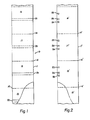
- a plastic heat sealable article of manufacture 10 comprising a double ply web 11 is illustrated.
- Each ply is segmented along its length by a series of laterally extending perforations 14 to form a series of packaging articles in the form of sleeve segments 16-19.
- Each sleeve segment is heat sealed along its edges and when disconnected from the web can be used as a label which slips over a bottle or other object.
- the segments 16-19 illustrated in Figure 1 are clear plastic with no printing or design yet added.
- a transparent colorless marking 20 shown in phantom in Figure 1.
- the marking 20 When exposed to incident electromagnetic radiation of an appropriate wavelength the marking 20 emits a wavelength-shifted electromagnetic output to allow detection of the presence of the mark. in the preferred embodiments the mark is invisible under daylight and emits wavelength-shifted radiation in response to non-harmful incident electromagnetic radiation.
- the repetitive markings 20 are used both in fabricating the series of sleeves from a web and in use of the web of fabricated sleeves at locations removed from the fabricating location. During the fabricating process, for example, the markings 20 are used to coordinate application of the perforations 14 as the web moves past a cutting station. Once the double ply web has been perforated it is typically stored on rolls for transportation to a separate facility where the segmented sleeves are applied to bottles or other cylindrical containers. During such a label application process the markings 20 can be used to initiate and control the application of the segmented sleeves to the bottles.
- Figure 2 comprises a double ply web 11' segmented by perforations 14' into a series of connected sleeves but wherein the marks do not extend across the width of the web and where more than one mark is applied to each segmented sleeve.
- the web construction shown in Figure 2 has three distinct marks 22, 24, 26 applied to each sleeve segment.
- the embodiment shown in Figure 2 comprises a clear plastic web and the markings are again transparent but emit wave-shifted electromagnetic radiation under incident low energy electromagnetic radiation of a non-harmful wavelength.
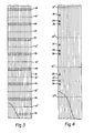
- the printed webs may include any marking scheme.
- the Figure 3 web 12 includes a laterally extending line or mark 30 across the width of the web and the web 12' shown in Figure 4 includes a series of three discrete marks 32, 34, 36 along the edge of an uppermost web ply. The markings have been lined to indicate they are red and thus are camouflaged by the red webs.
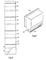
- FIG. 5 shows a web structure 13 comprising a series of connected plastic bags separated by heat seals 37.
- Each bag includes a single ply perforation 38 which forms an opening to the bag.
- Extending across one ply of each bag is also a transparent wave shifting marking 20' similar to the marking 20 shown in Figure 1, which allows detection of the presence of that marking as the web moves past an appropriate detector.
- a series of bags may include areas of printing, in which case the markings may be colored and camouflaged.
- markings 20' might therefore be used to control application of a series of perforations through the seals 37 to allow the bags to be separated.
- the markings might also be affixed to a foil in a non-consistent or non- repetitive pattern so as to allow random operations to be performed to the foil.
- the preferred marking material for plastic webs made from low density polyethylene or other heat sealable materials is an ink comprising 93% varnish, 4% Sandoz TH-40 and 3% wax.
- the Sandoz TH-40 is the wavelength-shifting material and includes a disulfonated diamino stilbene-triazine in liquid form. It is commercially available from Sandoz Colors and Chemical Corporation.
- the wax is available from the Inmont Company under the designation 72 F9105.
- the varnish is a resin, alcohol mixture which in the preferred embodiment is 40% versamid 712 and 60% alcohol.
- the line markings 20, 30 and 20' illustrated in Figures 1,3, and 5 are affixed using a 100 line analox printing roller. Ink comprising these materials is colorless, transparent, non-migrating in plastic and emits wavelength-shifted electromagnetic radiation under incident radiation of about 3660 angstroms to produce radiation of about 4500 angstroms.
- a second stilbene compound sold under the tradename Phorite CL by the Verona Dyestuff division of the Mobay Chemical Corporation has provided acceptable emission when it comprises 3% of the ink.
- the Phorite CL is a stilbene disulfonic acid derivative in liquid form.
- a third stilbene marketed by the Mobay Chemical Corporation, which is suitable as a mark, is sold under the name Phorite BA.
- IR-125 is a dark red organic and ionic compound that is soluble in the varnish and that emits invisible radiation of about 9400 angstroms when irradiated with radiation having a wavelength of about 7950 angstroms.
- this material is an anhydro-1, 1 dimethyl-2(7-(1,1-dimethyl-3-(4-sulfobutyl)-2-(lH)-benz(e) indolinylidene)-1,3,5-hep- tatrienyI)3-(4-sulfobutyl)-1 H-benz(e)indolium with a molecular formula C 43 H 47 N 2 NaO 6 S 2 .
- a second example of a non-migrating ionic laser dye is 8-hydroxy-1, 3, 6 pyrenetrisulfonic acid trisodium salt which is also available from the Eastman Kodak Company. This material is of a blue color which is soluble in the varnish and emits electromagnetic radiation of a wave shifted nature.
- ionic biological dyes have also been found to be suitable as marking materials. These dyes are water soluble organic dyes which do not migrate in the plastic when used with the preferred varnish. Three examples of these biological dyes are soluble fluorescein, which is a disosium salt sold by the Aldrich Chemical Company; 8-anilino-1-napthalene sulfonic acid magnesium salt; and 6-(p-toluidino-Z naphthalene sulfonic acid potassium salt. The latter two are commercially available under the names 1-8 ANS magnesium salt and 2,6-TNS potassium salt respectively.
- Non-ionic organic wavelength-shifting compounds can be modified slightly to make them ionic and therefore non-migrating.
- Coumarines for example, normally migrate in plastic.
- An example of a non-migrating coumarin derivative is 4-methyl-7(sulfo methyl amino) coumarin sodium salt. When dissolved in the varnish described this material is clear and emits at 4750 angstroms under incident radiation of 3660 angstroms.
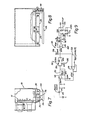
- a preferred detector unit 40 for detecting the presence of markings along a web is shown in Figure 6.
- This unit is mounted in proximity to a moving web by a detector mounting plate 42. The web is caused to move beneath the detector by an appropriate drive (not shown).
- a web guide 44 is positioned beneath the detector 40 and is attached to it by a suitable support 46. This guide 44 allows the web to pass beneath the detector at a distance close enough to allow the detector to sense the presence of the marking on the web.
- Control circuitry 110 mounted inside the unit 40 (see Figure 7) generates signals which control fabrication or manufacturing processes to be performed to the moving web.
- the detector unit Mounted inside the detector unit are two sources 50, 52 of incident electromagnetic radiation. Positioned between these sources is a detector 54 which senses the presence of markings on the web as the web passes over the web guide 44. In operation, the sources 50, 52 direct electromagnetic radiation of about 3660 angstroms to the web directly beneath the detector 54. When the incident radiation strikes a mark it causes a wavelength-shifted output to be emitted from that mark.
- a filter 56 for filtering out electromagnetic radiation of wavelengths other than the wavelengths emitted by the marking.
- the filter enhances sensitivity by preventing radiation reflected from the web from reaching the detector. More specifically the filter sufficiently blocks transmission of reflected mark-stimulating radiation so that such reflections will not cause false signals when marks are not present. Reflection of electromagnetic radiation that is ambient to the machine is not a problem because its intensity, in any location occupied by humans, is not high enough to cause reflections which will cause the detector to emit false signals. Mark detection is enhanced by constructing the web guide support 46 to be adjustable to allow the distance between the web and the detector 54 to be optimized.
- Exemplary circuitry 110 for generating control voltages in response to the presence of the web markings is shown mounted inside the detector unit 40 on a printed circuit board 111. That circuitry 110 is electrically connected to a photo diode 113 in the detector 54. Three amplifiers 112, 114, 116 and a timer 118 respond to changes in photo diode resistance with changes in electromagnetic radiation intensity from the marking to generate a control output 120.
- the anode of that diode 113 is connected to a 12 volt source and the cathode coupled to a 1 megohm resistor. As the resistance decreases the current through the 1 megohm resistor increases causing a larger voltage to appear at a non-inverting (+) input to the first amplifier 112.
- This amplifier 112 is an operational amplifier and one suitable such amplifier is an LM324 op amp.
- An output 121 from the first operational amplifier 112 is coupled to a second operational amplifier 114 and further coupled to the inverting input of the first op amp 112 through a feedback network 122.
- the second operational amplifier 114 responds to the output 121 from the first amplifier 112.
- This second op amp 114 includes a reference input and a non-inverting input. When the non-inverting input signal is greater than the reference signal an output 124 from the second operational amplifier 114 goes high.
- This output 124 is coupled to an industrial timer 118 which serves to shape the irregular shaped output 124 from the second amplifier 114 into a well defined signal of constant height and pulse width.
- the pulse width is determined by an RC network coupled across pins 2 and 3 of the timer. In the embodiment illustrated the pulse width is .047 seconds.
- the illustrated timer is a National Semiconductor LM 2905 timer. In operation, as the photo diode's resistance drops in response to increased radiation intensity, the output 124 goes high and a well defined voltage output from the timer is generated which can be used for control purposes.
- a light colored or transparent web produces a higher level of ambient or background radiation than a dark colored web so that markings attached to a dark background may provide less intense detectable radiation than an area with no markings but with a light background. For this reason the circuitry must be sensitive to changes in intensity and not to absolute intensity levels.
- the feedback network 122 provides this capability.
- the feedback network 122 comprises two parallel connected diode, resistor circuits 130, 132 and the third amplifier 116. As the output from the first amplifier increases one diode 134 conducts through a 1 megohm resistor and charges a 10 u farad capacitor 136. As that capacitor charges its voltage increases. This voltage is coupled to the third amplifier 116 and is transmitted by that gain of one amplifier to the inverting input of the first amplifier 112.
- the capacitor 136 will charge slowly and the feedback input to the first amplifier's inverting input will also change slowly, trailing the non-inverting input to the first amplifier. Since the output from the first amplifier is the difference in value between its two inputs the signal transmitted to the second amplifier 114 is constant or relatively so.
- the capacitor 136 cannot charge rapidly enough to significantly change the input to the third amplifier 116.
- the inverting input on the first amplifier does not change and therefore the difference between the two inputs remains large.
- the circuitry 110 is sensitive to rapid changes in radiation intensity and not gradual changes in ambient radiation intensity.
- the intensity changes necessary to actuate the output are determined by the reference input to the second amplifier 114 and can be varied according to the specific system being controlled. In the preferred and illustrated embodiment the reference input is 1.2 volts.
- the .047 second output from the timer 118 signifies the presence of a control mark beneath the detector 54. Since this output may not be compatible with a particular control system it may be used to generate suitable control signals which are compatible with a particular control.
- the detector arrangement remains substantially unmodified.
- the filter 56 should be a 9050 angstrom ban filter.
- the incident radiation must be in the 7950 angstrom range and can be generated by passing incandescent radiation through a 7560 angstrom band filter or using an infrared source that radiates 7950 angstrom radiation.
Landscapes
- Photometry And Measurement Of Optical Pulse Characteristics (AREA)
- Thermal Transfer Or Thermal Recording In General (AREA)
- Credit Cards Or The Like (AREA)
- Treatment Of Fiber Materials (AREA)
Claims (10)
Priority Applications (1)
| Application Number | Priority Date | Filing Date | Title |
|---|---|---|---|
| AT81303070T ATE13865T1 (de) | 1980-07-07 | 1981-07-06 | Kontrollmarke fuer kunststoffbahnen oder -bogen mit umsetzung der elektromagnetischen wellenlaenge. |
Applications Claiming Priority (2)
| Application Number | Priority Date | Filing Date | Title |
|---|---|---|---|
| US16649980A | 1980-07-07 | 1980-07-07 | |
| US166499 | 1993-12-13 |
Publications (3)
| Publication Number | Publication Date |
|---|---|
| EP0043724A1 EP0043724A1 (de) | 1982-01-13 |
| EP0043724B1 EP0043724B1 (de) | 1985-06-19 |
| EP0043724B2 true EP0043724B2 (de) | 1990-11-07 |
Family
ID=22603576
Family Applications (1)
| Application Number | Title | Priority Date | Filing Date |
|---|---|---|---|
| EP81303070A Expired - Lifetime EP0043724B2 (de) | 1980-07-07 | 1981-07-06 | Kontrollmarke für Kunststoffbahnen oder -bogen mit Umsetzung der elektromagnetischen Wellenlänge |
Country Status (4)
| Country | Link |
|---|---|
| EP (1) | EP0043724B2 (de) |
| JP (1) | JPS5755837A (de) |
| AT (1) | ATE13865T1 (de) |
| DE (1) | DE3171010D1 (de) |
Families Citing this family (5)
| Publication number | Priority date | Publication date | Assignee | Title |
|---|---|---|---|---|
| US4485982A (en) * | 1982-11-24 | 1984-12-04 | Xerox Corporation | Web tracking system |
| GB8611555D0 (en) * | 1986-05-12 | 1986-06-18 | Crosfield Electronics Ltd | Image reproduction |
| DE3840822A1 (de) * | 1988-12-03 | 1990-06-07 | Messerschmitt Boelkow Blohm | Verpackungsfolie |
| US5863459A (en) * | 1997-05-09 | 1999-01-26 | Sun Chemical Corporation | Fluorescent yellow azo pigments |
| US5904878A (en) * | 1997-05-14 | 1999-05-18 | Sun Chemical Corporation | Fluorescent orange azo pigments |
Family Cites Families (8)
| Publication number | Priority date | Publication date | Assignee | Title |
|---|---|---|---|---|
| US2888570A (en) * | 1955-04-26 | 1959-05-26 | Ohio Commw Eng Co | Apparatus for controlling machines and processes |
| FR1569118A (de) * | 1968-04-19 | 1969-05-30 | ||
| JPS4915882B1 (de) * | 1969-08-04 | 1974-04-18 | ||
| JPS5228391B2 (de) * | 1972-04-15 | 1977-07-26 | ||
| JPS5925811B2 (ja) * | 1973-03-27 | 1984-06-21 | 三菱製紙株式会社 | 耐光性のすぐれた螢光体の製造方法 |
| GB1468013A (en) * | 1973-10-11 | 1977-03-23 | Robinson Sons Ltd | Observation of moving webs |
| JPS5346041A (en) * | 1976-10-08 | 1978-04-25 | Canon Inc | Secret and invisible record and its manufacture |
| US4243694A (en) * | 1978-06-26 | 1981-01-06 | Whittaker Corporation | Jet ink process and ink composition fluorescent in ultraviolet light |
-
1981
- 1981-07-06 DE DE8181303070T patent/DE3171010D1/de not_active Expired
- 1981-07-06 AT AT81303070T patent/ATE13865T1/de not_active IP Right Cessation
- 1981-07-06 EP EP81303070A patent/EP0043724B2/de not_active Expired - Lifetime
- 1981-07-06 JP JP56104546A patent/JPS5755837A/ja active Pending
Also Published As
| Publication number | Publication date |
|---|---|
| DE3171010D1 (en) | 1985-07-25 |
| ATE13865T1 (de) | 1985-07-15 |
| EP0043724B1 (de) | 1985-06-19 |
| EP0043724A1 (de) | 1982-01-13 |
| JPS5755837A (en) | 1982-04-03 |
Similar Documents
| Publication | Publication Date | Title |
|---|---|---|
| US4467207A (en) | Non-migrating control indicia for a plastic web or sheet article | |
| US4680205A (en) | Continuous web registration | |
| US4945252A (en) | Continuous web registration | |
| US6106910A (en) | Print media with near infrared fluorescent sense mark and printer therefor | |
| US6027820A (en) | Continuous web registration | |
| US4540595A (en) | Article identification material and method and apparatus for using it | |
| US4642526A (en) | Fluorescent object recognition system having self-modulated light source | |
| EP0063659B1 (de) | Markenabtastgerät | |
| US20030002029A1 (en) | Marked, difficult-to-counterfeit documents | |
| US7079262B2 (en) | Fluorescent materials | |
| US4926048A (en) | Process of performing work on a continuous web | |
| EP0267215A1 (de) | Markieren von artikeln. | |
| EP0043724B2 (de) | Kontrollmarke für Kunststoffbahnen oder -bogen mit Umsetzung der elektromagnetischen Wellenlänge | |
| EP0043723B1 (de) | Kontinuierliche Registrierung einer Folienbahn | |
| US8360541B2 (en) | Reusable paper media with compatibility markings and printer with incompatible media sensor | |
| JPH0127857B2 (de) | ||
| CA1186183A (en) | Non-migrating control indicia for a plastic web or sheet article | |
| JP3710513B2 (ja) | 蛍光印刷用材料、蛍光印刷物及び蛍光印刷方法 | |
| EP0247742B1 (de) | Reproduzieren von Bildern | |
| CA1173136A (en) | Continuous web registration | |
| EP0933227B1 (de) | Methode zur Ausgabe von Aufzeichnungsmaterial mit im nahen Infrarot fluoreszierenden Markierungen und Apparat dazu | |
| JP6045037B2 (ja) | 充填包装機用積層フィルムのフィルム繋ぎ部分の検出方法 | |
| JP3115876B2 (ja) | 印刷物及びその識別方法 | |
| JPH06191019A (ja) | レジスタマーク検出器 | |
| JPS63127898A (ja) | 連続パタ−ンシ−トのパタ−ン区域識別方法及び装置 |
Legal Events
| Date | Code | Title | Description |
|---|---|---|---|
| PUAI | Public reference made under article 153(3) epc to a published international application that has entered the european phase |
Free format text: ORIGINAL CODE: 0009012 |
|
| AK | Designated contracting states |
Designated state(s): AT BE CH DE FR GB IT LU NL SE |
|
| 17P | Request for examination filed |
Effective date: 19820707 |
|
| ITF | It: translation for a ep patent filed | ||
| GRAA | (expected) grant |
Free format text: ORIGINAL CODE: 0009210 |
|
| AK | Designated contracting states |
Designated state(s): AT BE CH DE FR GB IT LI LU NL SE |
|
| REF | Corresponds to: |
Ref document number: 13865 Country of ref document: AT Date of ref document: 19850715 Kind code of ref document: T |
|
| REF | Corresponds to: |
Ref document number: 3171010 Country of ref document: DE Date of ref document: 19850725 |
|
| ET | Fr: translation filed | ||
| PLBI | Opposition filed |
Free format text: ORIGINAL CODE: 0009260 |
|
| 26 | Opposition filed |
Opponent name: GAO GESELLSCHAFT FUER AUTOMATION UND ORGANISATION Effective date: 19860318 |
|
| NLR1 | Nl: opposition has been filed with the epo |
Opponent name: GAO GESELLSCHAFT FUER AUTOMATION UND ORGANISATION |
|
| PLAB | Opposition data, opponent's data or that of the opponent's representative modified |
Free format text: ORIGINAL CODE: 0009299OPPO |
|
| R26 | Opposition filed (corrected) |
Opponent name: GAO GESELLSCHAFT FUER AUTOMATION UND ORGANISATION Effective date: 19860318 |
|
| PUAH | Patent maintained in amended form |
Free format text: ORIGINAL CODE: 0009272 |
|
| STAA | Information on the status of an ep patent application or granted ep patent |
Free format text: STATUS: PATENT MAINTAINED AS AMENDED |
|
| 27A | Patent maintained in amended form |
Effective date: 19901107 |
|
| AK | Designated contracting states |
Kind code of ref document: B2 Designated state(s): AT BE CH DE FR GB IT LI LU NL SE |
|
| ET3 | Fr: translation filed ** decision concerning opposition | ||
| NLR2 | Nl: decision of opposition | ||
| ITF | It: translation for a ep patent filed | ||
| NLR3 | Nl: receipt of modified translations in the netherlands language after an opposition procedure | ||
| ITTA | It: last paid annual fee | ||
| EPTA | Lu: last paid annual fee | ||
| EAL | Se: european patent in force in sweden |
Ref document number: 81303070.7 |
|
| PGFP | Annual fee paid to national office [announced via postgrant information from national office to epo] |
Ref country code: AT Payment date: 20000612 Year of fee payment: 20 |
|
| PGFP | Annual fee paid to national office [announced via postgrant information from national office to epo] |
Ref country code: SE Payment date: 20000620 Year of fee payment: 20 |
|
| PGFP | Annual fee paid to national office [announced via postgrant information from national office to epo] |
Ref country code: FR Payment date: 20000621 Year of fee payment: 20 Ref country code: CH Payment date: 20000621 Year of fee payment: 20 |
|
| PGFP | Annual fee paid to national office [announced via postgrant information from national office to epo] |
Ref country code: GB Payment date: 20000622 Year of fee payment: 20 |
|
| PGFP | Annual fee paid to national office [announced via postgrant information from national office to epo] |
Ref country code: NL Payment date: 20000627 Year of fee payment: 20 |
|
| PGFP | Annual fee paid to national office [announced via postgrant information from national office to epo] |
Ref country code: DE Payment date: 20000629 Year of fee payment: 20 |
|
| PGFP | Annual fee paid to national office [announced via postgrant information from national office to epo] |
Ref country code: BE Payment date: 20000704 Year of fee payment: 20 |
|
| PGFP | Annual fee paid to national office [announced via postgrant information from national office to epo] |
Ref country code: LU Payment date: 20000712 Year of fee payment: 20 |
|
| BE20 | Be: patent expired |
Free format text: 20010706 *AUTOMATED PACKAGING SYSTEMS INC. |
|
| PG25 | Lapsed in a contracting state [announced via postgrant information from national office to epo] |
Ref country code: LI Free format text: LAPSE BECAUSE OF EXPIRATION OF PROTECTION Effective date: 20010705 Ref country code: GB Free format text: LAPSE BECAUSE OF EXPIRATION OF PROTECTION Effective date: 20010705 Ref country code: CH Free format text: LAPSE BECAUSE OF EXPIRATION OF PROTECTION Effective date: 20010705 |
|
| PG25 | Lapsed in a contracting state [announced via postgrant information from national office to epo] |
Ref country code: NL Free format text: LAPSE BECAUSE OF EXPIRATION OF PROTECTION Effective date: 20010706 Ref country code: LU Free format text: LAPSE BECAUSE OF EXPIRATION OF PROTECTION Effective date: 20010706 Ref country code: AT Free format text: LAPSE BECAUSE OF EXPIRATION OF PROTECTION Effective date: 20010706 |
|
| REG | Reference to a national code |
Ref country code: GB Ref legal event code: PE20 Effective date: 20010705 |
|
| PG25 | Lapsed in a contracting state [announced via postgrant information from national office to epo] |
Ref country code: SE Free format text: THE PATENT HAS BEEN ANNULLED BY A DECISION OF A NATIONAL AUTHORITY Effective date: 20010730 |
|
| REG | Reference to a national code |
Ref country code: CH Ref legal event code: PL |
|
| NLV7 | Nl: ceased due to reaching the maximum lifetime of a patent |
Effective date: 20010706 |
|
| EUG | Se: european patent has lapsed |
Ref document number: 81303070.7 |