EP0043636B1 - Gegen elektromagnetische Interferenz und Röntgenstrahlen geschützter Vielfachsteckverbinder - Google Patents
Gegen elektromagnetische Interferenz und Röntgenstrahlen geschützter Vielfachsteckverbinder Download PDFInfo
- Publication number
- EP0043636B1 EP0043636B1 EP81300763A EP81300763A EP0043636B1 EP 0043636 B1 EP0043636 B1 EP 0043636B1 EP 81300763 A EP81300763 A EP 81300763A EP 81300763 A EP81300763 A EP 81300763A EP 0043636 B1 EP0043636 B1 EP 0043636B1
- Authority
- EP
- European Patent Office
- Prior art keywords
- receptacle
- connector
- plug
- electrical
- face
- Prior art date
- Legal status (The legal status is an assumption and is not a legal conclusion. Google has not performed a legal analysis and makes no representation as to the accuracy of the status listed.)
- Expired
Links
- 239000002184 metal Substances 0.000 claims description 30
- 229910052751 metal Inorganic materials 0.000 claims description 30
- 230000005855 radiation Effects 0.000 claims description 30
- 230000013011 mating Effects 0.000 claims description 15
- PXHVJJICTQNCMI-UHFFFAOYSA-N Nickel Chemical compound [Ni] PXHVJJICTQNCMI-UHFFFAOYSA-N 0.000 claims description 12
- 239000012212 insulator Substances 0.000 claims description 10
- 239000000463 material Substances 0.000 claims description 7
- 229910052759 nickel Inorganic materials 0.000 claims description 6
- 239000002250 absorbent Substances 0.000 claims description 5
- 230000002745 absorbent Effects 0.000 claims description 5
- 239000010935 stainless steel Substances 0.000 claims description 4
- 229910000990 Ni alloy Inorganic materials 0.000 claims description 3
- 239000000945 filler Substances 0.000 claims description 3
- 239000000843 powder Substances 0.000 claims description 3
- 229910001220 stainless steel Inorganic materials 0.000 claims description 3
- 239000003822 epoxy resin Substances 0.000 description 3
- 239000011521 glass Substances 0.000 description 3
- 239000004033 plastic Substances 0.000 description 3
- 229920000647 polyepoxide Polymers 0.000 description 3
- 229920002379 silicone rubber Polymers 0.000 description 3
- 239000004945 silicone rubber Substances 0.000 description 3
- 239000003381 stabilizer Substances 0.000 description 3
- 230000007613 environmental effect Effects 0.000 description 2
- 238000004880 explosion Methods 0.000 description 2
- 229920005560 fluorosilicone rubber Polymers 0.000 description 2
- 230000007246 mechanism Effects 0.000 description 2
- 230000035515 penetration Effects 0.000 description 2
- 229910000881 Cu alloy Inorganic materials 0.000 description 1
- 239000011358 absorbing material Substances 0.000 description 1
- 230000000712 assembly Effects 0.000 description 1
- 238000000429 assembly Methods 0.000 description 1
- 230000002238 attenuated effect Effects 0.000 description 1
- DMFGNRRURHSENX-UHFFFAOYSA-N beryllium copper Chemical compound [Be].[Cu] DMFGNRRURHSENX-UHFFFAOYSA-N 0.000 description 1
- 238000000576 coating method Methods 0.000 description 1
- 230000006835 compression Effects 0.000 description 1
- 238000007906 compression Methods 0.000 description 1
- 239000004020 conductor Substances 0.000 description 1
- 230000003247 decreasing effect Effects 0.000 description 1
- 210000005069 ears Anatomy 0.000 description 1
- 229920001971 elastomer Polymers 0.000 description 1
- 239000000806 elastomer Substances 0.000 description 1
- PCHJSUWPFVWCPO-UHFFFAOYSA-N gold Chemical compound [Au] PCHJSUWPFVWCPO-UHFFFAOYSA-N 0.000 description 1
- 239000010931 gold Substances 0.000 description 1
- 229910052737 gold Inorganic materials 0.000 description 1
- 230000037431 insertion Effects 0.000 description 1
- 238000003780 insertion Methods 0.000 description 1
- 230000007257 malfunction Effects 0.000 description 1
- 239000007769 metal material Substances 0.000 description 1
- 239000000615 nonconductor Substances 0.000 description 1
- 239000012255 powdered metal Substances 0.000 description 1
- 230000000717 retained effect Effects 0.000 description 1
- 238000007789 sealing Methods 0.000 description 1
- 238000000926 separation method Methods 0.000 description 1
- 239000007787 solid Substances 0.000 description 1
- -1 such as Substances 0.000 description 1
- 238000011179 visual inspection Methods 0.000 description 1
Images


Classifications
-
- H—ELECTRICITY
- H01—ELECTRIC ELEMENTS
- H01R—ELECTRICALLY-CONDUCTIVE CONNECTIONS; STRUCTURAL ASSOCIATIONS OF A PLURALITY OF MUTUALLY-INSULATED ELECTRICAL CONNECTING ELEMENTS; COUPLING DEVICES; CURRENT COLLECTORS
- H01R13/00—Details of coupling devices of the kinds covered by groups H01R12/70 or H01R24/00 - H01R33/00
- H01R13/62—Means for facilitating engagement or disengagement of coupling parts or for holding them in engagement
- H01R13/629—Additional means for facilitating engagement or disengagement of coupling parts, e.g. aligning or guiding means, levers, gas pressure electrical locking indicators, manufacturing tolerances
- H01R13/633—Additional means for facilitating engagement or disengagement of coupling parts, e.g. aligning or guiding means, levers, gas pressure electrical locking indicators, manufacturing tolerances for disengagement only
- H01R13/635—Additional means for facilitating engagement or disengagement of coupling parts, e.g. aligning or guiding means, levers, gas pressure electrical locking indicators, manufacturing tolerances for disengagement only by mechanical pressure, e.g. spring force
-
- H—ELECTRICITY
- H01—ELECTRIC ELEMENTS
- H01R—ELECTRICALLY-CONDUCTIVE CONNECTIONS; STRUCTURAL ASSOCIATIONS OF A PLURALITY OF MUTUALLY-INSULATED ELECTRICAL CONNECTING ELEMENTS; COUPLING DEVICES; CURRENT COLLECTORS
- H01R13/00—Details of coupling devices of the kinds covered by groups H01R12/70 or H01R24/00 - H01R33/00
- H01R13/46—Bases; Cases
- H01R13/533—Bases, cases made for use in extreme conditions, e.g. high temperature, radiation, vibration, corrosive environment, pressure
-
- H—ELECTRICITY
- H01—ELECTRIC ELEMENTS
- H01R—ELECTRICALLY-CONDUCTIVE CONNECTIONS; STRUCTURAL ASSOCIATIONS OF A PLURALITY OF MUTUALLY-INSULATED ELECTRICAL CONNECTING ELEMENTS; COUPLING DEVICES; CURRENT COLLECTORS
- H01R13/00—Details of coupling devices of the kinds covered by groups H01R12/70 or H01R24/00 - H01R33/00
- H01R13/648—Protective earth or shield arrangements on coupling devices, e.g. anti-static shielding
- H01R13/658—High frequency shielding arrangements, e.g. against EMI [Electro-Magnetic Interference] or EMP [Electro-Magnetic Pulse]
- H01R13/6581—Shield structure
- H01R13/6582—Shield structure with resilient means for engaging mating connector
- H01R13/6583—Shield structure with resilient means for engaging mating connector with separate conductive resilient members between mating shield members
Definitions
- This connection relates to multi-contact electrical connectors.
- the invention relates to X-ray radiation resistant connectors. More particularly, the invention relates to a receptacle section of a connector which receptacle is resistant to radio frequency interference and to X-ray radiation interference.
- Multi-contact electrical connectors are expected to shield out at least a substantial proportion of the electromagnetic interference (EMI) given off by natural sources or by man-made electronic devices or explosions, such as radar over naval vessels and military air bases, the electromagnetic pulses (EMP) resulting from a nuclear explosion. It is desirable to shield against both radio frequency interference radiation (RFI) and against X-ray radiation.
- RFI radiation entering by way of a connector can upset or even black out for a time the internal electrical circuitry to which the connector is wired.
- X-ray radiation which penetrates the connector can generate spurious electrical impulses in the conductors and damage the non-metallic materials, such as plastic insulators and organic coatings on wire leads from internal circuitry to the connector.
- Some electrical connectors are provided with centre lock-unlock mechanisms.
- Flat pack connectors can conveniently use centre locks.
- the present connectors using centre locks are extremely leaky to EMI in the flat pack configuration.
- the principal object of the invention is to provide an open faced receptacle section of an electrical connector with substantial resistance to X-ray radiation penetration and preferably RFI penetration.
- a particular object of the preferred form of the invention is an electrical connector having a centre lock mechanism which is essentially closed to EMI leakage.
- a receptacle part of a two-part multi-contact electrical connector having electrical sockets, and comprising
- the multi-contact electrical connector of the invention in the preferred embodiment comprises: a receptacle part with shielding capability against RFI and X-ray radiation; a plug shell with X-ray attenuation capability; and locking-unlocking means to hold the mated relation.
- the receptacle part comprises: a conductive metal housing for mating with a plug part, including a perforated face, said metal is capable of absorbing a substantial amount of X-ray radiation striking said face.
- the face is thick enough to cause X-ray radiation entering said perforations, at an angle to the face, to be shielded from striking the electrical sockets positioned beneath the perforations in the face.
- Those X-rays which are permitted to enter by way of the perforated face are essentially parallel to the long axis of the sockets and, therefore, sufficient metal exists in the sockets to absorb the X-rays so that they do not pass through and knock off electrons on the far side, which electrons would set up an electrical imbalance and cause current to flow.
- the dimensions of said perforations are selected to form wave traps having a cut off frequency above the frequency of radio frequency electromagnetic energy striking the face during operational use of the receptacle.
- an insulator insert Positioned beneath the face is an insulator insert which encloses the sockets lengthwise.
- the insert includes X-ray radiation absorbing material, such as, powdered metal.
- the receptacle housing is made from nickel, nickel alloy, or nickel plated stainless steel.
- the receptacle is wired to the vehicle, or other structure to which the receptacle is attached, by electrical leads from the rear of the sockets.
- the receptacle includes a recess for receiving a connector locking-unlocking means, when the receptacle and the plug parts are mated.
- the receptacle is part of a flat pack connector.
- the plug part comprises: a conductive metal housing for mating with said receptacle part, with the plug section metal housing being capable of absorbing a substantial amount of the X-ray radiation striking the plug part.
- An insert is positioned within the plug part housing. The plug insert encloses a portion of the length of electrical pin contacts for making electrical connection with the sockets of the receptacle and also encloses the barrel portion of the pins for receiving electrical leads.
- the means for locking the receptacle and the plug in mated condition and for rapidly unlocking the receptacle and the plug and disengaging the receptacle and the plug from the mated relation comprise in combination with the plug part, a tubular means terminating in collet fingers, each finger terminating in a finger tip, and all the fingertips are capable of closing to a roughly ball shape and opening to an expanded diameter.
- a plunger movable longitudinally within said collet fingers and said collet fingertips, whereby the plunger is in the extreme forward position the finger tips cannot move inwardly and are locked in the expanded position with a recess included in the receptacle housing.
- Spring means associated with the plunger for maintaining the plunger in the forward position.
- Spring means associated with the tubular means for imparting rearward force on said collet fingertips and a constant mating force driving the receptacle and plug together.
- the locking-unlocking means includes a lanyard.
- a pull on the lanyard overcomes the plunger associated spring force and withdraws the plunger sufficiently to allow the fingertips to assume the ball shape, permitting the fingertips to escape from the recess.
- the plug housing includes conductive metal fingers position in the exposed pin portion of the plug housing which fingers improve electrical conduction contact of the plug and receptacle housings when the connector is in the mated relation.
- the preferred connector has a flat pack configuration.
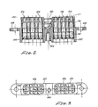
- Figure 1 shows one-half, cut at the longitudinal center line, of the wide side or the flat pack connector in a partial cross sectional view.
- Figure 1 shows receptacle part 100 electrically mated (engaged) with plug part 200.
- the large arrow MATE shows the direction of movement of the plug section 200 in order to mate with receptacle part 100.
- the large arrow LOCK shows the direction of movement of locking-unlocking means 300 to lock the parts 100 and 200 after mating.
- Receptacle part 100 includes a conductive metal housing 102.
- Housing 102 is capable of absorbing X-ray radiation and is thick enough to absorb a substantial amount of the X-ray radiation striking the exposed (open) surfaces of receptacle 100.
- Nickel, nickel alloy or nickel plated stainless steel are preferred.
- Receptacle 100 has a face 104, herein a flat face, having a number of perforations 106. Only two perforations are shown in Figure 1; a plurality of perforations are shown in Figure 2-5.
- Receptacle housing 102 is provided herein with two mounting ears 108 ( Figures 1-2).
- Receptacle housing face 104 is thick enough to cause X-ray radiation entering perforations 106, at an angle to face 104, to be shielded from striking the electrical contact pin sockets 110 position beneath perforations 106, i.e. the sockets are in the shadow of the perforations.
- Each pin socket 110 includes crimp barrel 112 for receiving an electrical lead, not shown, which lead connects the socket 110 to the electrical system of the vehicle, or other structure, to which the receptacle section 100 is attached.
- an electrical insulator 114 which includes X-ray radiation absorbent material is positioned inside housing 102, beneath face 104, enclosing sockets 110 lengthwise.
- This embodiment utilises two inserts, as shown in Figure 2.
- Figures 11-12 show an enlarged view of an insulator 114.
- each insert consists of three pieces 116,118 and 120 which will be described in more detail in connection with Figures 11-12.
- the extensions 117 ( Figures 1, 2 and 11) which insulate face 104 perforations from socket 110 and pin 206.
- plug part 200 includes a plug housing 202 having electrical contact pins 206 which include crimp barrels 208 surrounded by opening well 204 (see Figure 13). Crimp barrels 208 receive leads, not shown, for connecting by way of the mated pins and sockets of the connector the vehicle electrical system to an outside system.
- Plug housing 202 is made of conductive, X-ray absorbent, metal; the same metal may be used in the receptacle housing 102.
- the metal of housing 202 is capable of absorbing a substantial amount of X-ray radiation striking plug section 200.
- Insert 210 is positioned inside housing 202.
- insert 210 is made up of three pieces 212, 214 and 216.
- elastomer interface seal 218 positioned on the pin end of insert 210, which seal provides environmental protection to the pin openings 259 (see Figure 20) and socket openings 127 (see Figure 11) in inserts 210 and 114.
- Fluorosilicone rubber is a preferred material for the interface seal.
- Receptacle housing 102 is provided with a recess 130 for cooperation with said locking and unlocking means 300 to obtain and to maintain a locked relation of the two sections 100 and 200.
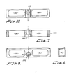
- Figures 4-6 show views of receptacle section 100 with two cutouts in Figure 4.
- One shows two perforations 106 in face 104 and insert 114. Looking down (toward face 104) at section line 5-5 reveals the view of Figure 5.
- the two inserts 114 show their socket openings 127, sized for two different contacts. Each opening is identified by numbers to aid in the insertion of contacts into the insert.
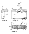
- Located in housing 102 is a threaded cavity 144.
- a backshell 146 is affixed to the rear end of housing 102 by way of bolt 148 threaded into cavity 144.
- Backshell 146 is provided with two elongated openings (conduits) affording electrical lead exit provisions from the inserts 114 ( Figure 4).
- Backshell 146 is provided with a central round passage 152 ( Figures 7-8) for bolt 148.
- Figure 9 is a cross-section showing one elongated side is inclined but this configuration is not essential.
- Figures 11-12 show one of the two inserts 114 used in connection with receptacle 100.
- Insert 114 is made up of three pieces 116,118 and 120. Each piece includes a number of cylindrical passages 126 whose size is determined by the dimensions of the particular pin socket and barrel. Two combinations appear in insert 114; six of one size and four of a smaller size ( Figure 12).
- Insert piece 116 is provided with tubular extensions 117 for insulating the metal face 104 from the pins 206, when in the mated relation.
- Insert piece 118 provides space in its opening 126 for elements which lock the pin socket 110 in place.
- Insert pieces 116 and 118 are preferably made of glass filled epoxy resin.
- Insert piece 120 is a grommet seal, preferably made of silicone rubber.
- a desirable safety feature is shown in Figure 5.
- the face 104 is rounded at two corners 105. Corresponding rounded corners in the mouth of the plug part result in an indexing feature which allows the two parts to fit together in only one unique manner.
- X-ray attenuation by inserts 114 is ensured by using X-ray radiation absorbent material e.g. a suitable metal powder can be used as a filler or part of the filler for the plastic material out of which the insert is formed.
- X-ray radiation absorbent material e.g. a suitable metal powder can be used as a filler or part of the filler for the plastic material out of which the insert is formed.
- X-ray radiation entering receptacle 100 parallel to perforations 106 will be absorbed in part by the socket. Should it be desirable to decrease the amount of such energy passing beyond the pin socket and reaching the electrical leads to the vehicle electrical system, suitable metal washers can be positioned below barrels 112 to intercept X-rays not absorbed earlier. Another expedient is to position a perforated metal plate (compression plate) beneath the insert 114 which plate aids in the attenuation of "parallel" X-rays and also further attenuate "angular" entry X-rays.
- compression plate compression plate
- Perforations 106 in face 104 are open to the entry of RFI energy when the connector has been disengaged and the plug section withdrawn.
- RFI energy can enter through the open perforations in the receptacle face into the interior of the receptacle, reach the electrical leads, and enter the on board electrical system. When this received energy is of sufficient magnitude, it causes malfunctions of the on board electrical system.
- the dimensions of said perforations 106 are selected to form wave traps (wave guides) having a cut off frequency above the frequency of radio frequency electromagnetic energy striking face 104 during operational use of receptacle 100.
- the reader is referred to Phillips U.S.A. Patent 3,550,065 for more detail on wave guides of this nature.
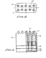
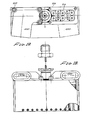
- FIG 13 shows a plan view in partial section of plug section 200 including locking-unlocking means 300.
- Plug housing 202 includes two plug inserts 210, consisting of insert pieces 212 and 214. These pieces 212 and 214 are preferably made of glass filled epoxy resin. Also insert piece 216 which is a grommet seal, preferably made of silicone rubber. An interface seal member 218, preferably made of fluorosilicone rubber, is positioned on the upper face of insert piece 212. Electrical pins 206, provided with crimp barrels 208 ( Figure 1) are fitted in passages 224 in said insert pieces and are tightly gripped by perforations in interface seal 218. Seal 218 is provided with edge portion 226 which edge aids in environmental sealing when the connector is in mated relation ( Figures 1 and 13).
- a cylindrical passage 230 in plug section 200 accommodates locking means 300.
- Plug housing 202 extends beyond interface seal 218 to form a walled well opening 204 and lip 205 extending around well 204. It is important that stray electromagnetic energy striking the two housings flows on by way of the housing rather than leak into the interior of the connector.
- the conductive contact between the exterior of housing 102, when mated, with the interior of opening 204 is improved by the presence of RFI fingers 240 mounted on all the four sides of opening 204 ( Figure 13).
- the RFI fingers 240 are manufactured in strips.
- the opening 204 is drilled around the lip 205 to permit flat flange eyelet fasteners 242, which hold the fingers 240 tightly against the wall of opening 204.
- the RFI fingers strips 240, retainers 244 and eyelets 242 are preferably made of gold plated beryllium copper alloy.
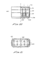
- the locations of RFI strips 240 are set out in Figure 13 and in Figure 17 where one looks into opening 204. To simplify the drawing, these RFI strips have been omitted from Figure 1.
- FIGs 15 through 19 show the plug backshell 248 which is affixed to lead exit end of the plug housing 202; the backshell 248 has a 90° turn away from the line of the plug housing.
- Each insert 210 has its exit conduit 250.
- Figure 17 is a view into opening 204 showing backshell conduits 250.
- Figure 18 is the same as Figure 15 but on a larger scale
- Figure 19 is on the same scale as Figure 18).
- Figure 19 gives a look down on backshell conduit 250-one is in a broken out view showing passage 230 and insert piece 216, three bolts 252 and three bolt holes 234.
- the plug housing, receptacle housing and the backshells are made of galvanic compatible metal and, preferably, are made of the same type of metal.
- Insert piece 216 is a grommet seal, preferably made from silicone rubber.
- Insert piece 212 is provided with outer shoulder 256 and a shallow rectangular indent 258 to better support interface seal 218. Shoulder 256 aids in positioning in 226 of seal 218 (see Figure 13).
- insert pieces 212 and 214 are made from glass filled epoxy resin.
- Locking-unlocking means 300 comprises, in combination: a tubular collet member 310 ( Figures 1 and 13) is provided with a number of collet fingers 312, each finger 312 terminates in a finger tip 314.
- Collet fingers 312 and finger tips 314 are capable of closing the fingers tips into a rough ball shape 316 ( Figure 17) and also opening to an expanded diameter, i.e., expanded with respect to the ball shape diameter.
- Collet 310 is a sliding fit in plug passage 230 (numeral shown in Figure 1).
- Collet 310 is retained in passage 230 by collar 320 positioned on the split tube of the collet fingers 312 behind the collet fingertips 314; collar 320 acts against the front face 231 of the plug housing wall establishing passage 230.
- Receptacle housing 102 includes recess 130, which is capable of receiving collet finger tips 314 and part of the lower end of collet fingers 312 and also accepts the fingertips 314 when expanded beyond the ball shape 316 ( Figure 17).
- the wall of recess 130 is provided with an annular protrusion 132 decreasing the internal diameter of recess 130 to just larger than that needed to pass the ball shape 316.
- Collet fingers 312 have a knuckle protrusion 315 extending outwardly enough to make contact with collar 320 closing the fingers and holding the plug in ready to mate position, (see Figure 13).
- recess 130 ends with a thickness of metal such that any EMI leakage into passage 230 and recess 130 is attenuated in both housings rather than entering the interior of the connector.
- collet fingers 312 are encircled by a helical spring 330 which fits between shoulder 318 of collet 310 and shoulder 235 of the wall of passage 230.
- a plunger rod 340 of a diameter capable of entering the empty space between the fingertips 314 in the ball position and expanding the fingertips is positioned inside collet 310.
- Plunger 340 is provided with a long hole, not shown, for receiving a lanyard cable end.
- Plunger 340 is one element in a lanyard assembly, not numbered.
- the lanyard assembly herein comprises: Plunger 340 ( Figures 1 and 13).
- Lanyard cable 350 is made of corrosion resistant steel cable.
- a stabiliser fitting 360 ( Figure 1) which rests on the rear end of plunger 340-the front of the locking means 300 is located at the collet fingertips 314.
- a lanyard guide 365 is supported by the rear end of collet 310.
- a plunger spring 370 is positioned and supported between stabiliser 360 and guide 365 ( Figure 1 and 13).
- a metal ball swaged about the lanyard cable 350 is located to permit affixing the lanyard to a solid surface by way of retaining nut 380 slidably positioned on the lanyard to the front of swage fitting 375. It is seen that lanyard 350 is affixed to plunger 340, passes through stabiliser 360, guide 365, retaining nut 380 and roughly terminates at swage fitting 375.
- the receptacle face 104 is lined up with plug opening 204 by the indexing means 105 and the two sections are pushed toward each other until a "mating line" 107 (see Figure 4), enscribed onto the receptacle housing exterior, disappears.
- the resistance of the pins entering the socket is great enough that the "mating line” is a valuable safety indicator of full mating. While the two parts are apparently solidly engaged after mating, vibrations and other movement of the connector can cause unmating and separation of the two parts.
- Locking means 300 is placed in operative position by having collet 310 in fully back location; at this location collet fingertips 314 are in the ball shape and a push on lanyard guide 365 forces collet 310 to move forward until the collet fingertips 314 pass beyond the annular protrusion 132 in receptacle recess 130.
- the collar 320 now is free of the knuckle protrusion 315.
- the plunger spring 370 forces the plunger 340 forward and cams the fingertips 314 to an expanded diameter greater than the internal diameter of protrusion 132. At this condition collet fingertips 314 cannot be withdrawn from recess 130 and the plug and receptacle sections are locked.
- a "locked line” is enscribed on the exterior of collet 310.
- These forward movements (indicated by the large arrow “lock” in Figure 1) also compress spring member 330.
- Compressed plunger spring 370 maintains the full forward position of plunger 340 and the expanded shape of the collet fingertips.
- the connector is unlocked and disengaged as follows: Lanyard cable 350 is pulled taut to overcome plunger spring 370, permitting plunger 340 to be withdrawn; this withdrawal permits the fingertips to retract into the ball shape.
- the unlocked connector halves are now free to separate under the load in lanyard 350.
- Compressed spring 330 forces the collet 310 and associated lanyard assembly rearward enough for the fingertips to clear protrusion 132, and the protrusion 315 strikes the collar 320 camming the collet end 314 closed which then prevents the plunger 340 from going forward. This positions the plug section in the ready to mate condition for the next mating.
- the herein described locking-unlocking means 300 has a safety feature. Should the collet 310 and guide 365 be pushed inwardly when the plug section is not engaged with the receptacle section, the plunger forces the fingertips into expanded configuration. The expanded fingertips cannot enter recess 130 fully and the two sections will not mate and no electrical continuity is made between contacts. Actually an immediate mismatch occurs and the operator is alerted to look for trouble, easily discernable by visual inspection of the plug pin opening, revealing the expanded fingertips.
Landscapes
- Details Of Connecting Devices For Male And Female Coupling (AREA)
Claims (11)
Applications Claiming Priority (2)
| Application Number | Priority Date | Filing Date | Title |
|---|---|---|---|
| US06/165,648 US4362348A (en) | 1980-07-03 | 1980-07-03 | EMI: X-Ray protected multi-contact connector |
| US165648 | 1980-07-03 |
Publications (2)
| Publication Number | Publication Date |
|---|---|
| EP0043636A1 EP0043636A1 (de) | 1982-01-13 |
| EP0043636B1 true EP0043636B1 (de) | 1985-07-10 |
Family
ID=22599836
Family Applications (1)
| Application Number | Title | Priority Date | Filing Date |
|---|---|---|---|
| EP81300763A Expired EP0043636B1 (de) | 1980-07-03 | 1981-02-24 | Gegen elektromagnetische Interferenz und Röntgenstrahlen geschützter Vielfachsteckverbinder |
Country Status (3)
| Country | Link |
|---|---|
| US (1) | US4362348A (de) |
| EP (1) | EP0043636B1 (de) |
| DE (1) | DE3171289D1 (de) |
Families Citing this family (17)
| Publication number | Priority date | Publication date | Assignee | Title |
|---|---|---|---|---|
| US4457574A (en) * | 1982-02-05 | 1984-07-03 | Automation Industries, Inc. | Electromagnetically shielded connector |
| DE3524137A1 (de) * | 1985-07-05 | 1987-01-15 | Thyssen Plastik Anger Kg | Steckverbindung |
| US4930209A (en) * | 1989-03-21 | 1990-06-05 | Amp Incorporated | Method for assembly of lanyard and connector |
| US5044975A (en) * | 1990-11-05 | 1991-09-03 | Ncr Corporation | Cable connector locking arrangement |
| US5315064A (en) * | 1991-11-08 | 1994-05-24 | William D. Piper | Suspended line breakaway device |
| GB9214523D0 (en) * | 1992-07-08 | 1992-08-19 | Amp Gmbh | An electrical connector with improved dampening means |
| US5387110A (en) * | 1993-11-12 | 1995-02-07 | International Business Machines Corporation | Reversible dual media adapter cable |
| US5411402A (en) * | 1993-12-17 | 1995-05-02 | Itt Corporation | Connector assembly for IC card |
| US5538437A (en) * | 1995-03-03 | 1996-07-23 | Itt Industries, Inc. | Connector assembly for IC card |
| US6494618B1 (en) | 2000-08-15 | 2002-12-17 | Varian Medical Systems, Inc. | High voltage receptacle for x-ray tubes |
| US6556654B1 (en) | 2001-11-09 | 2003-04-29 | Varian Medical Systems, Inc. | High voltage cable and clamp system for an X-ray tube |
| US6816574B2 (en) * | 2002-08-06 | 2004-11-09 | Varian Medical Systems, Inc. | X-ray tube high voltage connector |
| US7445517B2 (en) * | 2004-04-16 | 2008-11-04 | Varian Medical Systems, Inc. | High voltage cable assembly with ARC protection |
| US7150562B2 (en) * | 2004-09-09 | 2006-12-19 | Finisar Corporation | High voltage cable terminal and clamp system |
| US7134899B1 (en) * | 2005-11-21 | 2006-11-14 | George Ying-Liang Huang | Electrical connector assembly |
| FR2950205B1 (fr) * | 2009-09-11 | 2011-11-11 | Snecma | Dispositif de raccordement d'un capteur integre a un harnais electrique pour un moteur d'avion |
| DE102010042345A1 (de) * | 2010-10-12 | 2012-04-12 | Intercontec Pfeiffer Gmbh | Verfahren zum Verbinden von Steckerteilen eines elektrischen Steckverbinders sowie elektrischer Steckverbinder |
Family Cites Families (11)
| Publication number | Priority date | Publication date | Assignee | Title |
|---|---|---|---|---|
| US2762025A (en) * | 1953-02-11 | 1956-09-04 | Erich P Tilenius | Shielded cable connectors |
| DE1105940B (de) * | 1957-10-30 | 1961-05-04 | Souriau & Cie | Schnell zu trennende zweiteilige Steckverbindung, insbesondere fuer die Stromzufuehrung zu Raketen od. dgl. |
| DE1099031B (de) * | 1959-08-24 | 1961-02-09 | Licentia Gmbh | Steckervorrichtung eines elektrischen Vorort-Bohrgeraetes |
| GB979848A (en) * | 1961-03-04 | 1965-01-06 | English Electric Co Ltd | Improvements in and relating to electrical test couplings |
| US3288958A (en) * | 1965-02-11 | 1966-11-29 | Mark F Walther | Electromagentic radiation proof plug and receptacle |
| US3521222A (en) * | 1967-11-24 | 1970-07-21 | Bunker Ramo | Cable connector |
| US3550065A (en) * | 1968-01-11 | 1970-12-22 | G & H Technology | Electrical connector |
| US3594694A (en) * | 1968-11-08 | 1971-07-20 | G & H Technology | Quick disconnect connector |
| US4083619A (en) * | 1977-06-20 | 1978-04-11 | Automation Industries, Inc. | Electrical connector |
| US4148543A (en) * | 1978-04-28 | 1979-04-10 | General Dynamics Corporation | Suppressor for electromagnetic interference |
| US4202591A (en) * | 1978-10-10 | 1980-05-13 | Amerace Corporation | Apparatus for the remote grounding, connection and disconnection of high voltage electrical circuits |
-
1980
- 1980-07-03 US US06/165,648 patent/US4362348A/en not_active Expired - Lifetime
-
1981
- 1981-02-24 DE DE8181300763T patent/DE3171289D1/de not_active Expired
- 1981-02-24 EP EP81300763A patent/EP0043636B1/de not_active Expired
Also Published As
| Publication number | Publication date |
|---|---|
| EP0043636A1 (de) | 1982-01-13 |
| US4362348A (en) | 1982-12-07 |
| DE3171289D1 (en) | 1985-08-14 |
Similar Documents
| Publication | Publication Date | Title |
|---|---|---|
| EP0043636B1 (de) | Gegen elektromagnetische Interferenz und Röntgenstrahlen geschützter Vielfachsteckverbinder | |
| KR970004152B1 (ko) | 전기 접속기용 케이블 차폐 종단 장치 | |
| US4386819A (en) | RF Shielded assembly having capacitive coupling feature | |
| EP0024193B1 (de) | Im wesentlichen gegen elektromagnetische Impuls- und elektromagnetische Interferenzenergie abgeschirmter elektrischer Verbinder | |
| EP1803197B1 (de) | Elektrischer stecker und montageverfahren des steckers | |
| EP2311152B1 (de) | Elektrische verbindungsanordnung mit federbelastetem elektrischen verbinder | |
| US5170008A (en) | External cable grommet for cable entry of EMI protected cabinets | |
| US8251748B2 (en) | Connector assembly having a cavity sealing plug | |
| DE3604764A1 (de) | Elektrische steckverbindung | |
| GB2275832A (en) | Connector device | |
| US5012042A (en) | Cable entry device for EMI shielded cabinets | |
| CN108448311A (zh) | 满足ip68防护等级的单芯弯角连接器 | |
| JP2018041691A (ja) | 同軸コネクタ | |
| US10505309B2 (en) | Electrical device having a seal assembly | |
| US3167373A (en) | Multi-pin connector with protective shield | |
| EP0431206B1 (de) | Erdungssteckverbinder und Verfahren | |
| EP0326350A3 (de) | Steckervorrichtung für Koaxialkabel hoher Dichte | |
| US4514024A (en) | Shielded electrical connector | |
| US4399318A (en) | EMI Shielding enclosure for a cable connector | |
| US4693323A (en) | Flexible electromagnetic pulse shielding conduit | |
| US3052867A (en) | Electrical connector | |
| US5222899A (en) | Electrostatic discharge safety connector for electro-explosive devices | |
| EP0074159B1 (de) | Schutzhaube für eine schnellösbare elektrische Verbindung | |
| US3995930A (en) | High voltage tube connector | |
| US5421748A (en) | High-density, high-voltage-proof, multi-contact connector assembly |
Legal Events
| Date | Code | Title | Description |
|---|---|---|---|
| PUAI | Public reference made under article 153(3) epc to a published international application that has entered the european phase |
Free format text: ORIGINAL CODE: 0009012 |
|
| AK | Designated contracting states |
Designated state(s): BE DE FR GB IT NL SE |
|
| 17P | Request for examination filed |
Effective date: 19820707 |
|
| ITF | It: translation for a ep patent filed | ||
| GRAA | (expected) grant |
Free format text: ORIGINAL CODE: 0009210 |
|
| AK | Designated contracting states |
Designated state(s): BE DE FR GB IT NL SE |
|
| REF | Corresponds to: |
Ref document number: 3171289 Country of ref document: DE Date of ref document: 19850814 |
|
| ET | Fr: translation filed | ||
| PG25 | Lapsed in a contracting state [announced via postgrant information from national office to epo] |
Ref country code: SE Effective date: 19860225 |
|
| PG25 | Lapsed in a contracting state [announced via postgrant information from national office to epo] |
Ref country code: BE Effective date: 19860228 |
|
| PLBE | No opposition filed within time limit |
Free format text: ORIGINAL CODE: 0009261 |
|
| STAA | Information on the status of an ep patent application or granted ep patent |
Free format text: STATUS: NO OPPOSITION FILED WITHIN TIME LIMIT |
|
| 26N | No opposition filed | ||
| REG | Reference to a national code |
Ref country code: FR Ref legal event code: CD |
|
| BERE | Be: lapsed |
Owner name: AUTOMATION INDUSTRIES INC. Effective date: 19860228 |
|
| PG25 | Lapsed in a contracting state [announced via postgrant information from national office to epo] |
Ref country code: NL Effective date: 19860901 |
|
| GBPC | Gb: european patent ceased through non-payment of renewal fee | ||
| NLV4 | Nl: lapsed or anulled due to non-payment of the annual fee | ||
| PG25 | Lapsed in a contracting state [announced via postgrant information from national office to epo] |
Ref country code: FR Free format text: LAPSE BECAUSE OF NON-PAYMENT OF DUE FEES Effective date: 19861031 |
|
| PG25 | Lapsed in a contracting state [announced via postgrant information from national office to epo] |
Ref country code: DE Effective date: 19861101 |
|
| REG | Reference to a national code |
Ref country code: FR Ref legal event code: ST |
|
| PG25 | Lapsed in a contracting state [announced via postgrant information from national office to epo] |
Ref country code: GB Effective date: 19881118 |
|
| EUG | Se: european patent has lapsed |
Ref document number: 81300763.0 Effective date: 19861023 |