EP0043635B1 - Protective cover for electrical connector receptacle open end - Google Patents
Protective cover for electrical connector receptacle open end Download PDFInfo
- Publication number
- EP0043635B1 EP0043635B1 EP81300741A EP81300741A EP0043635B1 EP 0043635 B1 EP0043635 B1 EP 0043635B1 EP 81300741 A EP81300741 A EP 81300741A EP 81300741 A EP81300741 A EP 81300741A EP 0043635 B1 EP0043635 B1 EP 0043635B1
- Authority
- EP
- European Patent Office
- Prior art keywords
- barrel
- cover
- receptacle
- disc
- cover according
- Prior art date
- Legal status (The legal status is an assumption and is not a legal conclusion. Google has not performed a legal analysis and makes no representation as to the accuracy of the status listed.)
- Expired
Links
- 230000001681 protective effect Effects 0.000 title description 4
- 229920001971 elastomer Polymers 0.000 claims description 5
- 239000000806 elastomer Substances 0.000 claims description 5
- 230000014759 maintenance of location Effects 0.000 claims description 5
- 239000000463 material Substances 0.000 claims description 5
- 230000006835 compression Effects 0.000 claims description 4
- 238000007906 compression Methods 0.000 claims description 4
- 229910000906 Bronze Inorganic materials 0.000 claims description 3
- OAICVXFJPJFONN-UHFFFAOYSA-N Phosphorus Chemical compound [P] OAICVXFJPJFONN-UHFFFAOYSA-N 0.000 claims description 3
- 239000010974 bronze Substances 0.000 claims description 3
- KUNSUQLRTQLHQQ-UHFFFAOYSA-N copper tin Chemical compound [Cu].[Sn] KUNSUQLRTQLHQQ-UHFFFAOYSA-N 0.000 claims description 3
- 238000007789 sealing Methods 0.000 claims description 3
- 229920002379 silicone rubber Polymers 0.000 claims description 3
- 239000004945 silicone rubber Substances 0.000 claims description 3
- 239000002184 metal Substances 0.000 description 7
- 229910052751 metal Inorganic materials 0.000 description 7
- PXHVJJICTQNCMI-UHFFFAOYSA-N Nickel Chemical compound [Ni] PXHVJJICTQNCMI-UHFFFAOYSA-N 0.000 description 4
- -1 polyethylene Polymers 0.000 description 4
- 239000004033 plastic Substances 0.000 description 3
- 229920003023 plastic Polymers 0.000 description 3
- 229920002292 Nylon 6 Polymers 0.000 description 2
- 230000000694 effects Effects 0.000 description 2
- 229920005560 fluorosilicone rubber Polymers 0.000 description 2
- 239000003365 glass fiber Substances 0.000 description 2
- 239000007788 liquid Substances 0.000 description 2
- 229910052759 nickel Inorganic materials 0.000 description 2
- 230000000717 retained effect Effects 0.000 description 2
- 239000004698 Polyethylene Substances 0.000 description 1
- 230000002411 adverse Effects 0.000 description 1
- 239000004020 conductor Substances 0.000 description 1
- 238000010276 construction Methods 0.000 description 1
- 239000000428 dust Substances 0.000 description 1
- PCHJSUWPFVWCPO-UHFFFAOYSA-N gold Chemical compound [Au] PCHJSUWPFVWCPO-UHFFFAOYSA-N 0.000 description 1
- 239000010931 gold Substances 0.000 description 1
- 229910052737 gold Inorganic materials 0.000 description 1
- 238000009434 installation Methods 0.000 description 1
- 239000012811 non-conductive material Substances 0.000 description 1
- 230000035515 penetration Effects 0.000 description 1
- 229920000573 polyethylene Polymers 0.000 description 1
- 150000003839 salts Chemical class 0.000 description 1
- 239000007921 spray Substances 0.000 description 1
- 229910001220 stainless steel Inorganic materials 0.000 description 1
- 239000010935 stainless steel Substances 0.000 description 1
- 238000010998 test method Methods 0.000 description 1
- XLYOFNOQVPJJNP-UHFFFAOYSA-N water Substances O XLYOFNOQVPJJNP-UHFFFAOYSA-N 0.000 description 1
Images


Classifications
-
- H—ELECTRICITY
- H01—ELECTRIC ELEMENTS
- H01R—ELECTRICALLY-CONDUCTIVE CONNECTIONS; STRUCTURAL ASSOCIATIONS OF A PLURALITY OF MUTUALLY-INSULATED ELECTRICAL CONNECTING ELEMENTS; COUPLING DEVICES; CURRENT COLLECTORS
- H01R13/00—Details of coupling devices of the kinds covered by groups H01R12/70 or H01R24/00 - H01R33/00
- H01R13/44—Means for preventing access to live contacts
-
- H—ELECTRICITY
- H01—ELECTRIC ELEMENTS
- H01R—ELECTRICALLY-CONDUCTIVE CONNECTIONS; STRUCTURAL ASSOCIATIONS OF A PLURALITY OF MUTUALLY-INSULATED ELECTRICAL CONNECTING ELEMENTS; COUPLING DEVICES; CURRENT COLLECTORS
- H01R13/00—Details of coupling devices of the kinds covered by groups H01R12/70 or H01R24/00 - H01R33/00
- H01R13/46—Bases; Cases
- H01R13/52—Dustproof, splashproof, drip-proof, waterproof, or flameproof cases
Definitions
- This invention relates to multicontact electrical connectors.
- the invention relates to a protective cover for the receptacle open socket end of such a connector.
- the invention relates to such covers that can be constructed to provide RFI/EMI shielding.
- a protective cover is required for the receptacle open end when the receptacle and plug sections are not mated.
- these covers vary from simple polyethylene covers to metal covers of increasing complexity, covers which have multifingered conductive spring bands for RFI/EMI shielding; 0- rings or other types of gaskets for moisture proofing; threads or other forms of attachment and retainment.
- covers which have multifingered conductive spring bands for RFI/EMI shielding; 0- rings or other types of gaskets for moisture proofing; threads or other forms of attachment and retainment.
- Increasingly severe specifications have forced more and more complexity onto these covers.
- These more complex covers are not only heavy because they are made of metal but also they are expensive.
- the invention is aimed at attaining some or all of these objects.
- a cover for a cylindrical electrical connector receptacle open socket end comprising:
- the barrel is made up of at least two wall portions, one of which includes said locating means.
- said elastomer member is made from silicone rubber; preferably said member is fluorosilicone rubber for aircraft usage of said cover.
- the spring means includes a plurality of conical coil compression springs.
- the plate for closing the other end of said barrel may include an exterior handle. The plate may be a unitary construction with the barrel or a portion of the barrel.
- the cover body (barrel plus plate) is made of non-conductive, rigid plastic, such as, glass fibre filled nylon 6/6.
- the disc is made of metal, such as, nickel plated phosphor bronze, to provide RFI/EMI shielding.
- the locating means are keyways affording unique alignment with keys located on said receptacle socket end and means operative with said keys for retainment of, and for locking, said barrel to said receptacle open socket.
- Fig. 1 is a schematic isometric, with a partial cross section, of one embodiment of this invention.
- Cover 20 comprises a unitary barrel 22 having an open end 24.
- a plate means 28 closes the other end of barrel 22.
- Plate 28 includes a handle 30, here a foldable handle in a cavity to retain a plane surface, with hinge pin 32 and a captive screw 34 for locking the handle 30 in the cavity.
- the exterior of barrel 22 has an annular recess 36 for maintaining in place sealing 0-ring 38.
- Fig. 1 has a unitary barrel 22 and plate 28 constructed of moulded hard, more or less rigid, plastic material. Such a unitary constructed is denoted a cover body. At the open end 24 of barrel 22, locating means afford a unique alignment of the cover 20 with particular receptacle open socket end which is to be covered by cover 20.
- Fig. 1 shows two of the three keyways 42 which, in cooperation with keys on the exterior of said receptacle open end enable correct location or polarisation of the cover with respect to the socket.
- a disc 54 has a controlled longitudinal travel inside barrel 22.
- Disc 54 is controlled in its travel by keeper ring 56 positioned in an annular cut, not numbered, in the barrel.
- keeper ring 56 positioned in an annular cut, not numbered, in the barrel.
- cover 20 is in place on said receptacle open end
- disc 54 is held in tight contact with said receptacle open end by a plurality of conical coil compression springs 60 positioned underneath disc 54, and abutted in cavities in the inside surface of cover plate 28.
- the travel of disc 54, urged by spring means 60 is controlled to apply pressure to said receptacle socket open end, to maintain retainment of said cover on said receptacle and to lock said cover to said open receptacle open socket.
- the barrel 22 and plate 28 are preferably made of non-conductive (insulating) more or less rigid plastic material.
- a preferred material is glass fibre filled nylon 6/6.
- the seal gasket 38, herein an O-ring, is desirably made of elastomer material, such as, silicone rubber; especially fluorosilicone rubber.
- Disc 54 may be non-conductive material when RFI/EMI shielding is not'essential. For RFI/EMI shielding, disc 54 is made of conductive material; preferably nickel plated phosphor bronze with a gold flash finish.
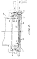
- Fig. 2 shows the preferred embodiment of the cover of this invention.
- the body 70 is made up of two separate pieces; the body cover top 72 (includes the plate) and body cover bottom 74 (includes indexing means).
- the barrel 80 which comprises body bottom 74 and wall extension 82 of body 72 is fashioned to have plate 84 slope at the aerodynamic profile of the underneath side of the aircraft wing to which receptacle socket 90 is attached, i.e., the profile (contour) of the wing matches the profile of the cover plate.
- lip 85 rides against the lower end of keys 92 to retain the cover on the receptacle socket.
- Spring means 88 force disc 89 into intimate contact with receptacle open socket end 94 not only resulting in good electrical contact, with a metal disc, but also locking the cover and receptacle together (capture and maintain the receptacle key in the barrel detent).
- the intimate contact of disc 89 with the entire front face of the end of the receptacle socket opening in effect encloses all the electrical elements, such as the receptacle socket contacts, which are susceptible to RFI/EMI, in a metal shield, thereby negating the need for a metal cover housing and fingered bands as used in other protective covers.
- 0-ring 87 located in annular recess 86, seals the cover the receptacle from penetration by either liquid water or atmospheric humidity.
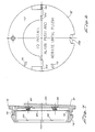
- Figs. 3-3E are directed to the body bottom 74 (barrel portion which includes the locating means).
- Fig. 3 shows 3 keyways 100 and the angular spacing for this embodiment of the keyway. Also there are shown 6 detents (anti-rotation notches) 102 and their angular spacing.
- Figs. 3B and 3E show different views of a keyway at "B" on Fig. 3.
- Fig. 3D is a view of a detent at D-D on Fig. 3.
- Fig. 3C shows a keyway at C-C on Fig. 3.
- Fig. 3A is a cross section of Fig. 3 at A-A showing a keyway and two detents.
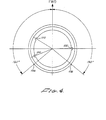
- Fig. 4 shows the three keyways 100 and two cover plate profile location positions 106 for this embodiment, at 103° from the FWD position.
- the cover plate profile location permits positioning with respect to the particular wing profile.
- the wing profiles varies from right ring to left wing by 100°. This position is maintained until manually removed by the handle 110, which handle stows flush during flight.
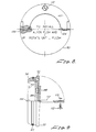
- Fig. 5 shows a plan view of body cover top 72, handle 110, and captive screw 112 with arrows 116 for locating the keyways 100 in barrel portion 74.
- Spring retention cavities 120 on the inside of plate 72 are shown in dashed lines.
- Fig. 6 is another view of plate 72 showing hinge pins 124 for handle 110, desirably made of stainless steel. Indexing buttons 128 are spaced 180° apart. During the bonding of the cover, buttons 128 register the top half of the body to the bottom half thereoof.
- Fig. 7 has somewhat more detail than Fig. 2.
- Fig. 7 shows body 70, omitting the handle 110, formed of two pieces: the body cover top 72 and body cover bottom 74.
- Plate 84 is more clearly evident as having an aerodynamic profile matching the wing profile.
- Spring means 88 force disc 89 upward with a restraint shoulder 75 formed by body cover bottom 74.
- Annular recess 86 admits 0-ring 87 (Fig. 2).
- Various spring means can be used to maintain pressure on the disc. Because of their ability to compress into a thin flat dimension upwardly, the conical coil depression springs are preferred. It is intended that all those springs which perform like the conical coil compressing spring are included in the use of that name, for example, the single and double volute springs.
- Fig. 8 is another view of the plate 70 showing handle 110, hinge pins 124, and hinge 126.
- Fig. 9 shows more detail of cover 70 showing O-ring 87 in place.
- Handle 110 is in the extended position with captive screw 112 removed from the handle and retaining ring 113 on the side of handle 110.
- Fig. 10 is another view of cover 70 with handle 110 extended, showing hinge pins 124 and hinge 126; also spring means 88 pushing disc 89 against shoulder 75, and 0-ring 87 in annular recess 86. Three detents 102 and 2 keyways 100 are shown.
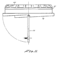
- Fig. 11 is a side view of the cover with handle extended.
- Body cover bottom 74 is reinforced on the exterior by a plurality of ribs 140.
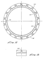
- Figs. 12-13 are a top view and side view, respectively, of two ribs 140 of bottom 74 show detail of ribs 140 and keyway 100.
- the purpose of ribs 140 is to reduce heavy cross sectional molded area to achieve a more uniform wall section and to prevent distortion of the molded part.
- Fig. 14 is another top view of bottom 74 showing ribs 140, keyways 100, and detents 102, in dashed lines.
- the disc is forced to turn with the rotation of barrel as the cover is brought into indexed relation with receptacle open end, and rotated to the detents controlling the particular wing profile.
- This movement with the barrel aids in forcing intimate electrical contact of the disc and receptacle open end.
- the inside of the barrel is provided with a longitudinal arcuate protrusion and the disc is notched to accept the barrel protrusion.
- the cover is oriented by aligning the keyways with the keys on the exterior wall of the receptacle open end.
- the non-conductive, rigid cover overcoming the spring resistance, is forced upward (big arrow in Fig. 2) until the barrel lip extends beyond the top of the keys and the metal disc is in contact with end 94 of the receptacle.
- handle 110 is rotated in the direction required to have the plate profile match the wing profile, forcing the spring loaded disc into intimate contact with receptacle end 94, which permits retainment of cover and receptacle.
- the cover and receptacle are locked together by further rotation which meshes the keys into detents 102.
- 0-ring 87 seals against the receptacle cavity and precludes entrance of moisture.
- Handle 110 is returned to its cavity and is retained by screw 112.
Description
- This invention relates to multicontact electrical connectors. Particularly the invention relates to a protective cover for the receptacle open socket end of such a connector. Especially, the invention relates to such covers that can be constructed to provide RFI/EMI shielding.
- In the case of aircraft wing installations electrical connectors present a special problem when only the receptacle section is present, that is, when the plug section is not needed for a particular flight. The open socket end of the receptacle permits air flow buffeting of the socket contacts, and, especially harmful, exposes the internal airfract circuitry, connected to the receptacle, to RFI/EMI effects coming in through the open end of the socket contacts; also it permits entry of rain, dust, or simple humidity into the socket open end of the receptacle.
- In most instances, a protective cover is required for the receptacle open end when the receptacle and plug sections are not mated. Depending on the degree of protection required these covers vary from simple polyethylene covers to metal covers of increasing complexity, covers which have multifingered conductive spring bands for RFI/EMI shielding; 0- rings or other types of gaskets for moisture proofing; threads or other forms of attachment and retainment. Increasingly severe specifications have forced more and more complexity onto these covers. These more complex covers are not only heavy because they are made of metal but also they are expensive.
- At the present time the most sophisticated covers for the receptacle open socket end are required to meet most of, and desirably all of the following:
- 1. The buffeting and stresses when used on fighter aircraft.
- 2. The cover should provide an aerodynamic profile, especially when used on fighter aircraft wings.
- 3. The cover should when necessary shield against entry of exiting of RFI/EMI.
- 4. The cover should seal against entry of moisture, both liquid (rain) and humidity.
- 5. The cover should withstand the ravages of e.g. five hundred (500) hours continuous exposure to salt spray in a defined test procedure.
- 6. The cover should attach to and be retained with (locked to) the unmated open socket end of the receptacle, which receptacle is mounted in a cavity on the underneath side of the wing.
- 7. The cover should be light in weight.
- 8. The cover should be cost effective (inexpensive even though having large benefits).
- It is evident that several of the above requirements apply to other situations, such as, ships and boats; motor vehicles; railway vehicles; exteriors of building in adverse environments, desert and sea shore.
- The invention is aimed at attaining some or all of these objects.
- According to the invention there is provided a cover for a cylindrical electrical connector receptacle open socket end comprising:
- a barrel having locating means at an open end thereof for unique alignment with a receptacle open socket; means for retention of said barrel at said open socket end; and
- a plate for closing the other end of said barrel, characterised in that:
- the cover includes an elastomer member positioned on the exterior of said barrel for sealing contact with said receptacle open socket end,
- said retention means includes a disc which contacts said open socket end and which is movable axially along the barrel, means for controlling the distance of travel of said disc, and spring means acting between the disc and the plate.
- Preferably, the barrel is made up of at least two wall portions, one of which includes said locating means. Desirably said elastomer member is made from silicone rubber; preferably said member is fluorosilicone rubber for aircraft usage of said cover. Preferably the spring means includes a plurality of conical coil compression springs. The plate for closing the other end of said barrel may include an exterior handle. The plate may be a unitary construction with the barrel or a portion of the barrel.
- Preferably the cover body (barrel plus plate) is made of non-conductive, rigid plastic, such as, glass fibre filled nylon 6/6. Preferably the disc is made of metal, such as, nickel plated phosphor bronze, to provide RFI/EMI shielding.
- In a preferred embodiment, the locating means are keyways affording unique alignment with keys located on said receptacle socket end and means operative with said keys for retainment of, and for locking, said barrel to said receptacle open socket.
- Embodiments of the invention are hereafter described with reference to the accompanying drawings, in which:-
- Fig. 1 is a schematic view in partial cross section of one embodiment of the cover of the invention.
- Fig. 2 is a cross section plan view of a cover of the invention attached to the open socket end of a receptacle section, shown in phantom lines.
- Fig. 3 is a view looking up into the interior of the open end of the cover barrel (also denoted "body-cover bottom").
- Fig. 3A is a cross sectional side view at A-A of Fig. 3, showing detents and a keyway.
- Figs. 3B-E are partial views of Fig. 3 at the designated locations of detent or keyway.
- Fig. 4 shows one arrangement of three keyways for locating with keys on the exterior of a particular receptacle socket opening, where FWD means forward.
- Fig. 5 is a view of the cover plate showing the fold down handle, indicators for three keyways, and dotted cavities for eight conical coil compression springs.
- Fig. 6 is another view of the cover plate showing hinge pins for the handle.
- Fig. 7 is a cross section of the cover showing the springs and disc.
- Fig. 8 is another view of the cover plate showing a detail of one handle hinge.
- Fig: 9 shows a side view, in partial cross section with handle extended and one-type of retaining screw.
- Fig. 10 is another partial cross sectional side view of the cover with extended handle.
- Fig. 11 is a side view of the cover with extended handle.
- Fig. 12 is a bottom view of the barrel.
- Fig. 13 is a detail of Fig. 12 in a side view.
- Fig. 14 is another bottom view of the barrel emphasising the three keyways and dotted lines showing the location of the six detents in this embodiment.
- In the figures, Fig. 1 is a schematic isometric, with a partial cross section, of one embodiment of this invention.
Cover 20 comprises aunitary barrel 22 having anopen end 24. A plate means 28 closes the other end ofbarrel 22.Plate 28 includes ahandle 30, here a foldable handle in a cavity to retain a plane surface, withhinge pin 32 and acaptive screw 34 for locking thehandle 30 in the cavity. The exterior ofbarrel 22 has anannular recess 36 for maintaining in place sealing 0-ring 38. - The embodiment of Fig. 1 has a
unitary barrel 22 andplate 28 constructed of moulded hard, more or less rigid, plastic material. Such a unitary constructed is denoted a cover body. At theopen end 24 ofbarrel 22, locating means afford a unique alignment of thecover 20 with particular receptacle open socket end which is to be covered bycover 20. Fig. 1 shows two of the threekeyways 42 which, in cooperation with keys on the exterior of said receptacle open end enable correct location or polarisation of the cover with respect to the socket. Also at theopen end 24, there are means 46 for retainment ofbarrel 22 at said receptacle open socket end, i.e., thecover 20, through annular lip 48 anddetents 50, meshes with keys on the exterior of the receptacle end to lock together securely the cover and the receptacle. - In Fig. 1 a
disc 54 has a controlled longitudinal travel insidebarrel 22.Disc 54 is controlled in its travel bykeeper ring 56 positioned in an annular cut, not numbered, in the barrel. Whencover 20 is in place on said receptacle open end,disc 54 is held in tight contact with said receptacle open end by a plurality of conical coil compression springs 60 positioned underneathdisc 54, and abutted in cavities in the inside surface ofcover plate 28. The travel ofdisc 54, urged by spring means 60, is controlled to apply pressure to said receptacle socket open end, to maintain retainment of said cover on said receptacle and to lock said cover to said open receptacle open socket. - The
barrel 22 andplate 28 are preferably made of non-conductive (insulating) more or less rigid plastic material. A preferred material is glass fibre filled nylon 6/6. Theseal gasket 38, herein an O-ring, is desirably made of elastomer material, such as, silicone rubber; especially fluorosilicone rubber.Disc 54 may be non-conductive material when RFI/EMI shielding is not'essential. For RFI/EMI shielding,disc 54 is made of conductive material; preferably nickel plated phosphor bronze with a gold flash finish. - Fig. 2 shows the preferred embodiment of the cover of this invention. Here it is seen that the
body 70 is made up of two separate pieces; the body cover top 72 (includes the plate) and body cover bottom 74 (includes indexing means). It is also seen that thebarrel 80, which comprises body bottom 74 andwall extension 82 ofbody 72 is fashioned to haveplate 84 slope at the aerodynamic profile of the underneath side of the aircraft wing to whichreceptacle socket 90 is attached, i.e., the profile (contour) of the wing matches the profile of the cover plate. - Here
lip 85 rides against the lower end ofkeys 92 to retain the cover on the receptacle socket. Spring means 88force disc 89 into intimate contact with receptacleopen socket end 94 not only resulting in good electrical contact, with a metal disc, but also locking the cover and receptacle together (capture and maintain the receptacle key in the barrel detent). The intimate contact ofdisc 89 with the entire front face of the end of the receptacle socket opening in effect encloses all the electrical elements, such as the receptacle socket contacts, which are susceptible to RFI/EMI, in a metal shield, thereby negating the need for a metal cover housing and fingered bands as used in other protective covers. - 0-
ring 87, located inannular recess 86, seals the cover the receptacle from penetration by either liquid water or atmospheric humidity. - Figs. 3-3E are directed to the body bottom 74 (barrel portion which includes the locating means). Fig. 3 shows 3
keyways 100 and the angular spacing for this embodiment of the keyway. Also there are shown 6 detents (anti-rotation notches) 102 and their angular spacing. Figs. 3B and 3E show different views of a keyway at "B" on Fig. 3. Fig. 3D is a view of a detent at D-D on Fig. 3. Fig. 3C shows a keyway at C-C on Fig. 3. Fig. 3A is a cross section of Fig. 3 at A-A showing a keyway and two detents. - Fig. 4 shows the three
keyways 100 and two cover plateprofile location positions 106 for this embodiment, at 103° from the FWD position. The cover plate profile location permits positioning with respect to the particular wing profile. Here the wing profiles varies from right ring to left wing by 100°. This position is maintained until manually removed by thehandle 110, which handle stows flush during flight. - Fig. 5 shows a plan view of body cover top 72, handle 110, and
captive screw 112 witharrows 116 for locating thekeyways 100 inbarrel portion 74.Spring retention cavities 120 on the inside ofplate 72 are shown in dashed lines. - Fig. 6 is another view of
plate 72 showing hinge pins 124 forhandle 110, desirably made of stainless steel.Indexing buttons 128 are spaced 180° apart. During the bonding of the cover,buttons 128 register the top half of the body to the bottom half thereoof. - Fig. 7 has somewhat more detail than Fig. 2. Fig. 7 shows
body 70, omitting thehandle 110, formed of two pieces: thebody cover top 72 and body cover bottom 74.Plate 84 is more clearly evident as having an aerodynamic profile matching the wing profile. Spring means 88force disc 89 upward with arestraint shoulder 75 formed by body cover bottom 74.Annular recess 86 admits 0-ring 87 (Fig. 2). Various spring means can be used to maintain pressure on the disc. Because of their ability to compress into a thin flat dimension upwardly, the conical coil depression springs are preferred. It is intended that all those springs which perform like the conical coil compressing spring are included in the use of that name, for example, the single and double volute springs. - Fig. 8 is another view of the
plate 70 showinghandle 110, hinge pins 124, and hinge 126. Fig. 9 shows more detail ofcover 70 showing O-ring 87 in place. Handle 110 is in the extended position withcaptive screw 112 removed from the handle and retainingring 113 on the side ofhandle 110. - Fig. 10 is another view of
cover 70 withhandle 110 extended, showing hinge pins 124 and hinge 126; also spring means 88 pushingdisc 89 againstshoulder 75, and 0-ring 87 inannular recess 86. Threedetents 102 and 2keyways 100 are shown. - Fig. 11 is a side view of the cover with handle extended. Body cover bottom 74 is reinforced on the exterior by a plurality of
ribs 140. Figs. 12-13 are a top view and side view, respectively, of tworibs 140 of bottom 74 show detail ofribs 140 andkeyway 100. The purpose ofribs 140 is to reduce heavy cross sectional molded area to achieve a more uniform wall section and to prevent distortion of the molded part. - Fig. 14 is another top view of bottom 74 showing
ribs 140,keyways 100, anddetents 102, in dashed lines. - Desirably the disc is forced to turn with the rotation of barrel as the cover is brought into indexed relation with receptacle open end, and rotated to the detents controlling the particular wing profile. This movement with the barrel aids in forcing intimate electrical contact of the disc and receptacle open end. Preferably, the inside of the barrel is provided with a longitudinal arcuate protrusion and the disc is notched to accept the barrel protrusion.
- In use, the cover is oriented by aligning the keyways with the keys on the exterior wall of the receptacle open end. The non-conductive, rigid cover, overcoming the spring resistance, is forced upward (big arrow in Fig. 2) until the barrel lip extends beyond the top of the keys and the metal disc is in contact with
end 94 of the receptacle. Then handle 110 is rotated in the direction required to have the plate profile match the wing profile, forcing the spring loaded disc into intimate contact withreceptacle end 94, which permits retainment of cover and receptacle. Then the cover and receptacle are locked together by further rotation which meshes the keys intodetents 102. 0-ring 87 seals against the receptacle cavity and precludes entrance of moisture. Handle 110 is returned to its cavity and is retained byscrew 112.
Claims (8)
Applications Claiming Priority (2)
| Application Number | Priority Date | Filing Date | Title |
|---|---|---|---|
| US06/165,722 US4385792A (en) | 1980-07-03 | 1980-07-03 | Protective cover for electrical connector receptacle open end, providing RFI/EMI shielding |
| US165722 | 1980-07-03 |
Publications (2)
| Publication Number | Publication Date |
|---|---|
| EP0043635A1 EP0043635A1 (en) | 1982-01-13 |
| EP0043635B1 true EP0043635B1 (en) | 1984-11-07 |
Family
ID=22600173
Family Applications (1)
| Application Number | Title | Priority Date | Filing Date |
|---|---|---|---|
| EP81300741A Expired EP0043635B1 (en) | 1980-07-03 | 1981-02-23 | Protective cover for electrical connector receptacle open end |
Country Status (3)
| Country | Link |
|---|---|
| US (1) | US4385792A (en) |
| EP (1) | EP0043635B1 (en) |
| DE (1) | DE3167018D1 (en) |
Families Citing this family (9)
| Publication number | Priority date | Publication date | Assignee | Title |
|---|---|---|---|---|
| GB2165403A (en) * | 1984-10-05 | 1986-04-09 | Jnr James George Hickmott | A safety guard for electrical plugs |
| US4836794A (en) * | 1988-08-05 | 1989-06-06 | Kern Engineering & Mfg. Corp. | EMI and environmentally protected connector cap |
| US5030118A (en) * | 1990-02-28 | 1991-07-09 | The United States Of America As Represented By The Secretary Of The Air Force | Retractable connector protective cover |
| US5211582A (en) * | 1992-03-09 | 1993-05-18 | Amphenol Corporation | Repairable connector |
| US5936202A (en) * | 1997-07-10 | 1999-08-10 | Mcdonnell Douglas Corporation | Debris protection cover assembly for cable connectors |
| US20030156412A1 (en) * | 2002-02-19 | 2003-08-21 | Limber Jamie A. | Safety cap for light strings |
| US7287992B2 (en) * | 2005-10-28 | 2007-10-30 | John Mezzalingua Associates, Inc. | Protective cap for coaxial cable port terminator |
| US9242521B2 (en) | 2012-01-25 | 2016-01-26 | John R. Columbia | Multi-function hitch accessory retaining device and method |
| DE102019002346A1 (en) * | 2019-03-29 | 2020-10-01 | Yamaichi Electronics Deutschland Gmbh | Universal Closure Cap, Use, Closure System and Procedure |
Family Cites Families (5)
| Publication number | Priority date | Publication date | Assignee | Title |
|---|---|---|---|---|
| US3176257A (en) * | 1963-03-08 | 1965-03-30 | Cole Hersee Company | Bracket for holding trailer plugs of tractor-trailer vehicles |
| US3182280A (en) * | 1963-04-19 | 1965-05-04 | Francis X Daut | Protection of electrical connector contact pins |
| US3327279A (en) * | 1964-09-11 | 1967-06-20 | Charles J Lombard | Plug |
| US3794956A (en) * | 1972-06-30 | 1974-02-26 | R Dubreuil | Recessible electric floor or the like outlet assembly |
| DE2840696C2 (en) * | 1978-09-19 | 1982-05-06 | Aloys Mennekes Anlagengesellschaft, 5942 Kirchhundem | Protective cover with locking lock for a collar plug |
-
1980
- 1980-07-03 US US06/165,722 patent/US4385792A/en not_active Expired - Lifetime
-
1981
- 1981-02-23 DE DE8181300741T patent/DE3167018D1/en not_active Expired
- 1981-02-23 EP EP81300741A patent/EP0043635B1/en not_active Expired
Also Published As
| Publication number | Publication date |
|---|---|
| DE3167018D1 (en) | 1984-12-13 |
| EP0043635A1 (en) | 1982-01-13 |
| US4385792A (en) | 1983-05-31 |
Similar Documents
| Publication | Publication Date | Title |
|---|---|---|
| EP0043635B1 (en) | Protective cover for electrical connector receptacle open end | |
| US4597620A (en) | Electrical connector and method of using it | |
| US3740981A (en) | Closure device for locks | |
| US6910905B2 (en) | Waterproof connector | |
| DE102018101213A1 (en) | Replaceable battery for an electrically driven watercraft | |
| US20100190375A1 (en) | Connector receptacle with molded front nut gasket | |
| US5046964A (en) | Hybrid connector | |
| US7226692B2 (en) | Battery lock | |
| US4330166A (en) | Electrical connector substantially shielded against EMP and EMI energy | |
| US20070173112A1 (en) | Connector | |
| CA2096710A1 (en) | Connector for Armored Electrical Cable | |
| US4638652A (en) | Sealing cap | |
| DE3248715A1 (en) | ELECTRICAL SWITCHGEAR, ESPECIALLY FOR MOTOR VEHICLES | |
| WO2007032816A2 (en) | A connector for harsh environments | |
| AU2004298276B2 (en) | Single battery housing assembly | |
| CN111418199B (en) | Protective shell structure, handheld cloud platform and shooting equipment | |
| EP0103787A1 (en) | Electrical connectors with protective hood | |
| US4630877A (en) | Socket | |
| US4836794A (en) | EMI and environmentally protected connector cap | |
| EP0163064A3 (en) | Electrical connector assembly having locking means | |
| CN112290279B (en) | Connector with a locking member | |
| EP0074159B1 (en) | Shielded cover for a quick-release electrical connector | |
| US11079659B2 (en) | Sliding cover with inclined-plane seal for weather sealed consumer electronics device | |
| US6435910B1 (en) | Sealed electrical distribution centers | |
| US3469044A (en) | Rotary make-up electrical connector for underwater use |
Legal Events
| Date | Code | Title | Description |
|---|---|---|---|
| PUAI | Public reference made under article 153(3) epc to a published international application that has entered the european phase |
Free format text: ORIGINAL CODE: 0009012 |
|
| AK | Designated contracting states |
Designated state(s): BE DE FR GB IT NL SE |
|
| 17P | Request for examination filed |
Effective date: 19820611 |
|
| ITF | It: translation for a ep patent filed |
Owner name: JACOBACCI & PERANI S.P.A. |
|
| GRAA | (expected) grant |
Free format text: ORIGINAL CODE: 0009210 |
|
| AK | Designated contracting states |
Designated state(s): BE DE FR GB IT NL SE |
|
| PGFP | Annual fee paid to national office [announced via postgrant information from national office to epo] |
Ref country code: FR Payment date: 19841126 Year of fee payment: 5 |
|
| REF | Corresponds to: |
Ref document number: 3167018 Country of ref document: DE Date of ref document: 19841213 |
|
| ET | Fr: translation filed | ||
| PGFP | Annual fee paid to national office [announced via postgrant information from national office to epo] |
Ref country code: BE Payment date: 19841231 Year of fee payment: 5 |
|
| PGFP | Annual fee paid to national office [announced via postgrant information from national office to epo] |
Ref country code: NL Payment date: 19850228 Year of fee payment: 5 |
|
| PLBE | No opposition filed within time limit |
Free format text: ORIGINAL CODE: 0009261 |
|
| STAA | Information on the status of an ep patent application or granted ep patent |
Free format text: STATUS: NO OPPOSITION FILED WITHIN TIME LIMIT |
|
| 26N | No opposition filed | ||
| PG25 | Lapsed in a contracting state [announced via postgrant information from national office to epo] |
Ref country code: SE Effective date: 19860224 |
|
| PG25 | Lapsed in a contracting state [announced via postgrant information from national office to epo] |
Ref country code: BE Effective date: 19860228 |
|
| REG | Reference to a national code |
Ref country code: FR Ref legal event code: CD |
|
| BERE | Be: lapsed |
Owner name: AUTOMATION INDUSTRIES INC. Effective date: 19860228 |
|
| PG25 | Lapsed in a contracting state [announced via postgrant information from national office to epo] |
Ref country code: NL Effective date: 19860901 |
|
| NLV4 | Nl: lapsed or anulled due to non-payment of the annual fee | ||
| PG25 | Lapsed in a contracting state [announced via postgrant information from national office to epo] |
Ref country code: FR Free format text: LAPSE BECAUSE OF NON-PAYMENT OF DUE FEES Effective date: 19861031 |
|
| PG25 | Lapsed in a contracting state [announced via postgrant information from national office to epo] |
Ref country code: DE Effective date: 19861101 |
|
| REG | Reference to a national code |
Ref country code: FR Ref legal event code: ST |
|
| REG | Reference to a national code |
Ref country code: GB Ref legal event code: 732 |
|
| PGFP | Annual fee paid to national office [announced via postgrant information from national office to epo] |
Ref country code: GB Payment date: 19890228 Year of fee payment: 9 |
|
| PG25 | Lapsed in a contracting state [announced via postgrant information from national office to epo] |
Ref country code: GB Effective date: 19900223 |
|
| GBPC | Gb: european patent ceased through non-payment of renewal fee | ||
| EUG | Se: european patent has lapsed |
Ref document number: 81300741.6 Effective date: 19861023 |