EP0103787A1 - Electrical connectors with protective hood - Google Patents
Electrical connectors with protective hood Download PDFInfo
- Publication number
- EP0103787A1 EP0103787A1 EP83108563A EP83108563A EP0103787A1 EP 0103787 A1 EP0103787 A1 EP 0103787A1 EP 83108563 A EP83108563 A EP 83108563A EP 83108563 A EP83108563 A EP 83108563A EP 0103787 A1 EP0103787 A1 EP 0103787A1
- Authority
- EP
- European Patent Office
- Prior art keywords
- hood
- connector
- sidewall
- end portion
- cavity
- Prior art date
- Legal status (The legal status is an assumption and is not a legal conclusion. Google has not performed a legal analysis and makes no representation as to the accuracy of the status listed.)
- Granted
Links
- 230000001681 protective effect Effects 0.000 title claims abstract description 19
- 239000000463 material Substances 0.000 claims description 9
- 230000000295 complement effect Effects 0.000 claims description 5
- 239000004020 conductor Substances 0.000 description 21
- 229920003023 plastic Polymers 0.000 description 6
- 230000013011 mating Effects 0.000 description 4
- 239000002184 metal Substances 0.000 description 2
- 238000000034 method Methods 0.000 description 2
- 239000012811 non-conductive material Substances 0.000 description 2
- 238000012360 testing method Methods 0.000 description 2
- 230000008878 coupling Effects 0.000 description 1
- 238000010168 coupling process Methods 0.000 description 1
- 238000005859 coupling reaction Methods 0.000 description 1
- 229920002457 flexible plastic Polymers 0.000 description 1
- 231100001261 hazardous Toxicity 0.000 description 1
- 238000009434 installation Methods 0.000 description 1
- 238000012423 maintenance Methods 0.000 description 1
- 238000003825 pressing Methods 0.000 description 1
- 239000000523 sample Substances 0.000 description 1
- 229910000679 solder Inorganic materials 0.000 description 1
Images

Classifications
-
- H—ELECTRICITY
- H01—ELECTRIC ELEMENTS
- H01R—ELECTRICALLY-CONDUCTIVE CONNECTIONS; STRUCTURAL ASSOCIATIONS OF A PLURALITY OF MUTUALLY-INSULATED ELECTRICAL CONNECTING ELEMENTS; COUPLING DEVICES; CURRENT COLLECTORS
- H01R13/00—Details of coupling devices of the kinds covered by groups H01R12/70 or H01R24/00 - H01R33/00
- H01R13/46—Bases; Cases
- H01R13/516—Means for holding or embracing insulating body, e.g. casing, hoods
-
- H—ELECTRICITY
- H01—ELECTRIC ELEMENTS
- H01R—ELECTRICALLY-CONDUCTIVE CONNECTIONS; STRUCTURAL ASSOCIATIONS OF A PLURALITY OF MUTUALLY-INSULATED ELECTRICAL CONNECTING ELEMENTS; COUPLING DEVICES; CURRENT COLLECTORS
- H01R13/00—Details of coupling devices of the kinds covered by groups H01R12/70 or H01R24/00 - H01R33/00
- H01R13/62—Means for facilitating engagement or disengagement of coupling parts or for holding them in engagement
- H01R13/629—Additional means for facilitating engagement or disengagement of coupling parts, e.g. aligning or guiding means, levers, gas pressure electrical locking indicators, manufacturing tolerances
Definitions
- This invention relates to hooded electrical connectors and protective hoods for such connectors, and more particularly to an all plastic hood for "all plastic" connectors which become securely locked to such connectors with an audible signal or "click”.
- a telecommunication connector is mounted on a rack and panel support array or chassis through an aperture so that the mating end portion of the connector is accessible for coupling or mating with a complementary connector from the front of the panel or chassis.
- the conductor termination end portion of such a connector is made accessible from the rear of the panel or chassis to allow electrical conductors to be connected to various contacts of the connector or to allow the testing of various circuits with which the connectors are associated by selectively contacting one or more of the contacts in the connector with a test probe.
- the contacts of the connector are vulnerable to potentially hazardous unwanted shortcircuiting or grounding by stray pieces of solder, metal or other conductive materials inadvertently falling upon and between the contacts or conductors.
- the conductive portions of tools or other objects may inadvertently produce such shortcircuiting or grounding.
- protective hoods preferably of plastic or other nonconductive material
- plastic or other nonconductive material have been used to snap-on or slide on and over the termination end portion of such connectors after the contacts thereof have been terminated with conductors to prevent the aforesaid unwanted, inadvertent bridging, shorting or grounding.
- Typical examples of such prior art hoods and associated connectors, and particularly where the connector body, or hood, or both are fabricated of plastic, or other nonconductive material, are illustrated in U.S. Patents 3,657,682; 3,803,530; 3,936,129; 4,035,051; 4,070,548; 4,089,579; 4,090,770 and 4,203,643.
- such bosses extend outwardly from the side surfaces of a cable clamp member affixed to the connector to engage complementary apertures or recesses in the hood.
- considerable manual force, manual dexterity or the use of special tools is required in the removal of such hoods.
- a hood for the termination end portion of an electrical connector is provided.
- the hood is formed of relatively thin flexible material having elastic properties and comprises two sidewalls, an end wall and a bottom wall to define an open ended cavity with a partially closed top dimensioned to snugly embrace the termination end portion of the connector by longitudinally sliding the hood thereover.
- Locking means carried in part by at least one sidewall are provided to automatically lock the hood to the connector in the fully assembled position of the hood on the connector.
- Camming means interacting between the sidewall and the connector displaces the sidewall away from the connector during the principal portion of the hood assembly procedure to disenable the locking means until the hood reaches its finally assembled position whereupon the camming means abruptly releases the hood with an audible snap to enable said locking means.
- the hood is removable from the connector by simply manually flexing one or both sidewalls away from the connector body to disenable the locking means whereupon the hood may be slidingly removed from the connector.
- the aforesaid manual flexing is accomplished by applying pressure between the hood and connector to cause the upper sidewall edges to engage a ramp surface on the connector causing one or both sidewalls to flex away from the connector so as to disenable the locking means.
- the hood comprises an elongate body formed of relatively thin flexible material having elastic or spring properties, such as plastic or the like.
- the hood has a cavity therein with one open end and partially open top defined by two sidewall portions and an end wall portion extending upwardly from the two lateral extremities and one end extremity, respectively, of a bottom wall portion.
- the cavity is closed at one of its longitudinal extremities by the aforesaid end wall portion and dimensioned at its open end to both snugly receive the conductor termination end portion of the connector and freely receive the wire conductors of a multiconductor cable which may be terminated thereto.
- Transverse lips extend along the longitudinally running top edges of each sidewall portion with each lip extending toward the other to partially close the top of the cavity.
- a hood supporting rail receiving recess is provided in each sidewall portion immediately adjacent to the bottommost surface of each lip and running longitudinally of its respective sidewall portion and generally parallel to its respective lip.
- Each recess is cpen at the extremity thereof which is adjacent to the open end of the cavity and is dimensioned to freely receive the hood support rails extending from a typical connector.
- the longitudinal extremity of at least one of the lips adjacent to the open end of the cavity is in the form of a ramped latch hook configured such that after the hook is allowed to slide over the connector body, by the flexing of the hood sidewall material during assembly of the hood upon the connector, the elastic properties of the hood sidewalls causes the hook to latch against the laterally extending end surface of the connector body so as to lock the hood to the connector with an audible snap to signal the termination of the hood assembly procedural sequence.
- a one-piece all plastic electrical connector 10 is shown, having a mating end portion 12 and a conductor termination end portion 14 formed integral with a base or support portion 16.
- a mounting flange portion 18 is provided with holes 20 for mounting the connector 12 to a printed circuit board, metal chassis, rack panel or the like through the use of suitable fasteners.
- the conductor termination end portion of a connector such as 10 is provided with hood support means such as rails 22.
- hood support means such as rails 22.
- Each of the rails extends outwardly from a respective major side surface 23 of the connector conductor termination portion 14 from a position displaced from the lowermost surface of the base 16 to form a longitudinally running recess 24 open at each of its ends 24a and 24b.
- a multiconductor cable is depicted at 26 having various of its conductors 26' connected to the termination ends of electrical contacts held within connector 10.
- the mating portion 12 of connector 10 will, in accordance with custom, be considered the front portion of the connector while the conductor termination portion 14 will be considered the rear portion of the connector.
- the conductor termination or rear portion 14 of the connector 10 is of generally rectangular configuration with two substantially transverse flat end surfaces 28 best seen by reference to Figures 1, 3, and 5.
- a protective hood 30 constructed in accordance with the present invention is shown, and as will become more clearly apparent hereinafter, is adapted to engage the hood support rails 22 of connector 10 and slide across the longitudinally extending surfaces of the connector conductor termination portion 14. The hood then acts as a protective cover for the conductor termination portion 14 of the connector to protect exposed surfaces of the conductors 26' and the respective contacts to which they are connected from inadvertent shortcircuiting or grounding after the protective hood has been assembled.
- the hood positively engages the termination and portion end of the connector with an audible and distinct signal or "snap".
- hood 30 is made of a flexible plastic material such as ABS Cycolac KJB and comprises two sidewall portions or members 32 (see also Figure 4) and an end wall portion or member 34 extending from the two lateral extremities and one end extremity, respectively, of a bottom wall portion of member 36. Cavity 38 which is thus formed is closed at one longitudinal extremity by the end wall portion 34.
- the hood is dimensioned such that the lateral distance between the inner surfaces of sidewall portion 32 allows the conductor termination portion 14 to be freely received within the cavity 38.
- each sidewall 32 is provided with a longitudinally extending lip member 40.
- the lip members 40 extend transversely inwardly toward one another to partially close the cavity 38 at its top.
- the lateral distance 41' between the opposing surfaces 41 of the two lip members 40 which define the longitudinally extending rectangularly shaped opening 4l'' is such that the lips snugly embrace the side surfaces of the connector.
- a recess 42 indicated between reference numerals 42 and 44 is provided in each sidewall at a position immediately adjacent to the lowermost surface of each lip member and runs longitudinally of the hood 30 and generally parallel to the bottom portion 36.
- Each of the recesses are dimensioned to receive the hood support rails of the connector 10 upon assembly of the hood 30 to the connector 10.
- each recess 43 immediately adjacent to the open end of cavity 38 is, in turn, open to receive the connector hood support rails.
- the other ends of these recesses are closed as shown at 46.
- the left-hand extremities of the lip members 40 are provided with a ramp 52 which, in the embodiment shown, form part of ramped latch hook 48.
- Each hook 48 has a locking surface 50.
- the longitudinal extremities of the hood support rails 22 of connector 10 are chamfered as shown at 54- (see Figure 5) to ease hood assembly on the connector; I n.further accordance with the present invention, the distance between the latching or locking surfaces 50 and the closed extremities 46 of the recesses 43 are dimensioned such that when the hood 30 is fully assembled on connector 10, locking surfaces 50 engage the end surfaces 28 of the conductor termination portion 14 of the connector.
- the lateral distance between the two lateral surfaces 41 of the two lip members 40 are such that these surfaces snugly engage the major side surfaces 56 (see Figure 5) of the connector conductor termination end portion 14 when the hood is fully assembled thereon.
- the hood 30 is therefore assembled on the connector 10 by engaging the recesses 43 of the hood with the hood support rails 22 and by longitudinally sliding the hood along the rails in the direction of arrow 60 ( Figure 1).
- the ramp surfaces 52 of the hooks 48 displace each sidewall in'a direction away from the major side surfaces 23 of the connector termination end portion 14 against forces resulting from the elastic properties of the sidewall material.
- the hooks 48 are forced inwardly and over the end surfaces 28 of the connector by the elastic forces produced by the hood wall material.
- the relatively planar surfaces 50 extending from the peak of the ramp substantially perpendicularly to the edge surface 41 of the lip 40 then lock or latch the hood to the connector so as to inhibit relative movement therebetween.
- the ramp means act to disenable the locking or latching means 50 until the hood is fully assembled on the connector.
- the ramp member and locking means are shown as being formed as a hook 48, it will be appreciated that these two elements may be formed at displaced positions on the hood.
- the locking means may act upon other surfaces of the connector body which are complementary to the locking surfaces defined by the hood walls.
- one or both of the hood sidewall member(s) 32 may be manually flexed away from the connector body by means of the fingers on a human hand sufficiently to disengage planar surface(s) 50 of the hook(s) 48 from the end surface(s) 28 of the connector. This will thereby disenable the locking means whereupon the hood may be slid along the rails 22 and removed from the connector 10.
- the manual flexing of one or both of the sidewall members 32, incident to hood removal as aforesaid, may be accomplished by simply pushing bottom wall member 36 adjacent the open end of the hood toward the connector 10. This is made possible by providinq the lowermost surface of each rail receiving recess 42 with a ramped section 60 as shown in Figure 6.
- the ramped section should be placed in close juxtaposition to the hooks 48.
- the dimensions or distance between the upper outer surface 40' of hood lip member 40 and the adjacent surface 64 of member 14 as well as the transverse dimension of the active surface of ramped section 60 is such that the extent of hood wall flexing will be such to disengage the hooks 48 from the connector body so that the hood may be removed from the connector as described hereinbefore.
- the ramped section 60 may be eliminated and the outer lower edge of rail 22 chamfered to provide a ramp surface will cooperate with the lower edge of recess 42 to effectuate the aforesaid flexing of the sidewall when the bottom of the hood is pushed.
Abstract
Description
- Background of the invention
- This invention relates to hooded electrical connectors and protective hoods for such connectors, and more particularly to an all plastic hood for "all plastic" connectors which become securely locked to such connectors with an audible signal or "click".
- It is commonplace in the electrical connector art, and more particularly in respect of telecommunication type electrical connectors, to provide some form of protective cover or hood for the conductor termination ends of such connectors.
- Typically, a telecommunication connector is mounted on a rack and panel support array or chassis through an aperture so that the mating end portion of the connector is accessible for coupling or mating with a complementary connector from the front of the panel or chassis. 'On the other hand, the conductor termination end portion of such a connector is made accessible from the rear of the panel or chassis to allow electrical conductors to be connected to various contacts of the connector or to allow the testing of various circuits with which the connectors are associated by selectively contacting one or more of the contacts in the connector with a test probe.
- Thus, after the installation of a number of such connectors, on a panel or chassis, the contacts of the connector, as well as bared conductor portions of insulated wires to which they are terminated, are vulnerable to potentially hazardous unwanted shortcircuiting or grounding by stray pieces of solder, metal or other conductive materials inadvertently falling upon and between the contacts or conductors. Additionally, during the maintenance of such equipment, the conductive portions of tools or other objects may inadvertently produce such shortcircuiting or grounding.
- Accordingly, protective hoods, preferably of plastic or other nonconductive material, have been used to snap-on or slide on and over the termination end portion of such connectors after the contacts thereof have been terminated with conductors to prevent the aforesaid unwanted, inadvertent bridging, shorting or grounding. Typical examples of such prior art hoods and associated connectors, and particularly where the connector body, or hood, or both are fabricated of plastic, or other nonconductive material, are illustrated in U.S. Patents 3,657,682; 3,803,530; 3,936,129; 4,035,051; 4,070,548; 4,089,579; 4,090,770 and 4,203,643.
- While such prior art hoods, when employed with their associated connectors, have met with some success in the marketplace, they suffer from a number of disadvantages.
- Most significantly, the manner in which many of the prior art protective hoods are assembled and disassembled from their respective connector bodies requires the use of screws or other fastening devices in order to ensure that the hoods are not easily inadvertently dislodged from their respective connector. On the other hand, a number of hood and connector configurations have been constructed where the hood is "self-latching" or "self-locking" such that when the hood is assembled to the connector, complementary bosses and detents on or in the hood and a separate part mounted on an end flange of the connector engage to secure the hood to the connector. Typically, such bosses extend outwardly from the side surfaces of a cable clamp member affixed to the connector to engage complementary apertures or recesses in the hood. Apart from the relatively high cost of such prior art arrangements, considerable manual force, manual dexterity or the use of special tools is required in the removal of such hoods. Additionally, in completing the assembly of such prior art hoods upon respective connectors, there is insignificant, if any, audible signal that a lock between the hood and the connector has, in fact, been secured. Should a lock not be secured, the hood may easily become dislodged from the connector thereby exposing the contacts of the connector to the aforementioned hazards.
- In accordance with the invention, a hood for the termination end portion of an electrical connector is provided. The hood is formed of relatively thin flexible material having elastic properties and comprises two sidewalls, an end wall and a bottom wall to define an open ended cavity with a partially closed top dimensioned to snugly embrace the termination end portion of the connector by longitudinally sliding the hood thereover. Locking means carried in part by at least one sidewall are provided to automatically lock the hood to the connector in the fully assembled position of the hood on the connector. Camming means interacting between the sidewall and the connector displaces the sidewall away from the connector during the principal portion of the hood assembly procedure to disenable the locking means until the hood reaches its finally assembled position whereupon the camming means abruptly releases the hood with an audible snap to enable said locking means.
- The hood is removable from the connector by simply manually flexing one or both sidewalls away from the connector body to disenable the locking means whereupon the hood may be slidingly removed from the connector. For one form of the invention, the aforesaid manual flexing is accomplished by applying pressure between the hood and connector to cause the upper sidewall edges to engage a ramp surface on the connector causing one or both sidewalls to flex away from the connector so as to disenable the locking means.
- More specifically, the hood comprises an elongate body formed of relatively thin flexible material having elastic or spring properties, such as plastic or the like. The hood has a cavity therein with one open end and partially open top defined by two sidewall portions and an end wall portion extending upwardly from the two lateral extremities and one end extremity, respectively, of a bottom wall portion. The cavity is closed at one of its longitudinal extremities by the aforesaid end wall portion and dimensioned at its open end to both snugly receive the conductor termination end portion of the connector and freely receive the wire conductors of a multiconductor cable which may be terminated thereto. Transverse lips extend along the longitudinally running top edges of each sidewall portion with each lip extending toward the other to partially close the top of the cavity. A hood supporting rail receiving recess is provided in each sidewall portion immediately adjacent to the bottommost surface of each lip and running longitudinally of its respective sidewall portion and generally parallel to its respective lip. Each recess is cpen at the extremity thereof which is adjacent to the open end of the cavity and is dimensioned to freely receive the hood support rails extending from a typical connector. The longitudinal extremity of at least one of the lips adjacent to the open end of the cavity is in the form of a ramped latch hook configured such that after the hook is allowed to slide over the connector body, by the flexing of the hood sidewall material during assembly of the hood upon the connector, the elastic properties of the hood sidewalls causes the hook to latch against the laterally extending end surface of the connector body so as to lock the hood to the connector with an audible snap to signal the termination of the hood assembly procedural sequence.
-
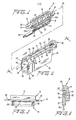
- Figure,l is a perspective view of an electrical connector suitable for receiving a protective hood constructed in accordance with the present invention and of a form shown in Figure 2.
- Figure 2 is a perspective view of a protective hood constructed in accordance with the present invention for use with an electrical connector of a type shown in Figure 1.
- Figure 3 is a side view of this electrical connector shown in Figure 1.
- Figure 4 is a planar cross-sectional view of the hood shown in Figure 2 taken along a plane defined by line 4 - 4 and looking in the direction of the arrows.
- Figure 5 is a bottom view of the connector shown in Figure 1.
- Figure 6 is a planar cross-sectional view of a modified portion of one hood sidewall taken along a plane defined by line 5-6 of Figure 2 and illustrating the cooperation between a ramped surface of the rail engaging recess therein and a hood support rail of a connector.
- Turning now to Figure 1, a one-piece all plastic
electrical connector 10 is shown, having amating end portion 12 and a conductortermination end portion 14 formed integral with a base orsupport portion 16. At each longitudinal extremity of thebase portion 16, amounting flange portion 18 is provided withholes 20 for mounting theconnector 12 to a printed circuit board, metal chassis, rack panel or the like through the use of suitable fasteners. - Typically, the conductor termination end portion of a connector such as 10 is provided with hood support means such as
rails 22. Each of the rails extends outwardly from a respectivemajor side surface 23 of the connectorconductor termination portion 14 from a position displaced from the lowermost surface of thebase 16 to form a longitudinally runningrecess 24 open at each of itsends connector 10. - The
mating portion 12 ofconnector 10 will, in accordance with custom, be considered the front portion of the connector while theconductor termination portion 14 will be considered the rear portion of the connector. - The conductor termination or
rear portion 14 of theconnector 10 is of generally rectangular configuration with two substantially transverseflat end surfaces 28 best seen by reference to Figures 1, 3, and 5. - Turning now to Figure 2, a
protective hood 30 constructed in accordance with the present invention is shown, and as will become more clearly apparent hereinafter, is adapted to engage thehood support rails 22 ofconnector 10 and slide across the longitudinally extending surfaces of the connectorconductor termination portion 14. The hood then acts as a protective cover for theconductor termination portion 14 of the connector to protect exposed surfaces of the conductors 26' and the respective contacts to which they are connected from inadvertent shortcircuiting or grounding after the protective hood has been assembled. - In accordance with the present invention, at the termination of the hood assembly process, the hood positively engages the termination and portion end of the connector with an audible and distinct signal or "snap".
- More specifically, and still referring to Figure 2,
hood 30 is made of a flexible plastic material such as ABS Cycolac KJB and comprises two sidewall portions or members 32 (see also Figure 4) and an end wall portion ormember 34 extending from the two lateral extremities and one end extremity, respectively, of a bottom wall portion ofmember 36.Cavity 38 which is thus formed is closed at one longitudinal extremity by theend wall portion 34. The hood is dimensioned such that the lateral distance between the inner surfaces ofsidewall portion 32 allows theconductor termination portion 14 to be freely received within thecavity 38. - As shown in Figure 2, the top or uppermost extremity of each
sidewall 32 is provided with a longitudinally extendinglip member 40. Thelip members 40 extend transversely inwardly toward one another to partially close thecavity 38 at its top. Preferably, the lateral distance 41' between theopposing surfaces 41 of the twolip members 40 which define the longitudinally extending rectangularly shaped opening 4l'' is such that the lips snugly embrace the side surfaces of the connector. Arecess 42 indicated betweenreference numerals hood 30 and generally parallel to thebottom portion 36. Each of the recesses are dimensioned to receive the hood support rails of theconnector 10 upon assembly of thehood 30 to theconnector 10. - As shown in Figures 2 and 4, the extremities of each
recess 43 immediately adjacent to the open end ofcavity 38 is, in turn, open to receive the connector hood support rails. The other ends of these recesses are closed as shown at 46. - In accordance with the present invention and as best seen in Figure 2, the left-hand extremities of the
lip members 40 are provided with aramp 52 which, in the embodiment shown, form part of rampedlatch hook 48. Eachhook 48 has alocking surface 50. Additionally, in a preferred embodiment of the present invention, the longitudinal extremities of thehood support rails 22 ofconnector 10 are chamfered as shown at 54- (see Figure 5) to ease hood assembly on the connector; In.further accordance with the present invention, the distance between the latching orlocking surfaces 50 and the closedextremities 46 of therecesses 43 are dimensioned such that when thehood 30 is fully assembled onconnector 10,locking surfaces 50 engage theend surfaces 28 of theconductor termination portion 14 of the connector. - As hereinbefore noted, in accordance with the present invention, the lateral distance between the two
lateral surfaces 41 of the twolip members 40 are such that these surfaces snugly engage the major side surfaces 56 (see Figure 5) of the connector conductortermination end portion 14 when the hood is fully assembled thereon. - The
hood 30 is therefore assembled on theconnector 10 by engaging therecesses 43 of the hood with thehood support rails 22 and by longitudinally sliding the hood along the rails in the direction of arrow 60 (Figure 1). - Upon the initial engagement of the
recesses 43 and rails 22, the ramp surfaces 52 of thehooks 48 displace each sidewall in'a direction away from the major side surfaces 23 of the connectortermination end portion 14 against forces resulting from the elastic properties of the sidewall material. Upon the hood reaching its fully assembled position on the connector, thehooks 48 are forced inwardly and over the end surfaces 28 of the connector by the elastic forces produced by the hood wall material. The relativelyplanar surfaces 50 extending from the peak of the ramp substantially perpendicularly to theedge surface 41 of thelip 40 then lock or latch the hood to the connector so as to inhibit relative movement therebetween. - Thus, in accordance with the invention, the ramp means act to disenable the locking or latching means 50 until the hood is fully assembled on the connector. Although the ramp member and locking means are shown as being formed as a
hook 48, it will be appreciated that these two elements may be formed at displaced positions on the hood. Moreover, it is contemplated that the locking means may act upon other surfaces of the connector body which are complementary to the locking surfaces defined by the hood walls. - To remove the hood from the connector, one or both of the hood sidewall member(s) 32 may be manually flexed away from the connector body by means of the fingers on a human hand sufficiently to disengage planar surface(s) 50 of the hook(s) 48 from the end surface(s) 28 of the connector. This will thereby disenable the locking means whereupon the hood may be slid along the
rails 22 and removed from theconnector 10. - In a preferred form of the present invention, the manual flexing of one or both of the
sidewall members 32, incident to hood removal as aforesaid, may be accomplished by simply pushingbottom wall member 36 adjacent the open end of the hood toward theconnector 10. This is made possible by providinq the lowermost surface of eachrail receiving recess 42 with a rampedsection 60 as shown in Figure 6. The ramped section should be placed in close juxtaposition to thehooks 48. Thus, when a force "F" is placed on the bottom wall of the hood in the direction ofarrow 62 relative to theconnector 10, the surface of the rampedsection 60 will engage the lower edge of therail 22. This will then cam thesidewall 32 in the direction ofarrow 64 away from theconnector termination portion 14 as the hood moves toward the connector in the direction ofarrow 62. The dimensions or distance between the upper outer surface 40' ofhood lip member 40 and theadjacent surface 64 ofmember 14 as well as the transverse dimension of the active surface of rampedsection 60 is such that the extent of hood wall flexing will be such to disengage thehooks 48 from the connector body so that the hood may be removed from the connector as described hereinbefore. - Alternatively, the ramped
section 60 may be eliminated and the outer lower edge ofrail 22 chamfered to provide a ramp surface will cooperate with the lower edge ofrecess 42 to effectuate the aforesaid flexing of the sidewall when the bottom of the hood is pushed. - It will be understood that the invention described hereinabove may be embodied in other specific forms without departing from the spirit or central characteristics thereof. The present examples and embodiments therefore are to be considered in all respects as illustrational and not restrictive and the invention is not to be limited to the details given herein, but only in accordance with the appended claims when read in the light of the foregoing specification.
Claims (12)
- Claim 1 - A protective hood for the termination end portion of an electrical connector, said hood comprising:a first and second sidewall member formed of stiff material with elastic properties joined to an end wall and a bottom wall member to form an open ended cavity with a substantially open top, the cavity being dimensioned to snugly receive and contain the termination end portion of the connector when said end portion is moved in a longitudinal direction relative to the hood into the open end of said cavity,locking means carried 'at least in part by at least one sidewall member for automatically locking the hood to the connector in response to the elastic properties of said sidewall member when the hood reaches its fully assembled position on the connector,and camming means carried at least in part by said hood sidewall member adjacent the open end of said cavity for interacting with the termination end portion of the connector so as to displace said sidewall member in a direction away from the connector during the principal portion of the longitudinal movement of the hood relative to the connector during its assembly thereon to disenable said locking means until the hood reaches its fully assembled position, whereupon the camming means allows the hood wall member to abruptly return to its predisplacement condition with an audible "snap" and lock the. hood to the connector.
- Claim 2 - A protective hood according to claim 1 wherein the uppermost edge of said sidewall is provided with a lip extending transversely toward the said other sidewall and said camming means includes a ramp positioned near the longitudinal and transverse extremities of said lip adjacent the open end of said cavity for displacing said lip in a direction away from said connector upon its entry into said food cavity.
- Claim 3 - A protective hood according to claim 2 wherein said ramp terminates at the extremity thereof most remote from the open end of said cavity, in a surface which is substantially perpendicular to the longitudinal edge of said lip.
- Claim 4 - A protective hood according to claim 1 wherein said locking means carried by said sidewall member comprises means defining a laterally extending surface which is complementary to and positioned relative to the open end of said cavity so as to be engageable with a surface defined by a portion of said connector when said hood is fully assembled thereon to inhibit longitudinal motion of said hood relative to the connector according to claim 3.
- Claim 5 - A protective hood according to claim 3 wherein said locking means comprises said relatively planar surface of said ramp termination and wherein said ramp is positioned relative to the open end of said cavity so as to engage one longitudinal extremity of the termination end portion of a connector when said hood is fully assembled on the connector.
- Claim 6 - In combination, an electrical connector having a substantially rectangular termination end portion and a protective hood covering said end portion, said connector having a longitudinally extending hood support rail on at least one major side surface of said termination end portion,
- said hood being formed of relatively thin flexible material having elastic properties and comprising at least two sidewalls extending from a bottom wall with means formed on the inner side of at least one sidewall adjacent the uppermost extremity thereof for engaging said hood support rail so as to allow said hood to be slidably attached to and removed from said connector,
- ramp means affixed to the inner surface of said at least one sidewall adjacent said rail engaging means for engaging side surface of said connector termination end portion during sliding assembly of said hood on said connector to move said sidewall in a direction away from said side surface against elastic forces produced by said sidewall material and disengaging said surface upon the full assembly of said hood on said connector,
- and locking means affixed to the inner surface of said one sidewall in relatively close juxtaposition to said ramp means for engaging said termination end portion only when said hood reaches its fully assembled position on said connector and said ramp disengages said major side surface.
- Claim 7 - A protective hood according to claim 6 wherein said termination end portion is chamfered at each longitudinal extremity thereof to form ramp surfaces for sliding interengagement with said hood ramp means during assembly of said hood upon said connector.
- Claim 8 - The combination according to claim 6 wherein said hood support rail has upper and lower longitudinally extending surfaces and wherein said hood support rail engaging means comprises a longitudinally extending recess having an upper and a lower surface for engaging a hood support rail and wherein cam means are provided acting between at least a portion of said lower recess surface and at least a portion of said lower surface of said rail such that manual pressure upon the bottom wall of said hood will cause said sidewall to flex and disenable said locking means whereby said hood after being fully assembled upon said connector may be removed therefrom.
- Claim 9 - In an electrical connector having a pro- tective hood releasably mounted thereon the combination of: locking means carried by said hood and said connector for locking said hood to said connector when said hood is fully assembled thereon and means carried by said hood and said connector responsive to the application of pressure therebetween for disenabling said locking means such that said hood may be removed from said connector.
Priority Applications (1)
| Application Number | Priority Date | Filing Date | Title |
|---|---|---|---|
| AT83108563T ATE32964T1 (en) | 1982-09-17 | 1983-08-31 | ELECTRICAL CONNECTORS WITH A PROTECTIVE HOOD. |
Applications Claiming Priority (2)
| Application Number | Priority Date | Filing Date | Title |
|---|---|---|---|
| US06/419,387 US4483580A (en) | 1982-09-17 | 1982-09-17 | Electrical connectors with protective hood |
| US419387 | 1999-10-15 |
Publications (2)
| Publication Number | Publication Date |
|---|---|
| EP0103787A1 true EP0103787A1 (en) | 1984-03-28 |
| EP0103787B1 EP0103787B1 (en) | 1988-03-09 |
Family
ID=23662045
Family Applications (1)
| Application Number | Title | Priority Date | Filing Date |
|---|---|---|---|
| EP83108563A Expired EP0103787B1 (en) | 1982-09-17 | 1983-08-31 | Electrical connectors with protective hood |
Country Status (8)
| Country | Link |
|---|---|
| US (1) | US4483580A (en) |
| EP (1) | EP0103787B1 (en) |
| AT (1) | ATE32964T1 (en) |
| AU (1) | AU1907483A (en) |
| CA (1) | CA1199087A (en) |
| DE (1) | DE3375966D1 (en) |
| IN (1) | IN160967B (en) |
| NZ (1) | NZ205624A (en) |
Cited By (3)
| Publication number | Priority date | Publication date | Assignee | Title |
|---|---|---|---|---|
| DE8715118U1 (en) * | 1987-11-13 | 1989-03-16 | Grote & Hartmann Gmbh & Co Kg, 5600 Wuppertal, De | |
| EP0655799A1 (en) * | 1993-11-26 | 1995-05-31 | Molex Incorporated | Hooded electrical connector with terminal position assurance means |
| US7323187B1 (en) | 1999-08-27 | 2008-01-29 | Schuer Joerg Peter | Impregnation method |
Families Citing this family (10)
| Publication number | Priority date | Publication date | Assignee | Title |
|---|---|---|---|---|
| JPH0517821Y2 (en) * | 1988-07-27 | 1993-05-12 | ||
| GB9026390D0 (en) * | 1990-12-05 | 1991-01-23 | Mcdonald George W | Folded sheet means |
| DE4330626C2 (en) * | 1993-09-09 | 1997-11-27 | Siemens Ag | Electrical connector |
| EP0776068B1 (en) * | 1995-11-21 | 2001-06-06 | The Whitaker Corporation | Electrical connector assembly |
| JPH11250973A (en) * | 1998-03-04 | 1999-09-17 | Yazaki Corp | Locking structure of connector |
| JP4520315B2 (en) * | 2005-01-21 | 2010-08-04 | タイコエレクトロニクスジャパン合同会社 | Wire cover for connector |
| CN104425953A (en) * | 2013-08-29 | 2015-03-18 | 鸿富锦精密工业(深圳)有限公司 | Connector assembly |
| TWI668922B (en) * | 2013-12-18 | 2019-08-11 | 新加坡商Fci連接器新加坡有限公司 | Electrical cable connector and connector assembly thereof |
| US9293858B2 (en) * | 2014-05-26 | 2016-03-22 | Bren-Tronics, Inc. | Screw down connector |
| JP7268083B2 (en) * | 2021-05-13 | 2023-05-02 | 矢崎総業株式会社 | protector and wire harness |
Citations (3)
| Publication number | Priority date | Publication date | Assignee | Title |
|---|---|---|---|---|
| US3926497A (en) * | 1974-03-12 | 1975-12-16 | Du Pont | Connector shroud and assembly |
| US3936129A (en) * | 1974-09-16 | 1976-02-03 | Western Electric Company, Inc. | Molded plastic hood assembly for a cable connector plug |
| US4130330A (en) * | 1977-10-06 | 1978-12-19 | Amp Incorporated | Electrical connector strain relief and cover retention system |
Family Cites Families (3)
| Publication number | Priority date | Publication date | Assignee | Title |
|---|---|---|---|---|
| US4203643A (en) * | 1978-07-24 | 1980-05-20 | Bunker Ramo Corporation | Electrical ribbon connector and hood |
| US4211463A (en) * | 1979-02-12 | 1980-07-08 | Amp Incorporated | Metal strain relief clamp |
| US4432592A (en) * | 1979-02-21 | 1984-02-21 | Allied Corporation | Electrical connector assembly |
-
1982
- 1982-09-17 US US06/419,387 patent/US4483580A/en not_active Expired - Fee Related
-
1983
- 1983-08-31 EP EP83108563A patent/EP0103787B1/en not_active Expired
- 1983-08-31 DE DE8383108563T patent/DE3375966D1/en not_active Expired
- 1983-08-31 AT AT83108563T patent/ATE32964T1/en not_active IP Right Cessation
- 1983-09-13 AU AU19074/83A patent/AU1907483A/en not_active Abandoned
- 1983-09-16 CA CA000436869A patent/CA1199087A/en not_active Expired
- 1983-09-16 IN IN1133/CAL/83A patent/IN160967B/en unknown
- 1983-09-16 NZ NZ205624A patent/NZ205624A/en unknown
Patent Citations (3)
| Publication number | Priority date | Publication date | Assignee | Title |
|---|---|---|---|---|
| US3926497A (en) * | 1974-03-12 | 1975-12-16 | Du Pont | Connector shroud and assembly |
| US3936129A (en) * | 1974-09-16 | 1976-02-03 | Western Electric Company, Inc. | Molded plastic hood assembly for a cable connector plug |
| US4130330A (en) * | 1977-10-06 | 1978-12-19 | Amp Incorporated | Electrical connector strain relief and cover retention system |
Cited By (3)
| Publication number | Priority date | Publication date | Assignee | Title |
|---|---|---|---|---|
| DE8715118U1 (en) * | 1987-11-13 | 1989-03-16 | Grote & Hartmann Gmbh & Co Kg, 5600 Wuppertal, De | |
| EP0655799A1 (en) * | 1993-11-26 | 1995-05-31 | Molex Incorporated | Hooded electrical connector with terminal position assurance means |
| US7323187B1 (en) | 1999-08-27 | 2008-01-29 | Schuer Joerg Peter | Impregnation method |
Also Published As
| Publication number | Publication date |
|---|---|
| CA1199087A (en) | 1986-01-07 |
| IN160967B (en) | 1987-08-22 |
| ATE32964T1 (en) | 1988-03-15 |
| EP0103787B1 (en) | 1988-03-09 |
| US4483580A (en) | 1984-11-20 |
| AU1907483A (en) | 1984-03-22 |
| DE3375966D1 (en) | 1988-04-14 |
| NZ205624A (en) | 1987-02-20 |
Similar Documents
| Publication | Publication Date | Title |
|---|---|---|
| EP0103787A1 (en) | Electrical connectors with protective hood | |
| US5754406A (en) | Printed circuit board card guide having isolation arms and means for securing PCB | |
| US5445534A (en) | Double lock male/female type connector | |
| EP0734599B1 (en) | Connector assembly for ic card | |
| US4477137A (en) | Zero insertion force connector for flat cable | |
| US5613870A (en) | Positive latching connector with delatching mechanism | |
| KR0139588B1 (en) | Shunted connector assembly and shunt assembly for it | |
| US5525072A (en) | Electrical connector assembly for interconnecting a flat cable to a circuit board | |
| EP0963014B1 (en) | Electrical connector assembly for connecting flat flexible circuitry to discrete electrical terminals | |
| US6398577B1 (en) | Latching/unlatching system for electrical connectors | |
| US5582520A (en) | Electrostrip receptacle | |
| WO1986003345A1 (en) | Electrical connector | |
| US5980313A (en) | System for mounting an electrical connector on a panel | |
| US7077703B2 (en) | Plug connector | |
| US4113337A (en) | Connector constructions and mounting means and hoods therefor | |
| US5595498A (en) | Connector for electrical trunking | |
| US4257028A (en) | Remote socket for DIP components | |
| EP0619624B1 (en) | Electrical connector for flat cable | |
| US4203643A (en) | Electrical ribbon connector and hood | |
| US4447102A (en) | Electrical connector assemblies | |
| US6155851A (en) | Connector locking structure | |
| US3982809A (en) | Cord adapter | |
| US4172627A (en) | Multiple electrical connecting device | |
| JPH0234772Y2 (en) | ||
| US4241972A (en) | Panel mount for electrical connector |
Legal Events
| Date | Code | Title | Description |
|---|---|---|---|
| PUAI | Public reference made under article 153(3) epc to a published international application that has entered the european phase |
Free format text: ORIGINAL CODE: 0009012 |
|
| AK | Designated contracting states |
Designated state(s): AT BE CH DE FR GB IT LI NL SE |
|
| 17P | Request for examination filed |
Effective date: 19840926 |
|
| ITF | It: translation for a ep patent filed |
Owner name: INTERPATENT ST.TECN. BREV. |
|
| GRAA | (expected) grant |
Free format text: ORIGINAL CODE: 0009210 |
|
| AK | Designated contracting states |
Kind code of ref document: B1 Designated state(s): AT BE CH DE FR GB IT LI NL SE |
|
| REF | Corresponds to: |
Ref document number: 32964 Country of ref document: AT Date of ref document: 19880315 Kind code of ref document: T |
|
| REF | Corresponds to: |
Ref document number: 3375966 Country of ref document: DE Date of ref document: 19880414 |
|
| ET | Fr: translation filed | ||
| PG25 | Lapsed in a contracting state [announced via postgrant information from national office to epo] |
Ref country code: LI Effective date: 19880831 Ref country code: GB Free format text: LAPSE BECAUSE OF NON-PAYMENT OF DUE FEES Effective date: 19880831 Ref country code: CH Effective date: 19880831 Ref country code: BE Effective date: 19880831 Ref country code: AT Effective date: 19880831 |
|
| PG25 | Lapsed in a contracting state [announced via postgrant information from national office to epo] |
Ref country code: SE Effective date: 19880901 |
|
| PLBE | No opposition filed within time limit |
Free format text: ORIGINAL CODE: 0009261 |
|
| STAA | Information on the status of an ep patent application or granted ep patent |
Free format text: STATUS: NO OPPOSITION FILED WITHIN TIME LIMIT |
|
| BERE | Be: lapsed |
Owner name: ALLIED CORP. Effective date: 19880831 |
|
| PG25 | Lapsed in a contracting state [announced via postgrant information from national office to epo] |
Ref country code: NL Effective date: 19890301 |
|
| 26N | No opposition filed | ||
| NLV4 | Nl: lapsed or anulled due to non-payment of the annual fee | ||
| PG25 | Lapsed in a contracting state [announced via postgrant information from national office to epo] |
Ref country code: FR Free format text: LAPSE BECAUSE OF NON-PAYMENT OF DUE FEES Effective date: 19890428 |
|
| REG | Reference to a national code |
Ref country code: CH Ref legal event code: PL |
|
| PG25 | Lapsed in a contracting state [announced via postgrant information from national office to epo] |
Ref country code: DE Effective date: 19890503 |
|
| GBPC | Gb: european patent ceased through non-payment of renewal fee | ||
| REG | Reference to a national code |
Ref country code: FR Ref legal event code: ST |
|
| EUG | Se: european patent has lapsed |
Ref document number: 83108563.4 Effective date: 19890712 |