EP0963014B1 - Electrical connector assembly for connecting flat flexible circuitry to discrete electrical terminals - Google Patents
Electrical connector assembly for connecting flat flexible circuitry to discrete electrical terminals Download PDFInfo
- Publication number
- EP0963014B1 EP0963014B1 EP99110333A EP99110333A EP0963014B1 EP 0963014 B1 EP0963014 B1 EP 0963014B1 EP 99110333 A EP99110333 A EP 99110333A EP 99110333 A EP99110333 A EP 99110333A EP 0963014 B1 EP0963014 B1 EP 0963014B1
- Authority
- EP
- European Patent Office
- Prior art keywords
- terminals
- body portion
- flexible circuit
- female connector
- connector assembly
- Prior art date
- Legal status (The legal status is an assumption and is not a legal conclusion. Google has not performed a legal analysis and makes no representation as to the accuracy of the status listed.)
- Expired - Lifetime
Links
Images


Classifications
-
- H—ELECTRICITY
- H01—ELECTRIC ELEMENTS
- H01R—ELECTRICALLY-CONDUCTIVE CONNECTIONS; STRUCTURAL ASSOCIATIONS OF A PLURALITY OF MUTUALLY-INSULATED ELECTRICAL CONNECTING ELEMENTS; COUPLING DEVICES; CURRENT COLLECTORS
- H01R11/00—Individual connecting elements providing two or more spaced connecting locations for conductive members which are, or may be, thereby interconnected, e.g. end pieces for wires or cables supported by the wire or cable and having means for facilitating electrical connection to some other wire, terminal, or conductive member, blocks of binding posts
- H01R11/01—Individual connecting elements providing two or more spaced connecting locations for conductive members which are, or may be, thereby interconnected, e.g. end pieces for wires or cables supported by the wire or cable and having means for facilitating electrical connection to some other wire, terminal, or conductive member, blocks of binding posts characterised by the form or arrangement of the conductive interconnection between the connecting locations
-
- H—ELECTRICITY
- H01—ELECTRIC ELEMENTS
- H01R—ELECTRICALLY-CONDUCTIVE CONNECTIONS; STRUCTURAL ASSOCIATIONS OF A PLURALITY OF MUTUALLY-INSULATED ELECTRICAL CONNECTING ELEMENTS; COUPLING DEVICES; CURRENT COLLECTORS
- H01R12/00—Structural associations of a plurality of mutually-insulated electrical connecting elements, specially adapted for printed circuits, e.g. printed circuit boards [PCB], flat or ribbon cables, or like generally planar structures, e.g. terminal strips, terminal blocks; Coupling devices specially adapted for printed circuits, flat or ribbon cables, or like generally planar structures; Terminals specially adapted for contact with, or insertion into, printed circuits, flat or ribbon cables, or like generally planar structures
- H01R12/70—Coupling devices
- H01R12/77—Coupling devices for flexible printed circuits, flat or ribbon cables or like structures
- H01R12/81—Coupling devices for flexible printed circuits, flat or ribbon cables or like structures connecting to another cable except for flat or ribbon cable
-
- H—ELECTRICITY
- H01—ELECTRIC ELEMENTS
- H01R—ELECTRICALLY-CONDUCTIVE CONNECTIONS; STRUCTURAL ASSOCIATIONS OF A PLURALITY OF MUTUALLY-INSULATED ELECTRICAL CONNECTING ELEMENTS; COUPLING DEVICES; CURRENT COLLECTORS
- H01R12/00—Structural associations of a plurality of mutually-insulated electrical connecting elements, specially adapted for printed circuits, e.g. printed circuit boards [PCB], flat or ribbon cables, or like generally planar structures, e.g. terminal strips, terminal blocks; Coupling devices specially adapted for printed circuits, flat or ribbon cables, or like generally planar structures; Terminals specially adapted for contact with, or insertion into, printed circuits, flat or ribbon cables, or like generally planar structures
- H01R12/50—Fixed connections
- H01R12/59—Fixed connections for flexible printed circuits, flat or ribbon cables or like structures
- H01R12/592—Fixed connections for flexible printed circuits, flat or ribbon cables or like structures connections to contact elements
Definitions
- This invention relates to an electrical connector assembly for electrically interconnecting a plurality of discrete electrical wires to conductors of a flat flexible circuit.
- a flat flexible circuit conventionally includes an elongated flat flexible dielectric substrate having laterally spaced strips of conductors on one or both sides thereof.
- the conductors may be covered with a thin, flexible protective layer on one or both sides of the circuit. If protective layers are used, cutouts are formed therein to expose the underlying conductors at desired contact locations where the conductors are to engage the conductors of a complementary mating connecting device which may be a second flat flexible circuit, a printed circuit board or the terminals of a mating connector.
- a connector construction wherein a generally sheet-like cable is inserted into an opening in a connector housing, so that the conductors of the cable are respectively pressed against and connected to a plurality of resilient connection terminals received in the housing.
- the electrical connection is provided by press-contacting the cable with a spring piece of the terminal. Therefore, with this kind of connection the distal edge of the spring piece scratches along the conductors of the cable, such that the conductors can be damaged, in particular during the reverse movement when separating the connector parts.
- the spring piece can also damage the very sensitive insulating material of the cable and is, therefore, subject to improvements with respect to reliability.
- a connector assembly is known to electrically and mechanically connect a flexible circuit to a circuit board also of the multilayer type.
- this connector assembly is not constructed to connect a flexible circuit to discrete electrical wires apart from conductors which are soldered to through-holes in the circuit board and extend perpendicularly to the mating direction of the connector assembly.
- a molded circuit component known from EP-A-0 411 613 comprises a body having partition walls forming grooves, and flat terminals which register to the grooves and are embedded in the body. Each groove is adapted to receive a lead wire which can be soldered to a respective flat terminal. Releasably connecting a plurality of electrical wires to the conductors of a flat flexible circuit, as with a connector assembly, is not possible.
- An electrical connector for flexible flat cable is shown in EP-A 0 388 216 and comprises a female connector including a connector housing and terminals, and a male connector made up of a connector cover and the flat cable.
- the connector housing of the female connector is a one-part member of tunnel-like construction wherein mounting cavities are provided for accommodating the terminals that are formed as springs with folded back portions.
- the present invention is directed to satisfying that need and solving the problems associated therewith.
- the present invention is extremely simple, inexpensive and reliable.
- An object, therefore, of the invention is to provide a new and improved electrical connector assembly for interconnecting a plurality of discrete electrical wires to the conductors of a flat flexible circuit.
- the connector assembly includes a female connector having a dielectric housing defining a receptacle.
- a plurality of discrete conductive terminals are mounted on the housing and are adapted for termination to the electrical wires.
- the terminals have contact portions exposed in the receptacle for engaging the conductors of the flat flexible circuit.
- a male connector includes a body portion adapted for insertion into the receptacle of the housing of the female connector.
- the body portion is adapted for positioning the flat flexible circuit thereon, with the conductors of the circuit facing away from the body portion for engaging the contact portions of the conductive terminals when the body portion is inserted into the receptacle.
- the invention contemplates the use of a yieldable backing structure on the body portion of the male connector beneath the flexible circuit for resiliently biasing the conductors of the circuit against the terminals of the female connector. Therefore, the terminals can be maintained rigid on the body portion of the male connector.
- the yieldable backing structure is a molded-in-place component.
- the body portion may be molded of plastic material and the molded-in-place component may be of an elastomeric material.
- the body portion may be molded of relatively rigid plastic material, and the molded-in-place component may be of silicone rubber material.
- the dielectric housing of the female connector is a multi-part assembly including at least a base part mounting the terminals and a cover part for clamping the male connector and, thereby, the conductors of the flexible circuit against the terminals.
- complementary interengaging latch means are provided between the base part and the cover part to hold the parts in clamping condition.
- the latch means include at least one flexible arm on one of the parts engageable with a latch surface on the other part.
- the invention is embodied in an electrical connector assembly, generally designated 10, for interconnecting a plurality of discrete electrical wires 12 to the conductors of a flat flexible circuit 14.
- the connector assembly includes a female connector, generally designated 16, and a male connector, generally designated 18.
- female connector 16 includes a dielectric housing, generally designated 19, which is a two-part assembly including a base part 20 and a cover part 22. Each part is generally planar whereby the two-part housing clamps male connector 18 between the base part and cover part, as described hereinafter.
- Each housing part 20 and 22 is a one-piece structure unitarily molded of dielectric material such as plastic or the like.
- the dielectric housing of the female connector may be fabricated of a one-piece unitarily molded housing whereby the two pieces of the housing are integrally attached by a living hinge or other connecting region to facilitate fabrication and form or mold the part in a single molding process.
- Base part 20 of housing assembly 19 includes a plurality of channels 24 for receiving a plurality of discrete conductive terminals 26. Only four of the terminals are shown in Figure 1 , although more terminals are contemplated. The terminals may be of different configurations and sizes to accommodate various applications and various flat flexible circuits, as discussed further below. Rear ends of the terminals are electrically terminated to discrete electrical wires 12. Front ends of the terminals define contact portions 28 which rest on top of a front ledge 30 of housing part 20 which acts as an anvil for the contact portions. The terminals are held on top of the base part by press fits between L-shaped upstanding partitions 32.
- complementary interengaging latch means are provided between base part 20 and cover part 22 of the two-part housing 19 of female connector 16.
- a pair of flexible latch arms 34 project upwardly from each opposite side of base part 20.
- the distal ends of the flexible latch arms are provided with inwardly directed hook portions 34a.
- Cover part 22 includes a pair of outwardly directed flanges 36 at each opposite side thereof which define latch surfaces for engagement beneath hook portions 34a of flexible latch arms 34. Therefore, the two-parts of housing 19 of female connector 16 are relatively movable between open positions shown in Figure 1 and closed positions shown in Figure 2 , with latch arms 34 and latch surfaces 36 interengaging to hold the housing parts in their closed positions.
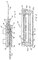
- FIG. 3 Another feature of the two-part female housing is shown in Fig. 3 , showing a cross-sectional view of the female housing in its closed position taken generally along lines 3-3 in Fig. 1 (but with the base part and the cover part in their assembled condition as in Fig. 2 ).
- Fig. 3 Another feature of the two-part female housing is shown in Fig. 3 , showing a cross-sectional view of the female housing in its closed position taken generally along lines 3-3 in Fig. 1 (but with the base part and the cover part in their assembled condition as in Fig. 2 ).
- upstanding partitions 32 will not fit within corresponding partition channels 37 and cover part 22 will not easily latch onto base part 20.
- upstanding partitions 32 and corresponding partition channels 37 function as a terminal position assurance feature for the female connector 16.
- male connector 18 of connector assembly 10 includes a body portion 38 about which flat flexible circuit 14 is wrapped.
- the male body portion is generally flat and elongated and includes a pair of cantilevered latch arms 40 at opposite sides thereof.
- the body portion, along with the latch arms, is unitarily molded of relatively rigid dielectric material such as plastic or the like.
- Cantilevered latch arms 40 are joined to body portion 38 at proximal ends 40a of the latch arms.
- the free ends of the latch arms are joined to the body portion by resilient webs 42.
- the latch arms have outwardly directed latch hooks 40b for snapping behind a portion of the female housing, such as front flexible latch arms 34 at opposite sides of base part 20, to hold male connector 18 within female connector 16.
- Male connector 18 for flexible circuit 14 is inserted into female connector 16 for discrete electrical wires 12 in the direction of arrow "A" ( Fig. 1 ).
- Figures 2 and 4 show the male connector fully inserted into the female connector.
- the two housing parts of the female connector define a receptacle 44 for receiving the male connector.
- body portion 38 of the male connector includes a plurality of locating pegs 46 ( Fig. 1 ) on the top thereof and a plurality of locating pegs 48 ( Fig. 5 ) on the bottom thereof.
- locating pegs 46 Fig. 1
- locating pegs 48 Fig. 5
- the circuit is located about body portion 38 by appropriate locating holes in the circuit which engage about the locating pegs on opposite sides of body portion 38 of the male connector.
- a yieldable backing structure in the form of an elongated strip 52 is provided on the underside of body portion 38 of male connector 18 for resiliently biasing the conductors of flexible circuit 14 against contact portions 28 of the terminals as described above in relation to Figure 4 .
- the yieldable backing structure or strip can be a molded-in-place component of elastomeric material such as silicone rubber or the like.
- body portion 38 of the male connector may be molded of relatively rigid plastic material, while yieldable backing strip 52 is molded of elastomeric material.
- the flexible circuit may be provided with any of a variety of widths or sizes of conductors which will be uniformly biased against corresponding contact portions in the female connector. Accordingly, the widths and the layout of the flexible circuit traces and the contact portions 28 must be coincidental, however such flexibility and variety is easily accommodated in the present design.
- the resilient backing strip lies behind flexible circuit 14 and biases the outwardly facing conductors of the circuit against contact portions 28 of terminals 26, while ledge portion 30 of base housing part 20 of the female connector acts as an anvil behind the contact portions of the terminals.
Landscapes
- Coupling Device And Connection With Printed Circuit (AREA)
- Multi-Conductor Connections (AREA)
- Details Of Connecting Devices For Male And Female Coupling (AREA)
Description
- This invention relates to an electrical connector assembly for electrically interconnecting a plurality of discrete electrical wires to conductors of a flat flexible circuit.
- A flat flexible circuit conventionally includes an elongated flat flexible dielectric substrate having laterally spaced strips of conductors on one or both sides thereof. The conductors may be covered with a thin, flexible protective layer on one or both sides of the circuit. If protective layers are used, cutouts are formed therein to expose the underlying conductors at desired contact locations where the conductors are to engage the conductors of a complementary mating connecting device which may be a second flat flexible circuit, a printed circuit board or the terminals of a mating connector.
- A wide variety of connectors have been designed over the years for terminating or interconnecting flat flexible circuits with complementary mating connecting devices.
- From
US-patent 5,397,247 a connector construction is provided, wherein a generally sheet-like cable is inserted into an opening in a connector housing, so that the conductors of the cable are respectively pressed against and connected to a plurality of resilient connection terminals received in the housing. However, the electrical connection is provided by press-contacting the cable with a spring piece of the terminal. Therefore, with this kind of connection the distal edge of the spring piece scratches along the conductors of the cable, such that the conductors can be damaged, in particular during the reverse movement when separating the connector parts. Furthermore, the spring piece can also damage the very sensitive insulating material of the cable and is, therefore, subject to improvements with respect to reliability. - From
US-patent 5,009,607 a connector assembly is known to electrically and mechanically connect a flexible circuit to a circuit board also of the multilayer type. However, this connector assembly is not constructed to connect a flexible circuit to discrete electrical wires apart from conductors which are soldered to through-holes in the circuit board and extend perpendicularly to the mating direction of the connector assembly. - A molded circuit component known from
EP-A-0 411 613 comprises a body having partition walls forming grooves, and flat terminals which register to the grooves and are embedded in the body. Each groove is adapted to receive a lead wire which can be soldered to a respective flat terminal. Releasably connecting a plurality of electrical wires to the conductors of a flat flexible circuit, as with a connector assembly, is not possible. - An electrical connector for flexible flat cable is shown in
EP-A 0 388 216 and comprises a female connector including a connector housing and terminals, and a male connector made up of a connector cover and the flat cable. The connector housing of the female connector is a one-part member of tunnel-like construction wherein mounting cavities are provided for accommodating the terminals that are formed as springs with folded back portions. - However, there has not been a reliable and cost effective system for electrically connecting a plurality of discrete electrical wires to flat flexible circuitry. Part of the problem resides in the fact that the terminals must somehow be biased against the flat circuitry. The present invention is directed to satisfying that need and solving the problems associated therewith. The present invention is extremely simple, inexpensive and reliable.
- An object, therefore, of the invention is to provide a new and improved electrical connector assembly for interconnecting a plurality of discrete electrical wires to the conductors of a flat flexible circuit.
- In the exemplary embodiment of the invention, the connector assembly includes a female connector having a dielectric housing defining a receptacle. A plurality of discrete conductive terminals are mounted on the housing and are adapted for termination to the electrical wires. The terminals have contact portions exposed in the receptacle for engaging the conductors of the flat flexible circuit.
- A male connector includes a body portion adapted for insertion into the receptacle of the housing of the female connector. The body portion is adapted for positioning the flat flexible circuit thereon, with the conductors of the circuit facing away from the body portion for engaging the contact portions of the conductive terminals when the body portion is inserted into the receptacle.
- The invention contemplates the use of a yieldable backing structure on the body portion of the male connector beneath the flexible circuit for resiliently biasing the conductors of the circuit against the terminals of the female connector. Therefore, the terminals can be maintained rigid on the body portion of the male connector. Preferably, the yieldable backing structure is a molded-in-place component. The body portion may be molded of plastic material and the molded-in-place component may be of an elastomeric material. For instance, the body portion may be molded of relatively rigid plastic material, and the molded-in-place component may be of silicone rubber material.
- As disclosed herein, the dielectric housing of the female connector is a multi-part assembly including at least a base part mounting the terminals and a cover part for clamping the male connector and, thereby, the conductors of the flexible circuit against the terminals. Preferably, complementary interengaging latch means are provided between the base part and the cover part to hold the parts in clamping condition. As disclosed herein, the latch means include at least one flexible arm on one of the parts engageable with a latch surface on the other part.
- Other objects, features and advantages of the invention will be apparent from the following detailed description taken in connection with the accompanying drawings.
- The features of this invention which are believed to be novel are set forth with particularity in the appended claims. The invention, together with its objects and the advantages thereof, may be best understood by reference to the following description taken in conjunction with the accompanying drawings, in which like reference numerals identify like elements in the figures and in which:
-
FIGURE 1 is an exploded perspective view of the electrical connector assembly for interconnecting a plurality of discrete electrical wires to the conductors of a flat flexible circuit; -
FIGURE 2 is a perspective view of the connector assembly in fully closed and mated condition; -
FIGURE 3 is a vertical section taken generally along line 3-3 ofFigure 1 , but with the base part and the cover part of the female connector in their closed position; -
FIGURE 4 is a vertical section taken generally along line 4-4 ofFigure 2 ; and -
FIGURE 5 is a perspective view of the underside of the male connector as viewed inFigure 1 . - Referring to the drawings in greater detail, and first to
Figure 1 , the invention is embodied in an electrical connector assembly, generally designated 10, for interconnecting a plurality of discreteelectrical wires 12 to the conductors of a flatflexible circuit 14. The connector assembly includes a female connector, generally designated 16, and a male connector, generally designated 18. - More particularly,
female connector 16 includes a dielectric housing, generally designated 19, which is a two-part assembly including abase part 20 and acover part 22. Each part is generally planar whereby the two-part housing clampsmale connector 18 between the base part and cover part, as described hereinafter. Eachhousing part -
Base part 20 ofhousing assembly 19 includes a plurality ofchannels 24 for receiving a plurality of discreteconductive terminals 26. Only four of the terminals are shown inFigure 1 , although more terminals are contemplated. The terminals may be of different configurations and sizes to accommodate various applications and various flat flexible circuits, as discussed further below. Rear ends of the terminals are electrically terminated to discreteelectrical wires 12. Front ends of the terminals definecontact portions 28 which rest on top of afront ledge 30 ofhousing part 20 which acts as an anvil for the contact portions. The terminals are held on top of the base part by press fits between L-shapedupstanding partitions 32. - Generally, complementary interengaging latch means are provided between
base part 20 andcover part 22 of the two-part housing 19 offemale connector 16. Specifically, a pair offlexible latch arms 34 project upwardly from each opposite side ofbase part 20. The distal ends of the flexible latch arms are provided with inwardly directedhook portions 34a.Cover part 22 includes a pair of outwardly directedflanges 36 at each opposite side thereof which define latch surfaces for engagement beneathhook portions 34a of flexiblelatch arms 34. Therefore, the two-parts ofhousing 19 offemale connector 16 are relatively movable between open positions shown inFigure 1 and closed positions shown inFigure 2 , withlatch arms 34 andlatch surfaces 36 interengaging to hold the housing parts in their closed positions. The closed positions of the housing parts define a clamping condition offemale connector 16 aboutmale connector 18, as will be seen hereinafter. Another feature of the two-part female housing is shown inFig. 3 , showing a cross-sectional view of the female housing in its closed position taken generally along lines 3-3 inFig. 1 (but with the base part and the cover part in their assembled condition as inFig. 2 ). As can be seen in this view, ifterminal 26 is not properly positioned within itsrespective channel 24,upstanding partitions 32 will not fit withincorresponding partition channels 37 and coverpart 22 will not easily latch ontobase part 20. In this way,upstanding partitions 32 andcorresponding partition channels 37 function as a terminal position assurance feature for thefemale connector 16. - Looking again to
Fig. 1 ,male connector 18 of connector assembly 10 includes abody portion 38 about which flatflexible circuit 14 is wrapped. The male body portion is generally flat and elongated and includes a pair ofcantilevered latch arms 40 at opposite sides thereof. The body portion, along with the latch arms, is unitarily molded of relatively rigid dielectric material such as plastic or the like. Cantilevered latcharms 40 are joined tobody portion 38 at proximal ends 40a of the latch arms. The free ends of the latch arms are joined to the body portion byresilient webs 42. The latch arms have outwardly directed latch hooks 40b for snapping behind a portion of the female housing, such as frontflexible latch arms 34 at opposite sides ofbase part 20, to holdmale connector 18 withinfemale connector 16. -
Male connector 18 forflexible circuit 14 is inserted intofemale connector 16 for discreteelectrical wires 12 in the direction of arrow "A" (Fig. 1 ).Figures 2 and4 show the male connector fully inserted into the female connector. The two housing parts of the female connector define areceptacle 44 for receiving the male connector. When the connectors are fully mated, the conductors on abottom side 14a (Fig. 4 ) of flatflexible circuit 14 are biased againstcontact portions 28 ofterminals 26 which are terminated to discreteelectrical wires 12. - Referring to
Figure 5 in conjunction withFigure 1 ,body portion 38 of the male connector includes a plurality of locating pegs 46 (Fig. 1 ) on the top thereof and a plurality of locating pegs 48 (Fig. 5 ) on the bottom thereof. Whenflexible circuit 14 is wrapped about a leading edge 50 (Fig. 5 ), the circuit is located aboutbody portion 38 by appropriate locating holes in the circuit which engage about the locating pegs on opposite sides ofbody portion 38 of the male connector. - Referring to
Figure 5 in conjunction withFigure 4 , a yieldable backing structure in the form of anelongated strip 52 is provided on the underside ofbody portion 38 ofmale connector 18 for resiliently biasing the conductors offlexible circuit 14 againstcontact portions 28 of the terminals as described above in relation toFigure 4 . The yieldable backing structure or strip can be a molded-in-place component of elastomeric material such as silicone rubber or the like. In other words,body portion 38 of the male connector may be molded of relatively rigid plastic material, whileyieldable backing strip 52 is molded of elastomeric material. Since the elastomeric material extends continuously along the width of the male connector, the flexible circuit may be provided with any of a variety of widths or sizes of conductors which will be uniformly biased against corresponding contact portions in the female connector. Accordingly, the widths and the layout of the flexible circuit traces and thecontact portions 28 must be coincidental, however such flexibility and variety is easily accommodated in the present design. With this structural combination, as clearly seen inFigure 4 , the resilient backing strip lies behindflexible circuit 14 and biases the outwardly facing conductors of the circuit againstcontact portions 28 ofterminals 26, whileledge portion 30 ofbase housing part 20 of the female connector acts as an anvil behind the contact portions of the terminals.
Claims (11)
- An electrical connector assembly (10) for interconnecting a plurality of discrete electrical wires (12) to the conductors of a flat flexible circuit (14), comprising:a female connector (16) includinga dielectric housing (19) defining a receptacle (44), anda plurality of discrete conductive terminals (26) mounted on the housing with the terminals (26) having contact portions (28) exposed in said receptacle (44) for engaging the conductors of the flat flexible circuit (14); anda male connector (18) includingcharacterized in thata body portion (38) for insertion into the receptacle (44) of the housing (19) of the female connector (16),the body portion (38) being adapted for positioning the flat flexible circuit (14) thereon with the conductors of the circuit facing away from the body portion for engaging said conductive terminals (26) when the body portion (38) is inserted into the receptacle (44), anda yieldable backing structure (52) on the body portion (38) acting on the flexible circuit (14) for resiliently biasing the conductors of the flexible circuit (14) against the terminals (26) of the female connector (16),
each discrete terminal (26) of the female connector (16) comprises a contact portion (28) and forms a substantially straight connection line from the respective wire (12) to the respective conductor of the flat flexible circuit (14),
the dielectric housing (19) of the female connector (16) comprises a generally planar base part (20) and a generally planar cover part (22),
the base part (20) opposite to said cover part (22) has a side that includes a plurality of channels (24) and a ledge (30) for rigidly backing the contact portions (28) of the terminals (26),
said channels (24) extend on said base part side and mount said discrete terminals (26) and the ends of said wires (12) with the terminals (26) being held on said base part side and adapted for termination to said electrical wires (12),
and in that said cover part (22) and said base part (20) including said ledge (30) define said receptacle (44),
wherein the male connector (18) and, thereby, the conductors of the flexible circuit (14) are clamped against the terminals (26) of the female connector (16). - The electrical connector assembly of claim 1
wherein said body portion (38) includes integral locating pegs (46, 48) adapted to engage corresponding locating holes in the flat flexible circuit (14) for locating the flat flexible circuit (14) relative to the body portion (38). - The electrical connector assembly of claim 1 or 2
wherein said yieldable backing structure (52) of the male connector (18)is a molded-in-place component. - The electrical connector assembly of claim 3 wherein said body portion (38) is molded of plastic material and said molded-in-place component (52) is of an elastomeric material.
- The electrical connector assembly of claim 4 wherein said body portion (38) is molded of relatively rigid plastic material.
- The electrical connector assembly of claim 4 or 5
wherein said molded-in-place component (52) is of silicone rubber material. - The electrical connector assembly of any of claims 1-6
wherein said dielectric housing (19) of the female connector (16) is a multi-part assembly including at least said base part (20) mounting the terminals (26) and said cover part (22) and including complementary interengaging latch means (34, 36) between the base part (20) and the cover part (22) of the female connector (16) to hold the parts in clamping condition. - The electrical connector assembly of claim 7 wherein said latch means include at least one flexible latch arm (34) on one of the parts (20) engageable with a latch surface (36) on the other part (22).
- The electrical connector assembly of any of claims 1-8
wherein said base part (20) and said cover part (22) of the female connector (16) are
relatively movable between open and closed positions to facilitate easy insertion of the male connector (18) into the housing (19) of the female connector (16) when the parts are in open condition. - The electrical connector assembly of any of claims 1-9, including latch means (40b) on the male connector (18) for holding the male connector in the receptacle (44) of the female connector (16).
- The electrical connector assembly of any of claims 1-10
wherein said terminals (26) are held on top of the base part (20) by press fits that are arranged between L-shaped upstanding partitions (32) and
wherein said cover part (22) has corresponding partition channels (37) which function as a terminal position assurance feature for the female connector (16).
Applications Claiming Priority (2)
| Application Number | Priority Date | Filing Date | Title |
|---|---|---|---|
| US09/088,151 US6146190A (en) | 1998-06-01 | 1998-06-01 | Electrical connector assembly for connecting flat flexible circuitry to discrete electrical terminals |
| US88151 | 1998-06-01 |
Publications (3)
| Publication Number | Publication Date |
|---|---|
| EP0963014A2 EP0963014A2 (en) | 1999-12-08 |
| EP0963014A3 EP0963014A3 (en) | 2000-09-20 |
| EP0963014B1 true EP0963014B1 (en) | 2008-10-08 |
Family
ID=22209654
Family Applications (1)
| Application Number | Title | Priority Date | Filing Date |
|---|---|---|---|
| EP99110333A Expired - Lifetime EP0963014B1 (en) | 1998-06-01 | 1999-05-28 | Electrical connector assembly for connecting flat flexible circuitry to discrete electrical terminals |
Country Status (7)
| Country | Link |
|---|---|
| US (1) | US6146190A (en) |
| EP (1) | EP0963014B1 (en) |
| JP (1) | JP3082085B2 (en) |
| KR (1) | KR100334590B1 (en) |
| CN (1) | CN1127176C (en) |
| BR (1) | BR9901690A (en) |
| DE (1) | DE69939671D1 (en) |
Families Citing this family (22)
| Publication number | Priority date | Publication date | Assignee | Title |
|---|---|---|---|---|
| DE4329898A1 (en) | 1993-09-04 | 1995-04-06 | Marcus Dr Besson | Wireless medical diagnostic and monitoring device |
| US6244890B1 (en) * | 1998-03-27 | 2001-06-12 | Molex Incorporated | Male electrical connector for flat flexible circuit |
| US6462955B1 (en) * | 1999-09-13 | 2002-10-08 | Miraco, Inc. | Component alignment casing system |
| JP2002042924A (en) * | 2000-07-28 | 2002-02-08 | Sumitomo Wiring Syst Ltd | Electric connection structure |
| GB2383902B (en) * | 2000-08-18 | 2004-07-21 | Technigroup Far East Pte Ltd | Housing for electrical and data wire management |
| US7001205B2 (en) * | 2000-10-02 | 2006-02-21 | Fci | Electrical connector module with housings for receiving forwardly-inserted female contacts |
| FR2814864B1 (en) * | 2000-10-02 | 2005-01-14 | Fci Automotive France | DEVICE FOR MAINTAINING THE CRIMPING AREAS OF A FLEXIBLE CIRCUIT IN AN ELECTRICAL CONNECTOR AND THE EQUIPPED CONNECTOR |
| JP2002368440A (en) * | 2001-06-06 | 2002-12-20 | Toshiba Corp | Folding type electronic device and its flexible board |
| US6639208B2 (en) * | 2001-06-06 | 2003-10-28 | University Of Chicago | Optical peristaltic pumping with optical traps |
| US7933642B2 (en) | 2001-07-17 | 2011-04-26 | Rud Istvan | Wireless ECG system |
| JP4223771B2 (en) * | 2002-09-02 | 2009-02-12 | 日本圧着端子製造株式会社 | Reverse mating prevention connector |
| DE10310694A1 (en) * | 2003-03-12 | 2004-09-23 | Elco Europe Gmbh | Device for connecting connecting conductors to a power supply cable |
| US20040224555A1 (en) * | 2003-05-08 | 2004-11-11 | Visteon Global Technologies, Inc. | Automotive flatwire connector |
| FR2908233B1 (en) * | 2006-11-02 | 2009-01-09 | Abb Entrelec Soc Par Actions S | CONTACTOR WITH MODULAR CONNECTION OF THE COIL |
| US8393918B2 (en) * | 2008-06-11 | 2013-03-12 | Pulse Electronics, Inc. | Miniaturized connectors and methods |
| US8052458B2 (en) * | 2009-09-25 | 2011-11-08 | Tyco Electronics Corporation | Electrical connector assembly |
| JP5631102B2 (en) * | 2010-08-10 | 2014-11-26 | 矢崎総業株式会社 | Flat cable connector |
| JP5736137B2 (en) * | 2010-08-17 | 2015-06-17 | 矢崎総業株式会社 | Flat cable connector |
| KR101944361B1 (en) * | 2014-01-06 | 2019-02-01 | 삼성전자주식회사 | Connector and refrigerator including the same |
| US9373903B2 (en) * | 2014-01-28 | 2016-06-21 | Wei Sun Chang | Flexible flat cable connector and flexible flat cable thereof |
| CN104365905A (en) * | 2014-11-12 | 2015-02-25 | 哈尔滨灵草舒生物科技有限公司 | Health tea for reducing blood fat, relieving internal heat and promoting diuresis and production method thereof |
| EP4184722A1 (en) * | 2021-11-17 | 2023-05-24 | TE Connectivity Germany GmbH | Electrical connector for connecting a flexible printed circuit to a cable harness |
Citations (2)
| Publication number | Priority date | Publication date | Assignee | Title |
|---|---|---|---|---|
| EP0388216A1 (en) * | 1989-03-15 | 1990-09-19 | Molex Incorporated | Electrical connector for flexible flat cable |
| EP0411613A2 (en) * | 1989-08-02 | 1991-02-06 | Sumitomo Electric Industries, Ltd. | A molded circuit component unit for connecting lead wires and a method of manufacturing same |
Family Cites Families (15)
| Publication number | Priority date | Publication date | Assignee | Title |
|---|---|---|---|---|
| US3602870A (en) * | 1969-04-30 | 1971-08-31 | Westinghouse Electric Corp | Connector apparatus for effecting electrical connections |
| US3713073A (en) * | 1971-01-11 | 1973-01-23 | Thomas & Betts Corp | Electrical connector |
| US3825878A (en) * | 1973-09-10 | 1974-07-23 | Motorola Inc | Flexible flat cable system |
| CH571778A5 (en) * | 1974-03-29 | 1976-01-15 | Keller Walter Ag | |
| FR2585195B1 (en) * | 1985-07-22 | 1990-02-23 | Rogers Corp | TECHNIQUE AND APPARATUS FOR SOLDERLESS CONNECTOR |
| US4802866A (en) * | 1987-08-10 | 1989-02-07 | Alfiero Balzano | Connector |
| US5009607A (en) * | 1989-07-24 | 1991-04-23 | Rogers Corporation | Flexible circuit connector |
| JP2519209Y2 (en) * | 1991-10-22 | 1996-12-04 | 矢崎総業株式会社 | Flat circuit terminal connection structure |
| GB2261558B (en) * | 1991-10-31 | 1996-07-10 | Sumitomo Wiring Systems | A connector assembly |
| JP3285242B2 (en) * | 1993-01-25 | 2002-05-27 | 矢崎総業株式会社 | Connector structure |
| US5383788A (en) * | 1993-05-20 | 1995-01-24 | W. L. Gore & Associates, Inc. | Electrical interconnect assembly |
| US5403202A (en) * | 1993-10-07 | 1995-04-04 | Hewlett-Packard Company | Low insertion force/low profile flex connector |
| US5529502A (en) * | 1994-06-01 | 1996-06-25 | Motorola, Inc. | Solderless flexible circuit carrier to printed circuit board interconnection |
| US5752851A (en) * | 1996-02-05 | 1998-05-19 | Ford Motor Company | Circuit clip connector |
| US5620329A (en) * | 1996-06-17 | 1997-04-15 | General Motors Corporation | Self-aligning electrical connective arrangement |
-
1998
- 1998-06-01 US US09/088,151 patent/US6146190A/en not_active Expired - Lifetime
-
1999
- 1999-05-21 JP JP11140872A patent/JP3082085B2/en not_active Expired - Fee Related
- 1999-05-28 EP EP99110333A patent/EP0963014B1/en not_active Expired - Lifetime
- 1999-05-28 DE DE69939671T patent/DE69939671D1/en not_active Expired - Fee Related
- 1999-05-31 KR KR1019990019890A patent/KR100334590B1/en not_active IP Right Cessation
- 1999-05-31 CN CN99106945A patent/CN1127176C/en not_active Expired - Fee Related
- 1999-05-31 BR BR9901690-7A patent/BR9901690A/en not_active IP Right Cessation
Patent Citations (2)
| Publication number | Priority date | Publication date | Assignee | Title |
|---|---|---|---|---|
| EP0388216A1 (en) * | 1989-03-15 | 1990-09-19 | Molex Incorporated | Electrical connector for flexible flat cable |
| EP0411613A2 (en) * | 1989-08-02 | 1991-02-06 | Sumitomo Electric Industries, Ltd. | A molded circuit component unit for connecting lead wires and a method of manufacturing same |
Also Published As
| Publication number | Publication date |
|---|---|
| EP0963014A3 (en) | 2000-09-20 |
| DE69939671D1 (en) | 2008-11-20 |
| KR20000005768A (en) | 2000-01-25 |
| BR9901690A (en) | 2000-05-09 |
| US6146190A (en) | 2000-11-14 |
| EP0963014A2 (en) | 1999-12-08 |
| JPH11354222A (en) | 1999-12-24 |
| CN1127176C (en) | 2003-11-05 |
| CN1237813A (en) | 1999-12-08 |
| JP3082085B2 (en) | 2000-08-28 |
| KR100334590B1 (en) | 2002-05-03 |
Similar Documents
| Publication | Publication Date | Title |
|---|---|---|
| EP0963014B1 (en) | Electrical connector assembly for connecting flat flexible circuitry to discrete electrical terminals | |
| US6039600A (en) | Male connector for flat flexible circuit | |
| KR950003111Y1 (en) | Electrical connector for flat cable | |
| EP0908968B1 (en) | Connector for flat flexible circuitry | |
| EP0952630B1 (en) | Electrical connector for flat flexible circuitry | |
| EP0269248B1 (en) | Connector for flat flexible circuit members | |
| US20080261422A1 (en) | Flat Circuit Connector | |
| EP0952629B1 (en) | Electrical connector for flat flexible circuitry | |
| US6030246A (en) | Electrical connector for flat circuitry | |
| US5525072A (en) | Electrical connector assembly for interconnecting a flat cable to a circuit board | |
| KR20040041682A (en) | Keyed connector assembly for flat flexible circuitry | |
| US5921785A (en) | Electrical connector for flat cables | |
| US6244890B1 (en) | Male electrical connector for flat flexible circuit | |
| US6688911B2 (en) | Electrical connector assembly for flat flexible circuitry | |
| US5452183A (en) | Chip carrier system | |
| US5584707A (en) | Chip socket system | |
| JP2002289285A (en) | Connector for ffc connection | |
| US6186811B1 (en) | Electrical connector for flat circuitry | |
| EP1428301B1 (en) | Polarized connector for flat flexible circuitry | |
| EP1439611B1 (en) | Connector for a ribbon cable |
Legal Events
| Date | Code | Title | Description |
|---|---|---|---|
| PUAI | Public reference made under article 153(3) epc to a published international application that has entered the european phase |
Free format text: ORIGINAL CODE: 0009012 |
|
| AK | Designated contracting states |
Kind code of ref document: A2 Designated state(s): DE FR GB IT |
|
| AX | Request for extension of the european patent |
Free format text: AL;LT;LV;MK;RO;SI |
|
| PUAL | Search report despatched |
Free format text: ORIGINAL CODE: 0009013 |
|
| AK | Designated contracting states |
Kind code of ref document: A3 Designated state(s): AT BE CH CY DE DK ES FI FR GB GR IE IT LI LU MC NL PT SE |
|
| AX | Request for extension of the european patent |
Free format text: AL;LT;LV;MK;RO;SI |
|
| RIC1 | Information provided on ipc code assigned before grant |
Free format text: 7H 01R 9/07 A, 7H 01R 23/66 B |
|
| 17P | Request for examination filed |
Effective date: 20010309 |
|
| AKX | Designation fees paid |
Free format text: DE FR GB IT |
|
| 17Q | First examination report despatched |
Effective date: 20030922 |
|
| 17Q | First examination report despatched |
Effective date: 20030922 |
|
| GRAP | Despatch of communication of intention to grant a patent |
Free format text: ORIGINAL CODE: EPIDOSNIGR1 |
|
| RIC1 | Information provided on ipc code assigned before grant |
Ipc: H01R 12/08 20060101AFI20080603BHEP |
|
| GRAS | Grant fee paid |
Free format text: ORIGINAL CODE: EPIDOSNIGR3 |
|
| GRAA | (expected) grant |
Free format text: ORIGINAL CODE: 0009210 |
|
| AK | Designated contracting states |
Kind code of ref document: B1 Designated state(s): DE FR GB IT |
|
| REG | Reference to a national code |
Ref country code: GB Ref legal event code: FG4D |
|
| REF | Corresponds to: |
Ref document number: 69939671 Country of ref document: DE Date of ref document: 20081120 Kind code of ref document: P |
|
| PLBE | No opposition filed within time limit |
Free format text: ORIGINAL CODE: 0009261 |
|
| STAA | Information on the status of an ep patent application or granted ep patent |
Free format text: STATUS: NO OPPOSITION FILED WITHIN TIME LIMIT |
|
| PGFP | Annual fee paid to national office [announced via postgrant information from national office to epo] |
Ref country code: FR Payment date: 20090518 Year of fee payment: 11 |
|
| 26N | No opposition filed |
Effective date: 20090709 |
|
| GBPC | Gb: european patent ceased through non-payment of renewal fee |
Effective date: 20090528 |
|
| PG25 | Lapsed in a contracting state [announced via postgrant information from national office to epo] |
Ref country code: GB Free format text: LAPSE BECAUSE OF NON-PAYMENT OF DUE FEES Effective date: 20090528 |
|
| PG25 | Lapsed in a contracting state [announced via postgrant information from national office to epo] |
Ref country code: DE Free format text: LAPSE BECAUSE OF NON-PAYMENT OF DUE FEES Effective date: 20091201 |
|
| REG | Reference to a national code |
Ref country code: FR Ref legal event code: ST Effective date: 20110131 |
|
| PG25 | Lapsed in a contracting state [announced via postgrant information from national office to epo] |
Ref country code: IT Free format text: LAPSE BECAUSE OF NON-PAYMENT OF DUE FEES Effective date: 20090528 |
|
| PG25 | Lapsed in a contracting state [announced via postgrant information from national office to epo] |
Ref country code: FR Free format text: LAPSE BECAUSE OF NON-PAYMENT OF DUE FEES Effective date: 20100531 |