EP0952630B1 - Electrical connector for flat flexible circuitry - Google Patents
Electrical connector for flat flexible circuitry Download PDFInfo
- Publication number
- EP0952630B1 EP0952630B1 EP99107251A EP99107251A EP0952630B1 EP 0952630 B1 EP0952630 B1 EP 0952630B1 EP 99107251 A EP99107251 A EP 99107251A EP 99107251 A EP99107251 A EP 99107251A EP 0952630 B1 EP0952630 B1 EP 0952630B1
- Authority
- EP
- European Patent Office
- Prior art keywords
- connector
- body member
- flexible circuit
- circuit
- length
- Prior art date
- Legal status (The legal status is an assumption and is not a legal conclusion. Google has not performed a legal analysis and makes no representation as to the accuracy of the status listed.)
- Expired - Lifetime
Links
Images


Classifications
-
- H—ELECTRICITY
- H01—ELECTRIC ELEMENTS
- H01R—ELECTRICALLY-CONDUCTIVE CONNECTIONS; STRUCTURAL ASSOCIATIONS OF A PLURALITY OF MUTUALLY-INSULATED ELECTRICAL CONNECTING ELEMENTS; COUPLING DEVICES; CURRENT COLLECTORS
- H01R12/00—Structural associations of a plurality of mutually-insulated electrical connecting elements, specially adapted for printed circuits, e.g. printed circuit boards [PCB], flat or ribbon cables, or like generally planar structures, e.g. terminal strips, terminal blocks; Coupling devices specially adapted for printed circuits, flat or ribbon cables, or like generally planar structures; Terminals specially adapted for contact with, or insertion into, printed circuits, flat or ribbon cables, or like generally planar structures
- H01R12/70—Coupling devices
- H01R12/77—Coupling devices for flexible printed circuits, flat or ribbon cables or like structures
- H01R12/771—Details
- H01R12/772—Strain relieving means
-
- H—ELECTRICITY
- H01—ELECTRIC ELEMENTS
- H01R—ELECTRICALLY-CONDUCTIVE CONNECTIONS; STRUCTURAL ASSOCIATIONS OF A PLURALITY OF MUTUALLY-INSULATED ELECTRICAL CONNECTING ELEMENTS; COUPLING DEVICES; CURRENT COLLECTORS
- H01R11/00—Individual connecting elements providing two or more spaced connecting locations for conductive members which are, or may be, thereby interconnected, e.g. end pieces for wires or cables supported by the wire or cable and having means for facilitating electrical connection to some other wire, terminal, or conductive member, blocks of binding posts
-
- H—ELECTRICITY
- H01—ELECTRIC ELEMENTS
- H01R—ELECTRICALLY-CONDUCTIVE CONNECTIONS; STRUCTURAL ASSOCIATIONS OF A PLURALITY OF MUTUALLY-INSULATED ELECTRICAL CONNECTING ELEMENTS; COUPLING DEVICES; CURRENT COLLECTORS
- H01R12/00—Structural associations of a plurality of mutually-insulated electrical connecting elements, specially adapted for printed circuits, e.g. printed circuit boards [PCB], flat or ribbon cables, or like generally planar structures, e.g. terminal strips, terminal blocks; Coupling devices specially adapted for printed circuits, flat or ribbon cables, or like generally planar structures; Terminals specially adapted for contact with, or insertion into, printed circuits, flat or ribbon cables, or like generally planar structures
- H01R12/70—Coupling devices
- H01R12/77—Coupling devices for flexible printed circuits, flat or ribbon cables or like structures
- H01R12/79—Coupling devices for flexible printed circuits, flat or ribbon cables or like structures connecting to rigid printed circuits or like structures
-
- H—ELECTRICITY
- H01—ELECTRIC ELEMENTS
- H01R—ELECTRICALLY-CONDUCTIVE CONNECTIONS; STRUCTURAL ASSOCIATIONS OF A PLURALITY OF MUTUALLY-INSULATED ELECTRICAL CONNECTING ELEMENTS; COUPLING DEVICES; CURRENT COLLECTORS
- H01R12/00—Structural associations of a plurality of mutually-insulated electrical connecting elements, specially adapted for printed circuits, e.g. printed circuit boards [PCB], flat or ribbon cables, or like generally planar structures, e.g. terminal strips, terminal blocks; Coupling devices specially adapted for printed circuits, flat or ribbon cables, or like generally planar structures; Terminals specially adapted for contact with, or insertion into, printed circuits, flat or ribbon cables, or like generally planar structures
- H01R12/70—Coupling devices
- H01R12/82—Coupling devices connected with low or zero insertion force
- H01R12/85—Coupling devices connected with low or zero insertion force contact pressure producing means, contacts activated after insertion of printed circuits or like structures
- H01R12/87—Coupling devices connected with low or zero insertion force contact pressure producing means, contacts activated after insertion of printed circuits or like structures acting automatically by insertion of rigid printed or like structures
-
- H—ELECTRICITY
- H01—ELECTRIC ELEMENTS
- H01R—ELECTRICALLY-CONDUCTIVE CONNECTIONS; STRUCTURAL ASSOCIATIONS OF A PLURALITY OF MUTUALLY-INSULATED ELECTRICAL CONNECTING ELEMENTS; COUPLING DEVICES; CURRENT COLLECTORS
- H01R13/00—Details of coupling devices of the kinds covered by groups H01R12/70 or H01R24/00 - H01R33/00
- H01R13/46—Bases; Cases
- H01R13/50—Bases; Cases formed as an integral body
- H01R13/501—Bases; Cases formed as an integral body comprising an integral hinge or a frangible part
-
- H—ELECTRICITY
- H01—ELECTRIC ELEMENTS
- H01R—ELECTRICALLY-CONDUCTIVE CONNECTIONS; STRUCTURAL ASSOCIATIONS OF A PLURALITY OF MUTUALLY-INSULATED ELECTRICAL CONNECTING ELEMENTS; COUPLING DEVICES; CURRENT COLLECTORS
- H01R13/00—Details of coupling devices of the kinds covered by groups H01R12/70 or H01R24/00 - H01R33/00
- H01R13/62—Means for facilitating engagement or disengagement of coupling parts or for holding them in engagement
- H01R13/627—Snap or like fastening
- H01R13/6271—Latching means integral with the housing
- H01R13/6273—Latching means integral with the housing comprising two latching arms
Definitions
- This invention generally relates to the art of electrical connectors and, particularly, to connectors for electrically interconnecting flat flexible circuitry.
- a flat flexible circuit conventionally includes an elongated flat flexible dielectric substrate having laterally spaced strips of conductors on one or both sides thereof.
- the conductors may be covered with a thin, flexible protective layer on one or both sides of the circuit. If protective layers are used, cutouts are formed therein to expose the underlying conductors at desired contact locations where the conductors are to engage the conductors of a complementary mating connecting device which may be a second flat flexible circuit, a printed circuit board or the terminals of a mating connector.
- US 5,009,607 discloses a flexible circuit connector according to the pre-characterizing portion of claim 1 which is used to electrically and mechanically connect a flexible circuit to a circuit board or other electronic device.
- the present invention is directed to solving these problems by providing an extremely simple, inexpensive and reliable connector structure not heretofore available.
- a newand improved connector for electrically interconnecting the conductors of a flat flexible circuit to the conductors of a complementary mating connecting device.
- the connector includes a body member on which a first length of the flexible circuit is fixed, with a second length of the circuit extending away from the body member.
- a resilient strain relief means is provided on the body member engageable with the flexible circuit such as to locate the second length of the flexible circuit in a plane offset from the plane of the first length of the circuit. Therefore, pulling forces on the second length of the flexible circuit away from the body member biases the circuit against the resilient strain relief means.
- the body member includes a passage through which the second length of the flexible circuit extends.
- the passage is offset from the plane of the first length of the circuit.
- the resilient strain relief means is located in the passage.
- the body member is disposed herein as being elongated, and the passage is formed by a relatively narrow slot extending lengthwise of the body member.
- the body member is shown herein as a unitarily molded structure of plastic material, and the strain relief means is a molded-in-place component of an elastomeric material.
- the body member preferably is molded of relatively rigid plastic material, and the strain relief means may be of silicone rubber.
- the invention also contemplates the connector including a multi-part housing for receiving the flat flexible circuit.
- the housing includes at least a pair of rigid housing parts relatively movable between open and closed positions.
- a flexible hinge means is molded between the rigid housing parts to accommodate the movement of the housing parts between their positions.
- the flexible hinge means comprises at least one molded-in-place component of elastomeric material such as silicone rubber.
- a first embodiment of a male connector is shown for electrically interconnecting the conductors 12 of a flat flexible circuit or cable 14 to the conductors of a complementary mating connecting device (not shown).
- male connector 10 can be mated with a complementary female connector by inserting a leading edge 16 of the male connector into an appropriate receptacle of the female connector.
- the male connector could be connected to another complementary male connector.
- flat flexible circuit 14 is wrapped around leading edge 16 of the connector, and locating holes 18 in the circuit are positioned over locating pegs 20 on opposite sides of the male connector.
- male connector 10 includes a male body member 22 about which flat flexible circuit 14 is wrapped.
- the male body member is generally flat and elongated and includes a pair of cantilevered latch arms 24 at opposite ends thereof.
- the body member, including the latch arms, is unitarily molded of relatively rigid dielectric material such as plastic or the like.
- Cantilevered latch arms 24 are joined to the body member at proximal ends 24a of the latch arms near opposite ends of leading edge 16 of the connector. Therefore, free ends 24b of the latch arms can flex in the direction of doubleheaded arrows "A".
- a pair of latch hooks 24c project outwardly of latch arms 24 for engagement with appropriate latch means on the complementary mating connecting device.
- a raised rib or flange 26 extends longitudinally along the top rear edge of the body member to define a slot 28 therebeneath and through which flat flexible circuit 14 extends, as best seen in Figure 5 described hereinafter.
- the invention contemplates the provision of resilient means in the form of an elongated resilient component 30 which extends along and defines leading edge 16 of the connector for spring loading flexible circuit 14 to enhance the engagement thereof with locating pegs 20.
- Resilient component 30 is a molded-in-place strip fabricated of elastomeric material, such as silicone rubber.
- connector 10 (Figs. 1 and 2) includes a molded-in-place resilient backing rib 32 (Fig. 1) which extends longitudinally of the width of body member 22 and engages the underside of flexible circuit 14 to bias conductors 12 of the circuit against the conductors of the complementary mating connecting device.
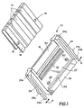
- Figures 3-5 show a second embodiment of a male connector, generally designated 10A, which is substantially identical to connector 10 (Figs. 1 and 2) except that connector 10A includes a resilient strain relief member 33 on the underside of flange 26 as best seen in Figure 5. Consequently, like numerals have been applied in Figures 3-5 designating like components of male connector 10A corresponding to the components described above in relation to connector 10 in Figures 1 and 2.
- flange 26 is a separate rigid plastic component joined to body member 22 by a living hinge 34.
- the living hinge is a molded-in-place component of elastomeric material such as silicone rubber.
- the opposite end of separate flange 26 has a hooked latch 35a for latching over a surface 35b of body member 22. Therefore, the flange can be unlatched to open slot 28 significantly to enable easy positioning of the flexible circuit in the slot.
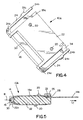
- Figure 5 clearly shows how resilient component 30 is molded-in-place about a leading edge 22a of body member 22. It also can be seen how flexible circuit 14 is wrapped around leading edge 16 of the connector defined by resilient component 30.
- the invention contemplates that locating holes 18 (Fig. 1) in flexible circuit 14 be spaced such that, when the holes are positioned about locating pegs 20 as seen in Figure 5, the flexible circuit will be wrapped tightly about resilient component 30, even to the extent of slightly compressing the resilient component in the direction of arrow "B". Therefore, the resilient component is effective to spring load the flexible circuit to enhance the engagement thereof with locating pegs 20. In other words, the resilient component is effective to take out any looseness or slack in the flexible circuit which, otherwise, might simply fall off of the locating pegs.
- a first length 14a of the circuit is disposed on top of body member 22, and a second length 14b of the circuit extends beneath flange 26 and away from the rear of the body member. It can be seen that the second length 14b of the circuit is in a plane offset from the plane of the first length 14a of the circuit.
- Resilient strain relief member 33 engages the top of length 14b of the circuit in its plane offset from length 14a of the circuit.
- resilient strain relief member 33 is a molded-in-place structure on the underside of flange 26 and is fabricated of such elastomeric material as silicone rubber.
- connector 10B for interconnecting the conductors 40 on opposite sides of a flat flexible circuit, generally designated 42, to the circuit traces on opposite sides of a printed circuit board 44 as seen in Figures 7 and 8.
- connector 10B includes a multi-part housing, generally designated 46, which is formed by a pair of rigid housing parts 48 and 50.
- Each housing part is a one-piece structure unitarily molded of dielectric material such as rigid plastic.
- the housing parts are movable between open positions shown in Figure 6 to facilitate loading of flexible circuit 42, and closed positions shown in Figures 7 and 8 for interconnecting the conductors of the flexible circuit to the circuit traces of printed circuit board 44.
- the housing parts have complementarily interengaging latch arms 52 which are flexible and molded integrally with the housing parts.
- the latch arms are cantilevered and include complementarily interengaging latch hooks 52a when the housing parts are in their closed positions.
- Housing part 50 has an elongated slot 54 for the passage therethrough of flexible circuit 42 as best seen in Figure 8.
- each housing part includes a resilient spring-loading component 30 at edges thereof about which the flexible circuit is wrapped similar to connectors 10 and 10A.
- the invention contemplates that relatively rigid plastic housing parts 48 and 50 be joined by flexible hinge means provided by a pair of molded-in-place hinge components 56.
- the hinge components are molded of elastomeric material such as silicone rubber. The hinge components accommodate movement of the rigid housing parts from their open positions shown in Figure 6 to their closed positions shown in Figures 7 and 8.
- FIG 8 shows how flexible circuit 42 is interconnected to printed circuit board 44 by connector 10B.
- flexible circuit 42 is a two-sided circuit in that it has conductors on both the top side 42a and the bottom side 42b as viewed in Figure 8.
- printed circuit board 44 will have circuit traces on both sides thereof.
- the flexible circuit is threaded through slot 54 in housing part 50, beneath the housing part and around resilient spring-loading member 30 at the leading edge of the housing part, whereupon bottom side 42b of the flexible circuit becomes the top side for engaging circuit traces on the bottom of printed circuit board 44.
- the circuit is wrapped about a rear edge 60 of housing part 48, over the top of the housing part, around resilient spring-loading component 30 at the front edge of the body part and into engagement with the top of printed circuit board 44.
- the top side 42a of the flexible circuit becomes the bottom side thereof for engaging the circuit traces on the top of the circuit board.
- Both housing parts 48 and 50 are shown in Figure 8 to include locating pegs 20 for insertion into appropriate locating holes in the flexible circuit to tightly wrap the circuit about resilient spring-loading members 30, as described above in relation to connectors 10 and 10A.
- Both housing parts 48 and 50 also include molded-in-place resilient backing structures 62 for biasing the flexible circuit against the top and bottom of the printed circuit board.
Landscapes
- Coupling Device And Connection With Printed Circuit (AREA)
- Multi-Conductor Connections (AREA)
Description
- This invention generally relates to the art of electrical connectors and, particularly, to connectors for electrically interconnecting flat flexible circuitry.
- A flat flexible circuit conventionally includes an elongated flat flexible dielectric substrate having laterally spaced strips of conductors on one or both sides thereof. The conductors may be covered with a thin, flexible protective layer on one or both sides of the circuit. If protective layers are used, cutouts are formed therein to expose the underlying conductors at desired contact locations where the conductors are to engage the conductors of a complementary mating connecting device which may be a second flat flexible circuit, a printed circuit board or the terminals of a mating connector.
- A wide variety of connectors have been designed over the years for terminating or interconnecting flat flexible circuits with complementary mating connecting devices. Major problems continue to plague such connectors, particularly in the area of cost and reliability. Not only is the direct material costs of such connectors unduly high, but an undue amount of labor time is required in assembling such connectors.
- US 5,009,607 discloses a flexible circuit connector according to the pre-characterizing portion of claim 1 which is used to electrically and mechanically connect a flexible circuit to a circuit board or other electronic device.The present invention is directed to solving these problems by providing an extremely simple, inexpensive and reliable connector structure not heretofore available.
- These problems are solved or at least ameliorated with a connector as defined in claim 1. In the exemplary embodiment of the invention, a newand improved connector is shown for electrically interconnecting the conductors of a flat flexible circuit to the conductors of a complementary mating connecting device. The connector includes a body member on which a first length of the flexible circuit is fixed, with a second length of the circuit extending away from the body member. A resilient strain relief means is provided on the body member engageable with the flexible circuit such as to locate the second length of the flexible circuit in a plane offset from the plane of the first length of the circuit. Therefore, pulling forces on the second length of the flexible circuit away from the body member biases the circuit against the resilient strain relief means.
- As disclosed herein, the body member includes a passage through which the second length of the flexible circuit extends. The passage is offset from the plane of the first length of the circuit. The resilient strain relief means is located in the passage. The body member is disposed herein as being elongated, and the passage is formed by a relatively narrow slot extending lengthwise of the body member.
- The body member is shown herein as a unitarily molded structure of plastic material, and the strain relief means is a molded-in-place component of an elastomeric material. The body member preferably is molded of relatively rigid plastic material, and the strain relief means may be of silicone rubber.
- The invention also contemplates the connector including a multi-part housing for receiving the flat flexible circuit. The housing includes at least a pair of rigid housing parts relatively movable between open and closed positions. A flexible hinge means is molded between the rigid housing parts to accommodate the movement of the housing parts between their positions. Like the resilient strain relief means, the flexible hinge means comprises at least one molded-in-place component of elastomeric material such as silicone rubber.
- Other objects, features and advantages of the invention will be apparent from the following detailed description taken in connection with the accompanying drawings.
- The features of this invention which are believed to be novel are set forth with particularity in the appended claims. The invention, together with its objects and the advantages thereof, may be best understood by reference to the following description taken in conjunction with the accompanying drawings, in which like reference numerals identify like elements in the figures and in which:
- FIGURE 1 is a top perspective view of a first embodiment of a connector incorporating the concepts of the invention;
- FIGURE 2 is a bottom perspective view of the connector of Figure 1;
- FIGURE 3 is a top perspective view of a second embodiment of the connector;
- FIGURE 4 is a bottom perspective view of the connector of Figure 3;
- FIGURE 5 is a section taken generally along line 5-5 of Figure 3;
- FIGURE 6 is a perspective view of a third embodiment of a connector incorporating the concepts of the invention, with the connector in open condition;
- FIGURE 7 is a perspective view of the connector of Figure 6 in closed condition, interconnecting a flexible circuit with a printed circuit board; and
- FIGURE 8 is a section taken generally along line 8-8 of Figure 7.
-
- Referring to the drawings in greater detail, and first to Figures 1 and 2, a first embodiment of a male connector, generally designated 10, is shown for electrically interconnecting the
conductors 12 of a flat flexible circuit orcable 14 to the conductors of a complementary mating connecting device (not shown). For instance,male connector 10 can be mated with a complementary female connector by inserting a leadingedge 16 of the male connector into an appropriate receptacle of the female connector. In some applications, the male connector could be connected to another complementary male connector. In these various applications, flatflexible circuit 14 is wrapped around leadingedge 16 of the connector, and locatingholes 18 in the circuit are positioned over locatingpegs 20 on opposite sides of the male connector. - More particularly,
male connector 10 includes amale body member 22 about which flatflexible circuit 14 is wrapped. The male body member is generally flat and elongated and includes a pair of cantileveredlatch arms 24 at opposite ends thereof. The body member, including the latch arms, is unitarily molded of relatively rigid dielectric material such as plastic or the like. Cantileveredlatch arms 24 are joined to the body member atproximal ends 24a of the latch arms near opposite ends of leadingedge 16 of the connector. Therefore,free ends 24b of the latch arms can flex in the direction of doubleheaded arrows "A". A pair oflatch hooks 24c project outwardly oflatch arms 24 for engagement with appropriate latch means on the complementary mating connecting device. Finally, a raised rib orflange 26 extends longitudinally along the top rear edge of the body member to define aslot 28 therebeneath and through which flatflexible circuit 14 extends, as best seen in Figure 5 described hereinafter. - Still referring to the embodiment of Figures 1 and 2, the invention contemplates the provision of resilient means in the form of an elongated
resilient component 30 which extends along and defines leadingedge 16 of the connector for spring loadingflexible circuit 14 to enhance the engagement thereof with locatingpegs 20.Resilient component 30 is a molded-in-place strip fabricated of elastomeric material, such as silicone rubber. - Finally, connector 10 (Figs. 1 and 2) includes a molded-in-place resilient backing rib 32 (Fig. 1) which extends longitudinally of the width of
body member 22 and engages the underside offlexible circuit 14 to biasconductors 12 of the circuit against the conductors of the complementary mating connecting device. - Figures 3-5 show a second embodiment of a male connector, generally designated 10A, which is substantially identical to connector 10 (Figs. 1 and 2) except that connector 10A includes a resilient strain relief member 33 on the underside of
flange 26 as best seen in Figure 5. Consequently, like numerals have been applied in Figures 3-5 designating like components of male connector 10A corresponding to the components described above in relation toconnector 10 in Figures 1 and 2. - Also in the embodiment of Figures 3 and 4,
flange 26 is a separate rigid plastic component joined tobody member 22 by aliving hinge 34. The living hinge is a molded-in-place component of elastomeric material such as silicone rubber. The opposite end ofseparate flange 26 has a hookedlatch 35a for latching over asurface 35b ofbody member 22. Therefore, the flange can be unlatched to openslot 28 significantly to enable easy positioning of the flexible circuit in the slot. - Before proceeding with a description of strain relief member 33, Figure 5 clearly shows how
resilient component 30 is molded-in-place about a leading edge 22a ofbody member 22. It also can be seen howflexible circuit 14 is wrapped around leadingedge 16 of the connector defined byresilient component 30. The invention contemplates that locating holes 18 (Fig. 1) inflexible circuit 14 be spaced such that, when the holes are positioned about locatingpegs 20 as seen in Figure 5, the flexible circuit will be wrapped tightly aboutresilient component 30, even to the extent of slightly compressing the resilient component in the direction of arrow "B". Therefore, the resilient component is effective to spring load the flexible circuit to enhance the engagement thereof with locatingpegs 20. In other words, the resilient component is effective to take out any looseness or slack in the flexible circuit which, otherwise, might simply fall off of the locating pegs. - Referring specifically to Figure 5, when
flexible circuit 14 is fully connected about eithermale connector 10 or 10A, a first length 14a of the circuit is disposed on top ofbody member 22, and asecond length 14b of the circuit extends beneathflange 26 and away from the rear of the body member. It can be seen that thesecond length 14b of the circuit is in a plane offset from the plane of the first length 14a of the circuit. Resilient strain relief member 33 engages the top oflength 14b of the circuit in its plane offset from length 14a of the circuit. Therefore, pulling forces on the flexible circuit in the direction of arrow "C" will have a tendency to bias the circuit against strain relief member 33 which is resilient and compressible to provide a degree of give or longitudinal movement to the circuit, rather than allowing all of the pulling forces to be translated directly to locatingpegs 20 at the top of the connector. Like resilient spring-loading component 30, resilient strain relief member 33 is a molded-in-place structure on the underside offlange 26 and is fabricated of such elastomeric material as silicone rubber. - Referring to Figures 6-8, a third embodiment of a connector, generally designated 10B, is shown for interconnecting the
conductors 40 on opposite sides of a flat flexible circuit, generally designated 42, to the circuit traces on opposite sides of a printedcircuit board 44 as seen in Figures 7 and 8. More particularly, connector 10B includes a multi-part housing, generally designated 46, which is formed by a pair ofrigid housing parts flexible circuit 42, and closed positions shown in Figures 7 and 8 for interconnecting the conductors of the flexible circuit to the circuit traces of printedcircuit board 44. The housing parts have complementarilyinterengaging latch arms 52 which are flexible and molded integrally with the housing parts. The latch arms are cantilevered and include complementarily interengaging latch hooks 52a when the housing parts are in their closed positions.Housing part 50 has an elongatedslot 54 for the passage therethrough offlexible circuit 42 as best seen in Figure 8. Finally, each housing part includes a resilient spring-loading component 30 at edges thereof about which the flexible circuit is wrapped similar toconnectors 10 and 10A. - The invention contemplates that relatively rigid
plastic housing parts place hinge components 56. The hinge components are molded of elastomeric material such as silicone rubber. The hinge components accommodate movement of the rigid housing parts from their open positions shown in Figure 6 to their closed positions shown in Figures 7 and 8. - Figure 8 shows how
flexible circuit 42 is interconnected to printedcircuit board 44 by connector 10B. More particularly,flexible circuit 42 is a two-sided circuit in that it has conductors on both thetop side 42a and thebottom side 42b as viewed in Figure 8. Correspondingly, printedcircuit board 44 will have circuit traces on both sides thereof. The flexible circuit is threaded throughslot 54 inhousing part 50, beneath the housing part and around resilient spring-loading member 30 at the leading edge of the housing part, whereuponbottom side 42b of the flexible circuit becomes the top side for engaging circuit traces on the bottom of printedcircuit board 44. Still referring to Figure 8, the circuit is wrapped about arear edge 60 ofhousing part 48, over the top of the housing part, around resilient spring-loading component 30 at the front edge of the body part and into engagement with the top of printedcircuit board 44. At this point of engagement, thetop side 42a of the flexible circuit becomes the bottom side thereof for engaging the circuit traces on the top of the circuit board. Bothhousing parts pegs 20 for insertion into appropriate locating holes in the flexible circuit to tightly wrap the circuit about resilient spring-loading members 30, as described above in relation toconnectors 10 and 10A. Bothhousing parts resilient backing structures 62 for biasing the flexible circuit against the top and bottom of the printed circuit board. - It will be understood that the invention may be embodied in other specific forms without departing from the central characteristics thereof. The present examples and embodiments, therefore, are to be considered in all respects as illustrative and not restrictive, and the invention is not to be limited to the details given herein.
Claims (19)
- A connector (10, 10A) for electrically interconnecting the conductors (12) of a flat flexible circuit (14) to the conductors of a complementary mating connecting device, comprising:characterized bya body member (22) on which a first length (14a) of the flexible circuit (14) is fixed, with a second length (14b) of the circuit (14) extending away from the body member; and
a resilient strain relief means (33) on the body member engageable with the flexible circuit (14) such as to locate the second length (14b) of the flexible circuit in a plane offset from the plane of the first length (14a) of the circuit,
whereby pulling forces on the second length (14b) of the flexible circuit (14) away from the body member (22) biases the circuit against the resilient strain relief means (33). - The connector of claim 1 wherein said body member includes a passage (28) through which the second length (14b) of the flexible circuit (14) extends, the passage being offset from the plane of the first length (14a) of the flexible circuit, and the resilient strain relief means (33) being located in the passage (28).
- The connector of claim 2 wherein said body member (22) is elongated, and said passage comprises a relatively narrow slot (28) extending lengthwise of the body member.
- The connector according to one of claims 1 to 3 wherein said body member (22) has a forward edge (22a) about which the flexible circuit (14) is wrapped, and said second length (14b) of the flexible circuit extends away from a rear portion of the body member.
- The connector according to one of claims 1 to 4 wherein said resilient strain relief means comprises a molded-in-place component (33).
- The connector of claim 5 wherein said body member (22) is unitarily molded of plastic material and said molded-in-place component (33) is of an elastomeric material.
- The connector according to one of claims 1 to 6 wherein said body member (22) is molded of relatively rigid plastic material.
- The connector according to one of claims 1 to 7 wherein said resilient strain relief means (33) is a silicone rubber structure.
- The connector (10, 10A) according to one of claims 1 to 8
wherein said strain relief means (33) comprises a resilient strain relief strip (33) molded-in-place on the body member (22) and being of an elastomeric material, the resilient strain relief strip (33) being engageable with the flexible circuit (14) such as to locate the second length (14b) of the flexible circuit in a plane offset from the plane of the first length (14a) of the circuit,
whereby pulling forces on the second length (14b) of the flexible circuit (14) away from the body member (22) biases the circuit against the resilient strain relief strip (33). - The connector of claim 9 wherein the slot is offset from the plane of the first length (14a) of the flexible circuit (14), and the resilient strain relief strip (33) is located in the slot (28).
- The connector (10, 10A) according to one of claims 1 to 10
wherein said body member (22) is a relatively rigid body member (22) on which the flexible circuit (14) is fixed, with a portion (14b) of the circuit extending away from the body member; and
said resilient strain relief means (33) is a molded strain relief means (33) biased against the flexible circuit (14) in response to pulling forces on said portion (14b) of the circuit away from the body member (22). - The connector (10, 10A) according to one of claims 1 to 11
wherein the body member comprises a multi-part housing (46) adapted to receive the flat flexible circuit (42) including at least a pair of rigid housing parts (48, 50) relatively movable between open and closed positions; and
a flexible hinge means (56) is molded between the rigid housing parts (48, 50) to accommodate said movement of the housing parts between said positions. - The connector of claim 12 wherein said flexible hinge means comprises at least one molded-in-place component (56).
- The connector of claim 12 or 13 wherein each of said housing parts (48, 50) is unitarily molded of plastic material.
- The connector according to one of claims 12 to 14 wherein said flexible hinge means (56) is of a silicone rubber material.
- The connector according to one of claims 12 to 15 wherein each of said housing parts (48, 50) is molded of relatively rigid plastic material.
- The connector according to one of claims 12 to 16 wherein said flexible hinge means comprise a pair of spaced hinge components (56).
- The connector of claim 17 wherein said pair of spaced hinge components comprise molded-in-place components (56) of elastomeric material.
- The connector of claim 18 wherein said hinge components (56) are of silicone rubber material.
Priority Applications (1)
| Application Number | Priority Date | Filing Date | Title |
|---|---|---|---|
| EP02012963A EP1249896A3 (en) | 1998-04-22 | 1999-04-14 | Electrical connector for flat flexible circuitry |
Applications Claiming Priority (2)
| Application Number | Priority Date | Filing Date | Title |
|---|---|---|---|
| US09/064,448 US6027363A (en) | 1998-04-22 | 1998-04-22 | Electrical connector for flat flexible circuitry |
| US64448 | 1998-04-22 |
Related Child Applications (1)
| Application Number | Title | Priority Date | Filing Date |
|---|---|---|---|
| EP02012963A Division EP1249896A3 (en) | 1998-04-22 | 1999-04-14 | Electrical connector for flat flexible circuitry |
Publications (3)
| Publication Number | Publication Date |
|---|---|
| EP0952630A2 EP0952630A2 (en) | 1999-10-27 |
| EP0952630A3 EP0952630A3 (en) | 2000-08-02 |
| EP0952630B1 true EP0952630B1 (en) | 2004-06-16 |
Family
ID=22056054
Family Applications (2)
| Application Number | Title | Priority Date | Filing Date |
|---|---|---|---|
| EP99107251A Expired - Lifetime EP0952630B1 (en) | 1998-04-22 | 1999-04-14 | Electrical connector for flat flexible circuitry |
| EP02012963A Withdrawn EP1249896A3 (en) | 1998-04-22 | 1999-04-14 | Electrical connector for flat flexible circuitry |
Family Applications After (1)
| Application Number | Title | Priority Date | Filing Date |
|---|---|---|---|
| EP02012963A Withdrawn EP1249896A3 (en) | 1998-04-22 | 1999-04-14 | Electrical connector for flat flexible circuitry |
Country Status (8)
| Country | Link |
|---|---|
| US (1) | US6027363A (en) |
| EP (2) | EP0952630B1 (en) |
| JP (1) | JP3205905B2 (en) |
| KR (1) | KR100296901B1 (en) |
| CN (1) | CN1116714C (en) |
| BR (1) | BR9901389A (en) |
| DE (1) | DE69917982T2 (en) |
| ES (1) | ES2218900T3 (en) |
Families Citing this family (27)
| Publication number | Priority date | Publication date | Assignee | Title |
|---|---|---|---|---|
| DE4329898A1 (en) | 1993-09-04 | 1995-04-06 | Marcus Dr Besson | Wireless medical diagnostic and monitoring device |
| FR2807220A1 (en) * | 2000-04-03 | 2001-10-05 | Raymond Bernier | Electrical flat cable/circuit board connection mechanism having outer flexible isolating shell sections stripped flat cable/board conductor plane pressing. |
| US6496705B1 (en) * | 2000-04-18 | 2002-12-17 | Motorola Inc. | Programmable wireless electrode system for medical monitoring |
| US6441747B1 (en) * | 2000-04-18 | 2002-08-27 | Motorola, Inc. | Wireless system protocol for telemetry monitoring |
| DE10034615C2 (en) * | 2000-07-17 | 2003-07-03 | Kostal Leopold Gmbh & Co Kg | Method for forming a plug connector from an electrical flat cable and plug connectors created by this method, as well as supporting bodies for forming such a plug connector |
| US6611705B2 (en) * | 2000-07-18 | 2003-08-26 | Motorola, Inc. | Wireless electrocardiograph system and method |
| FR2814864B1 (en) * | 2000-10-02 | 2005-01-14 | Fci Automotive France | DEVICE FOR MAINTAINING THE CRIMPING AREAS OF A FLEXIBLE CIRCUIT IN AN ELECTRICAL CONNECTOR AND THE EQUIPPED CONNECTOR |
| US7933642B2 (en) * | 2001-07-17 | 2011-04-26 | Rud Istvan | Wireless ECG system |
| JP2003031288A (en) * | 2001-07-18 | 2003-01-31 | Yazaki Corp | Flat circuit body and method for manufacturing the same |
| DE10250935B3 (en) * | 2002-10-31 | 2004-08-12 | Fci | Connector for flex ribbon cable |
| DE10350233A1 (en) * | 2003-10-27 | 2005-05-19 | Behr Gmbh & Co. Kg | Connector for joining consumer to bus system, for motor vehicle heating or air conditioning system, has flat cable contacting piece with electronic circuitry fixed in housing |
| US20070054544A1 (en) * | 2005-09-07 | 2007-03-08 | Toshihisa Hirata | Holder for flat flexible circuitry |
| US7387542B1 (en) * | 2007-06-07 | 2008-06-17 | Sony Corporation | HDMI connector |
| US7540752B1 (en) * | 2008-02-06 | 2009-06-02 | Tucker Timothy J | High conductor density connector for zero transmitted force engagement |
| FR2936658B1 (en) * | 2008-10-01 | 2013-01-18 | Axon Cable Sa | ASSEMBLY AND CONNECTION SYSTEM FOR CONNECTING A FLAT CABLE TO A BASE, AND METHOD FOR MANUFACTURING THE SAME |
| JP5312288B2 (en) * | 2009-10-27 | 2013-10-09 | ホシデン株式会社 | Shield case and connector provided with the same |
| JP5800597B2 (en) * | 2011-06-24 | 2015-10-28 | 矢崎総業株式会社 | Flat circuit assembly structure |
| JP5800598B2 (en) * | 2011-06-24 | 2015-10-28 | 矢崎総業株式会社 | Flat circuit assembly structure |
| JP6074711B2 (en) * | 2013-09-10 | 2017-02-08 | パナソニックIpマネジメント株式会社 | Cable holding member, electrical connection device, connector device |
| EP3026761A1 (en) * | 2014-11-27 | 2016-06-01 | odelo GmbH | Direct connection for electrically contacting flexible strip conductor holders in vehicle lights |
| US11217937B2 (en) | 2015-05-06 | 2022-01-04 | Lego A/S | Electrical connector and connector elements for a modular construction element and/or system |
| CN106007401A (en) * | 2016-05-16 | 2016-10-12 | 赛柏利安工业技术(苏州)有限公司 | Continuous magnetron sputtering deposition process of full-medium sunlight-selection vehicle window glass composite film series |
| CN106602304A (en) * | 2016-12-23 | 2017-04-26 | 青岛海信移动通信技术股份有限公司 | Terminal equipment |
| US10790608B2 (en) * | 2018-11-13 | 2020-09-29 | Mellanox Technologies, Ltd. | Apparatuses for improved cable-to-board connections |
| WO2021011486A1 (en) | 2019-07-16 | 2021-01-21 | Cellink Corporation | Terminal-free connectors and circuits comprising terminal-free connectors |
| WO2021011487A1 (en) * | 2019-07-16 | 2021-01-21 | Cellink Corporation | Terminal-free connectors and circuits comprising terminal-free connectors |
| JP7542397B2 (en) * | 2020-10-26 | 2024-08-30 | 株式会社ヨコオ | Plugs, Connectors and Receptacles |
Family Cites Families (12)
| Publication number | Priority date | Publication date | Assignee | Title |
|---|---|---|---|---|
| US3432794A (en) * | 1966-08-29 | 1969-03-11 | Thomas & Betts Corp | Card frame assembly |
| US3701071A (en) * | 1971-01-18 | 1972-10-24 | Berg Electronics Inc | Hinge type circuit board connector block |
| IT975428B (en) * | 1972-10-31 | 1974-07-20 | Fiat Spa | WATERPROOF CONNECTOR BETWEEN CABLES AND MOLDED CIR CUITS |
| US3989336A (en) * | 1975-04-28 | 1976-11-02 | Molex Incorporated | Flexible circuit connector assembly |
| US4770645A (en) * | 1983-08-05 | 1988-09-13 | Antes Jack E | Cable conductor to printed wiring board conductor clamp |
| US4740867A (en) * | 1987-03-26 | 1988-04-26 | Advanced Circuit Technology, Inc. | Printed circuit connection system |
| US5009607A (en) * | 1989-07-24 | 1991-04-23 | Rogers Corporation | Flexible circuit connector |
| US4975076A (en) * | 1990-03-01 | 1990-12-04 | Molex Incorporated | Contact wiping electrical connector |
| GB9100135D0 (en) * | 1991-01-04 | 1991-02-20 | Amp Great Britain | Electrical connector and an electrical contact element |
| US5145381A (en) * | 1991-08-22 | 1992-09-08 | Amp Incorporated | Wedge driven elastomeric connector |
| GB9221103D0 (en) * | 1992-10-07 | 1992-11-18 | Amp Holland | Electrical connector having improved strain relief |
| JP3362591B2 (en) * | 1996-02-23 | 2003-01-07 | 住友電装株式会社 | Flexible printed circuit board connector |
-
1998
- 1998-04-22 US US09/064,448 patent/US6027363A/en not_active Expired - Lifetime
-
1999
- 1999-04-13 JP JP10493499A patent/JP3205905B2/en not_active Expired - Fee Related
- 1999-04-14 ES ES99107251T patent/ES2218900T3/en not_active Expired - Lifetime
- 1999-04-14 EP EP99107251A patent/EP0952630B1/en not_active Expired - Lifetime
- 1999-04-14 DE DE69917982T patent/DE69917982T2/en not_active Expired - Fee Related
- 1999-04-14 EP EP02012963A patent/EP1249896A3/en not_active Withdrawn
- 1999-04-20 BR BR9901389-4A patent/BR9901389A/en not_active Application Discontinuation
- 1999-04-21 CN CN99105223A patent/CN1116714C/en not_active Expired - Fee Related
- 1999-04-21 KR KR1019990014320A patent/KR100296901B1/en not_active IP Right Cessation
Also Published As
| Publication number | Publication date |
|---|---|
| EP1249896A3 (en) | 2003-01-15 |
| EP0952630A2 (en) | 1999-10-27 |
| CN1233087A (en) | 1999-10-27 |
| BR9901389A (en) | 2000-01-18 |
| DE69917982T2 (en) | 2004-11-11 |
| JP3205905B2 (en) | 2001-09-04 |
| ES2218900T3 (en) | 2004-11-16 |
| KR100296901B1 (en) | 2001-07-12 |
| KR19990083381A (en) | 1999-11-25 |
| DE69917982D1 (en) | 2004-07-22 |
| EP1249896A2 (en) | 2002-10-16 |
| EP0952630A3 (en) | 2000-08-02 |
| US6027363A (en) | 2000-02-22 |
| JPH11329625A (en) | 1999-11-30 |
| CN1116714C (en) | 2003-07-30 |
Similar Documents
| Publication | Publication Date | Title |
|---|---|---|
| EP0952630B1 (en) | Electrical connector for flat flexible circuitry | |
| US6086412A (en) | Electrical connector for flat flexible circuitry | |
| US6039600A (en) | Male connector for flat flexible circuit | |
| US6077124A (en) | Electrical connectors for flat flexible circuitry with yieldable backing structure | |
| US20080261422A1 (en) | Flat Circuit Connector | |
| EP0963014B1 (en) | Electrical connector assembly for connecting flat flexible circuitry to discrete electrical terminals | |
| US5525072A (en) | Electrical connector assembly for interconnecting a flat cable to a circuit board | |
| US6244890B1 (en) | Male electrical connector for flat flexible circuit | |
| KR100403531B1 (en) | Electrical connector assembly for flat flexible circuitry | |
| US6036520A (en) | Electrical connector for flat circuitry | |
| US6726504B2 (en) | Electrical connector for connecting flat flexible circuitry to discrete terminal pins | |
| US6186811B1 (en) | Electrical connector for flat circuitry | |
| US6146171A (en) | Electrical connector for flat circuitry | |
| MXPA98008372A (en) | Connectors for circuiteria flexible pl |
Legal Events
| Date | Code | Title | Description |
|---|---|---|---|
| PUAI | Public reference made under article 153(3) epc to a published international application that has entered the european phase |
Free format text: ORIGINAL CODE: 0009012 |
|
| AK | Designated contracting states |
Kind code of ref document: A2 Designated state(s): DE ES FR IT |
|
| AX | Request for extension of the european patent |
Free format text: AL;LT;LV;MK;RO;SI |
|
| RIC1 | Information provided on ipc code assigned before grant |
Free format text: 7H 01R 12/08 A, 7H 01R 12/24 B |
|
| PUAL | Search report despatched |
Free format text: ORIGINAL CODE: 0009013 |
|
| AK | Designated contracting states |
Kind code of ref document: A3 Designated state(s): AT BE CH CY DE DK ES FI FR GB GR IE IT LI LU MC NL PT SE |
|
| AX | Request for extension of the european patent |
Free format text: AL;LT;LV;MK;RO;SI |
|
| 17P | Request for examination filed |
Effective date: 20010126 |
|
| AKX | Designation fees paid |
Free format text: DE ES FR IT |
|
| 17Q | First examination report despatched |
Effective date: 20010703 |
|
| GRAP | Despatch of communication of intention to grant a patent |
Free format text: ORIGINAL CODE: EPIDOSNIGR1 |
|
| GRAS | Grant fee paid |
Free format text: ORIGINAL CODE: EPIDOSNIGR3 |
|
| GRAA | (expected) grant |
Free format text: ORIGINAL CODE: 0009210 |
|
| AK | Designated contracting states |
Kind code of ref document: B1 Designated state(s): DE ES FR IT |
|
| REF | Corresponds to: |
Ref document number: 69917982 Country of ref document: DE Date of ref document: 20040722 Kind code of ref document: P |
|
| REG | Reference to a national code |
Ref country code: ES Ref legal event code: FG2A Ref document number: 2218900 Country of ref document: ES Kind code of ref document: T3 |
|
| ET | Fr: translation filed | ||
| PG25 | Lapsed in a contracting state [announced via postgrant information from national office to epo] |
Ref country code: IT Free format text: LAPSE BECAUSE OF NON-PAYMENT OF DUE FEES Effective date: 20050414 |
|
| PG25 | Lapsed in a contracting state [announced via postgrant information from national office to epo] |
Ref country code: ES Free format text: LAPSE BECAUSE OF NON-PAYMENT OF DUE FEES Effective date: 20050415 |
|
| PLBE | No opposition filed within time limit |
Free format text: ORIGINAL CODE: 0009261 |
|
| STAA | Information on the status of an ep patent application or granted ep patent |
Free format text: STATUS: NO OPPOSITION FILED WITHIN TIME LIMIT |
|
| 26N | No opposition filed |
Effective date: 20050317 |
|
| PGFP | Annual fee paid to national office [announced via postgrant information from national office to epo] |
Ref country code: FR Payment date: 20060417 Year of fee payment: 8 |
|
| PGFP | Annual fee paid to national office [announced via postgrant information from national office to epo] |
Ref country code: DE Payment date: 20060531 Year of fee payment: 8 |
|
| REG | Reference to a national code |
Ref country code: ES Ref legal event code: FD2A Effective date: 20050415 |
|
| PG25 | Lapsed in a contracting state [announced via postgrant information from national office to epo] |
Ref country code: DE Free format text: LAPSE BECAUSE OF NON-PAYMENT OF DUE FEES Effective date: 20071101 |
|
| PG25 | Lapsed in a contracting state [announced via postgrant information from national office to epo] |
Ref country code: FR Free format text: LAPSE BECAUSE OF NON-PAYMENT OF DUE FEES Effective date: 20070430 |