EP0042745B1 - Procédé pour faire fonctionner un moteur à combustion interne - Google Patents
Procédé pour faire fonctionner un moteur à combustion interne Download PDFInfo
- Publication number
- EP0042745B1 EP0042745B1 EP81302777A EP81302777A EP0042745B1 EP 0042745 B1 EP0042745 B1 EP 0042745B1 EP 81302777 A EP81302777 A EP 81302777A EP 81302777 A EP81302777 A EP 81302777A EP 0042745 B1 EP0042745 B1 EP 0042745B1
- Authority
- EP
- European Patent Office
- Prior art keywords
- hydrogen
- water
- duct
- vessel
- valve
- Prior art date
- Legal status (The legal status is an assumption and is not a legal conclusion. Google has not performed a legal analysis and makes no representation as to the accuracy of the status listed.)
- Expired
Links
Images


Classifications
-
- F—MECHANICAL ENGINEERING; LIGHTING; HEATING; WEAPONS; BLASTING
- F02—COMBUSTION ENGINES; HOT-GAS OR COMBUSTION-PRODUCT ENGINE PLANTS
- F02M—SUPPLYING COMBUSTION ENGINES IN GENERAL WITH COMBUSTIBLE MIXTURES OR CONSTITUENTS THEREOF
- F02M21/00—Apparatus for supplying engines with non-liquid fuels, e.g. gaseous fuels stored in liquid form
- F02M21/02—Apparatus for supplying engines with non-liquid fuels, e.g. gaseous fuels stored in liquid form for gaseous fuels
- F02M21/0218—Details on the gaseous fuel supply system, e.g. tanks, valves, pipes, pumps, rails, injectors or mixers
- F02M21/0227—Means to treat or clean gaseous fuels or fuel systems, e.g. removal of tar, cracking, reforming or enriching
-
- F—MECHANICAL ENGINEERING; LIGHTING; HEATING; WEAPONS; BLASTING
- F02—COMBUSTION ENGINES; HOT-GAS OR COMBUSTION-PRODUCT ENGINE PLANTS
- F02M—SUPPLYING COMBUSTION ENGINES IN GENERAL WITH COMBUSTIBLE MIXTURES OR CONSTITUENTS THEREOF
- F02M21/00—Apparatus for supplying engines with non-liquid fuels, e.g. gaseous fuels stored in liquid form
- F02M21/02—Apparatus for supplying engines with non-liquid fuels, e.g. gaseous fuels stored in liquid form for gaseous fuels
- F02M21/0203—Apparatus for supplying engines with non-liquid fuels, e.g. gaseous fuels stored in liquid form for gaseous fuels characterised by the type of gaseous fuel
- F02M21/0206—Non-hydrocarbon fuels, e.g. hydrogen, ammonia or carbon monoxide
-
- F—MECHANICAL ENGINEERING; LIGHTING; HEATING; WEAPONS; BLASTING
- F02—COMBUSTION ENGINES; HOT-GAS OR COMBUSTION-PRODUCT ENGINE PLANTS
- F02B—INTERNAL-COMBUSTION PISTON ENGINES; COMBUSTION ENGINES IN GENERAL
- F02B3/00—Engines characterised by air compression and subsequent fuel addition
- F02B3/06—Engines characterised by air compression and subsequent fuel addition with compression ignition
-
- F—MECHANICAL ENGINEERING; LIGHTING; HEATING; WEAPONS; BLASTING
- F02—COMBUSTION ENGINES; HOT-GAS OR COMBUSTION-PRODUCT ENGINE PLANTS
- F02M—SUPPLYING COMBUSTION ENGINES IN GENERAL WITH COMBUSTIBLE MIXTURES OR CONSTITUENTS THEREOF
- F02M21/00—Apparatus for supplying engines with non-liquid fuels, e.g. gaseous fuels stored in liquid form
- F02M21/02—Apparatus for supplying engines with non-liquid fuels, e.g. gaseous fuels stored in liquid form for gaseous fuels
- F02M21/0218—Details on the gaseous fuel supply system, e.g. tanks, valves, pipes, pumps, rails, injectors or mixers
- F02M21/023—Valves; Pressure or flow regulators in the fuel supply or return system
- F02M21/0242—Shut-off valves; Check valves; Safety valves; Pressure relief valves
-
- Y—GENERAL TAGGING OF NEW TECHNOLOGICAL DEVELOPMENTS; GENERAL TAGGING OF CROSS-SECTIONAL TECHNOLOGIES SPANNING OVER SEVERAL SECTIONS OF THE IPC; TECHNICAL SUBJECTS COVERED BY FORMER USPC CROSS-REFERENCE ART COLLECTIONS [XRACs] AND DIGESTS
- Y02—TECHNOLOGIES OR APPLICATIONS FOR MITIGATION OR ADAPTATION AGAINST CLIMATE CHANGE
- Y02T—CLIMATE CHANGE MITIGATION TECHNOLOGIES RELATED TO TRANSPORTATION
- Y02T10/00—Road transport of goods or passengers
- Y02T10/10—Internal combustion engine [ICE] based vehicles
- Y02T10/12—Improving ICE efficiencies
-
- Y—GENERAL TAGGING OF NEW TECHNOLOGICAL DEVELOPMENTS; GENERAL TAGGING OF CROSS-SECTIONAL TECHNOLOGIES SPANNING OVER SEVERAL SECTIONS OF THE IPC; TECHNICAL SUBJECTS COVERED BY FORMER USPC CROSS-REFERENCE ART COLLECTIONS [XRACs] AND DIGESTS
- Y02—TECHNOLOGIES OR APPLICATIONS FOR MITIGATION OR ADAPTATION AGAINST CLIMATE CHANGE
- Y02T—CLIMATE CHANGE MITIGATION TECHNOLOGIES RELATED TO TRANSPORTATION
- Y02T10/00—Road transport of goods or passengers
- Y02T10/10—Internal combustion engine [ICE] based vehicles
- Y02T10/30—Use of alternative fuels, e.g. biofuels
-
- Y—GENERAL TAGGING OF NEW TECHNOLOGICAL DEVELOPMENTS; GENERAL TAGGING OF CROSS-SECTIONAL TECHNOLOGIES SPANNING OVER SEVERAL SECTIONS OF THE IPC; TECHNICAL SUBJECTS COVERED BY FORMER USPC CROSS-REFERENCE ART COLLECTIONS [XRACs] AND DIGESTS
- Y10—TECHNICAL SUBJECTS COVERED BY FORMER USPC
- Y10S—TECHNICAL SUBJECTS COVERED BY FORMER USPC CROSS-REFERENCE ART COLLECTIONS [XRACs] AND DIGESTS
- Y10S123/00—Internal-combustion engines
- Y10S123/12—Hydrogen
Definitions
- the invention relates to fuel supply apparatus for an internal combustion engine, using hydrogen as a fuel, and to a method of operating an internal combustion engine using hydrogen as a fuel. It is applicable to both vehicle and stationary engines but is particularly suitable for stationary engines.
- fuel supply apparatus for an internal combustion engine comprises:
- the apparatus In use of the apparatus, it is preferred to supply only hydrogen and air to the engine, but supply of oxygen is optional for enhanced power output. For especially high outputs, the engine may be operated on hydrogen and oxygen, without air.
- the water supplying means comprises a water vessel and means for communicating between said water vessel and the reactor vessel for flow of water therethrough from said water vessel to the reactor vessel when the pressure in the reactor vessel is less than that in said water vessel.
- the means for communicating between said water vessel and the reactor vessel may comprise spray means disposed within the reactor vessel so that water flowing therethrough enters the reactor vessel in the form of a spray.
- each said valve means is an element of a proportioning valve and each of said elements of the proportioning valve comprises an apertured plate having a plurality of apertures in a portion thereof, and a masking plate having a window or windows therein, the window or windows having a total area at least equal to the area of said portion of the apertured plate, the masking plate and the apertured plate being movable relative to each other so that a selected number of the plurality of apertures may be aligned with the window or windows of the masking plate, each of said apertured plates having a different number of apertures, and the relative movement of the plates of each valve element being interlinked with the relative movement or movements of the plate or plates of the other or others of said valve elements so that the number of apertures of each apertured plate aligned with the window or windows of its corresponding masking plate is in a predetermined relationship with the number of correspondingly aligned apertures of the other or others of said apertured plates for each relative disposition of said plates.
- the hydrogen duct may comprise a presetting valve disposed downstream of the non-return valve with respect to the engine intake.
- the hydrogen plate has 24 apertures
- the air plate has 36 apertures
- the oxygen plate has 12 apertures, all of the apertures being of the same diameter.
- 4 hydrogen apertures, no oxygen apertures and all 36 air apertures are uncovered. If running on full oxygen, all 24 hydrogen apertures, all 12 oxygen apertures, but no air apertures, are uncovered. It will be appreciated that other constructions of this valve may be provided, or that the aperture ratios may be different.
- the proportioning valve serves to control at least in part the flow of hydrogen gas through the hydrogen duct in proportion to the flow of air through the air duct and/or in proportion to the flow of oxygen through the oxygen duct, the ratio of the quantity of hydrogen passing through the element of the proportioning valve in the hydrogen duct to the quantity of air and/or oxygen passing through the elements of the proportioning valve in the air and/or oxygen ducts respectively being determined at least in part by the number of apertures of the respective fixed plates aligned with the window openings of their corresponding movable masking plates. This ratio may be further controlled by the presetting valve, the presetting valve and the valve element of the proportioning valve in the hydrogen duct acting in series.
- the ratio of oxygen to hydrogen may be maintained in accordance with the relationship required for satisfactory operation of the engine through the full range of positions of the movable plates.
- the optimum percentage of hydrogen in a hydrogen/air mixture for fuel is 29.5% hydrogen. However, a hydrogen/oxygen mixture will explode for any proportion of hydrogen between 15% and 85%.
- the combination of proportioning and presetting valves allows full advantage to be taken of this latitude throughout the operating range of the engine.
- the range of the proportioning valve may be extended by governing at least the flow of hydrogen, and preferably also the flows of air and/or oxygen, by means of presetting valves.
- a particular function of the presetting valve is to ensure that hydrogen will be drawn into the apparatus during cranking for start-up. As soon as the engine fires, the presetting valves require further adjustment, since a start-up fuel mixture is too rich for normal running.
- the presetting valves are also operated to balance the flows when the engine is run on hydrogen and air without oxygen, or hydrogen and oxygen without air.
- a method of operating an internal combustion engine comprises the steps of:
- a particular advantage of the method and fuel supply apparatus according to the invention resides in the use of gaseous rather than liquid hydrogen, thus reducing the problems of storing the hydrogen and the weight of equipment required for this.
- the volatility of hydrogen gas since the hydrogen gas in the duct leading to the engine is at or below atmospheric pressure, the risk of a serious explosion due to blowback is minimised and additionally such danger may be further reduced by the provision of a side release on the vacuum valves, as described hereinafter.
- the fuel supply apparatus may form part of an installation in which wind or water power is used to produce hydrogen or to produce a material such as an alkali or alkaline earth metal from which hydrogen may be evolved, thus providing a means for storing energy generated by renewable energy sources.
- the intake of a spark- ignition internal combustion engine 1 is supplied with hydrogen in gaseous form evolved in a reactor 2 through a pipe or duct 3.
- a vacuum-operated non-return valve 4 with side release there are located, in order from the reactor, a presetting valve 5 and a proportioning valve 6, each of which will be described hereinafter.
- the hydrogen is produced by direct evolution through the chemical reaction of an alkali metal or an alkaline earth metal with water.
- Air may be supplied to the intake of the engine 1 from an air intake filter 7, through a pipe 8, in which a vacuum-operated non-return side release valve 9, similar to the valve 4 in the hydrogen line 3, and a presetting valve 10 are located.
- the pipe 8 then leads from the presetting valve 10 to the proportioning valve 6.
- the valves are again hereinafter described.
- An engine equipped with fuel supply apparatus according to the invention will operate satisfactorily on air alone, but additional power can be developed by the use of an additional oxygen supply.
- the engine will be described herein as operating with an oxygen supply as well as an air intake, but it will be appreciated that this is not an essential characteristic of the apparatus according to the invention. It will also be appreciated that in order to produce an especially high power output, the engine may be operated on hydrogen and oxygen alone.
- Oxygen is supplied to the intake of the engine 1 from a pressurised cylinder 12, provided with a cylinder valve 12a, through a pipe 11.
- the arrangement is generally similar to that for the hydrogen and air and includes a vacuum-operated non-return side release valve 13 and a presetting valve 14.
- the pipe 11 then leads from the presetting valve 14 to the proportioning valve 6.
- valves 4, 9 and 13 are vacuum-operated non-return valves, as described in connection with Fig. 3, and each has a side release or escape to cope with blowback from the engine.
- vacuum-operated refers to the operation of such valves by the presence of a region of low pressure on their downstream sides.
- valves of this type are known in themselves; the operating parts of the valve element include a portion of large area on the low-pressure or vacuum side, and a portion of lesser area on the high-pressure side, whereby the desired mode of operation is obtained.
- the valves 4 and 13 also effectively function as pressure reducing valves for the slightly pressurised gas generated in the reactor and the high-pressure gas supplied by the cylinder 12.
- a vacuum-operated non-return valve 4, 9 or 13 comprises a chamber 201 divided into two regions by a flexible diaphragm 202, the edge of which is secured to the wall of the chamber 201 in leak-proof manner.
- the chamber 201 has two parts which are clamped together to hold the diaphragm in position.
- the diaphragm carries a rigid plate 203 in a central portion thereof and the region above the diaphragm communicates with atmosphere through ports such as 214 in the wall of the chamber 201.
- the plate 203 engages the free end of a lever 204, the other end of which is pivoted at 205 to the wall of the chamber.
- the lever 204 is also pivoted to a shaft 206 which carries a closure member 207 adapted to close off the end of an inlet duct 215 when urged thereagainst.
- a spring 213 acting against a mounting member 212 fixed to the wall of the chamber serves to urge the member 207 to this closing position.
- the lever 204 is pivoted so as to move the closure member 207 away from the inlet 215 against the pressure of the spring.
- the plate 203 is moved downwardly with the diaphragm 202 when a vacuum is communicated to the lower region of the chamber 201 through outlet 208 so as to cause the diaphragm to move downwardly by the pressure of the atmosphere in the upper region of the chamber acting on the diaphragm.
- the side release element 209 consits of a rubber disc mounted on a stem 210 supported by a cross-piece 211 on the chamber wall, so that if a pressure greater than atmospheric is communicated to the valve through the outlet 208, it is immediately relieved through the side release to atmosphere. It will be clear that no air will be admitted through this element during normal operation of the valve. It will also be clear therefore that the valve 4, 9 or 13 functions as a demand valve and that the degree to which it opens depends on the level of vacuum communicated to the lower region of the chamber 201 through the outlet 208. Thus the more gas is required by the engine, the greater the vacuum communicated and the greater the flow therethrough to the engine. It will also be clear that the valve is adapted to function satisfactorily with a wide range of inlet pressures at the inlet 215.
- valves 4, 9 and 13 provide for the admission of gas through the inlet 215 when the pressure communicated to the outlet is less than atmospheric.
- valve can be modified, or an alternative construction provided, in which the pressure communicated to the outlet may exceed atmospheric, and that for the flow of gas, for example hydrogen, through the valve to the engine intake, all that is necessary is that pressure communicated to the outlet 208 should be less than that present at the inlet.
- the arrangement described has particular advantages, however, in that it provides added safety by virtue of the simple means for side release of gas to atmosphere in the event of blowback.
- the valves 5, 10 and 14 are presetting valves and are adjusted to control the vacuum applied to each of the valves 4, 9 and 13 when the proportioning valve 6 is set for starting, as will be hereinafter described. These valves also fulfil a flow control function, and are used in conjunction with the proportioning valve in the running condition of the engine, as will also be hereinafter described. It is preferred that these valves should be separate from the other valves of the apparatus, namely the non-return valves 4, 9 and 13, and the proportioning valve 6.
- the presetting valves are shown located between the non-return valves and the proportioning valve, but they could also be positioned on the engine intake side of the proportioning valve. In the present description, the presetting valves are referred to and shown as being arranged for continuous stepless variation of the opening thereof but in an alternative embodiment, stepwise opening of these valves is possible.
- the proportioning valve is shown in diagrammatic form in Fig. 2. It is a plate type valve and has three elements. Each element is associated with one of the pipes 3, 8 and 11, and thus handles hydrogen, oxygen or air respectively. Each element consists of a fixed plate 15, 17, 19 and a movable or front plate 16, 18, 20. The three movable plates are connected so that they move together. Each fixed plate 15, 17, 19 is provided with an array of holes 20a through which gas may pass. The number of holes in each of the fixed plates is different but the holes in all three plates are of the same size.
- Each movable plate 16, 18 and 20 is provided with a larger aperture or window 20b and according as the movable plate 16, 18 and 20 is moved relative to the corresponding fixed plate 15, 17 and 19, the holes 20a may be exposed or occluded to any required degree.
- Each of the windows 20b has a larger area than the area of the respective fixed plate 15, 17, 19 containing the array of holes 20a, so that all of the holes 20a in each fixed plate can be exposed.
- the valve elements thus control, in a precise manner, the quantities of gas and air flowing through them.
- the plates 15 and 16 control the flow of hydrogen, the plates 17 and 1 8 that of the oxygen, and the plates 19 and 20 the flow of the air. It will be seen from Fig. 2 that for every four holes 20a in the hydrogen plate 15, there are two holes in the oxygen plate 17 and six in the air plate 19, thus determining the balance between the three flows for each position of the movable plates, when the settings of the presetting valves are held constant.
- the three movable plates are operated by a single cable 21 connected to a bar 22 to which the plates 16, 18 and 20 are coupled.
- Springs 23 are attached to the lower ends of the plates 16, 18 and 20 to urge the plates towards the starting configuration shown.
- the cable 21 is coupled to the engine throttle control.
- presetting valves One function of the presetting valves is to ensure that hydrogen will be drawn past the non-return valve 4 under these start-up conditions. Without the presetting valves, the vacuum in the duct 3 would not be sufficient to cause the non-return valve to open, since the area of the proportioning valve open to air flow is so much greater than that provided for the flow of hydrogen under these starting conditions.
- the air presetting valve 10 is opened to a small extent and the hydrogen presetting valve 5 is opened to a larger extent.
- hydrogen is sucked into the fuel supply apparatus, when the engine is turned over, which may be by hand cranking or by an electric starter motor in conventional manner.
- the presetting valves require further adjustment, since the mixture is now too rich in hydrogen for normal running.
- the air presetting valve is opened more widely, or the hydrogen presetting valve is partly closed off, or both valves are simultaneously adjusted.
- the movable plates are moved upwards by means of the cable 21, so that the air holes are gradually closed off and the oxygen holes and more of the hydrogen holes are opened.
- the hydrogen and oxygen holes are opened to a greater degree, while the air holes are increasingly closed off.
- the oxygen presetting valve 14 may be fully closed, and the proportioning valve operated in a similar way to that employed when oxygen is being used along with air.
- oxygen is in use, either alone or with air, more hydrogen can be taken into the cylinder or cylinders of the engine than when the hydrogen is used with air alone, giving greater power and greater acceleration.
- the proportioning valve determines the ratio of hydrogen to oxygen in the mixture of hydrogen and/or air when the settings of the presetting valves are held constant, but adjustment of the degree of opening of these valves allows a further level of control of the quantities of these gases passing through the fuel supply apparatus.
- presetting valves could be combined with that of the proportioning valve.
- presetting valves suitable for stepwise operation and provided with arrays of apertures similar to the arrangements described for the proportioning valve may be employed.
- the presetting valves would be moved to a start-up position until the engine fired and then into an idling position as soon as it fired.
- a third position of the valves would be an accelerating and/or running position.
- a proportioning valve of the type herein described is precisely controllable to regulate the amounts of hydrogen and air and oxygen admitted to the engine.
- the degree of controllability is found to be superior to that obtainable with gate or needle type valves when dealing with gas flows.
- the valve has the further merits of simplicity and ease of manufacture.
- the interlinking of the elements of the proportioning valve may be achieved by means other than the mechanical construction described.
- the elements of the valve may be interlinked by electronic means adapted to control the respective flows of gas in the various ducts in the required proportions.
- the proportioning valve cannot be opened to its fullest extent when running on hydrogen and air only, since the hydrogen/oxygen ratio would not be maintained within the required limits, unless the presetting valves are also adjusted. It will also be realised that the degree of opening of the proportioning valve also affects the level of vacuum applied to the valves 4, 9 or 13, and thus also determines the demand for the gases at these valves, within the overall demand created at the engine intake. As more of the holes in the plates are uncovered, the level of the vacuum at the valves 4, 9, 13 is increased.
- the engine itself is not radically changed from its configuration when using oil as a fuel.
- the carburettor is removed and replaced by the hydrogen/oxy- gen/air supply apparatus described hereinabove, but the ignition system, including the spark plugs and associated electrical equipment, and the valve system of the engine proper are unaltered in principle although it may be necessary to make adjustments in the engine timing and/or valve settings. It is envisaged that an engine equipped with fuel supply apparatus according to the invention would be particularly suitable for an electronic timing system.
- Hydrogen for operating an internal combustion engine according to the method of the invention is produced by using the chemical reaction between an alkali metal or an alkaline earth metal and water.
- the reaction between the water and the alkali metal or alkaline earth metal liberates hydrogen, but oxygen gas is not produced.
- the water may require to be heated.
- a vessel 39 provided with a water pipe 40 connecting it to a further vessel 41 and having a hydrogen outlet 42, contains a stainless steel wire mesh cage 43 within which a portion of an alkali metal or an alkaline earth metal may be placed.
- the cage 43 has a removable top 43a secured by wing nuts 43b.
- the cage 43 is suitably located approximately midway between the top and bottom of the vessel 39.
- the vessel 39 may be substantially cylindrical and its top portion 39a is removable to give access to the cage 43.
- the top portion of the vessel is also secured in position by wing nuts 39b, and includes a safety valve 44, and a pressure gauge 44a.
- the further vessel 41 is also preferably cylindrical, and is closed, apart from an outlet/inlet pipe 62 which ends at an adjustable pressure release valve 63 and has a branch pipe 64 ending at a non-return valve 65 adapted to admit air and/or water to the pipe 64 and vessel 41.
- the vessels 39 and 41 are initially empty of water so that the vessel 39 can be opened, the stainless steel wire mesh cage also opened and the alkali metal or alkaline earth metal placed within the cage.
- the top portion of the cage is then re-secured using the wing nuts 43b and the top portion of the vessel 39 is similarly set back in place and fastened in position by means of the wing nuts 39b.
- the hydrogen outlet is connected to the intake of an internal combustion engine via the pipe 3 of Fig. 1, through the non-return valve, the presetting valve and the proportioning valve.
- the vessels 39 and 41 are then charged with water.
- the level of the water in the vessel 41 is controlled by the setting of the pressure release valve 63, which thus also controls the water level in the vessel 39, since the two vessels are connected by the pipe 40.
- the water level in the vessel 39 rises, the water comes into contact with the alkali metal or alkaline earth metal within the cage 43.
- valve 63 As the water level in the vessel 41 rises, the air above it is compressed. If the air pressure exceeds the setting of the valve 63, the pressure is relieved by the valve. Air blowing off from valve 63 may be led away through a branch pipe 66 which may exhaust to atmosphere, or over a water tray or vessel.
- the pressure in the vessel 39 falls. With the drop in pressure, the water level can rise again in the vessel 39, as explained below, so that the water again comes into contact with the metal in the cage, and more hydrogen is given off.
- the non-return valve 65 at the end of the branch pipe 64 allows the water level in the vessel 39 to rise, by admitting air to the vessel 41 above the level of the water in that vessel, when the pressure above the water in the vessel falls below atmospheric.
- the non-return valve may be arranged to be below, at least some of the time, the surface of water or condensate in a suitable tray or vessel, so that the water or condensate is sucked into the vessel 41 by a negative pressure therewithin.
- the branch pipe 66 may also end above the tray so that any water expelled from the vessel 41 during the evolution of hydrogen in vessel 39 can be returned to be taken into the vessel again when there is a negative pressure within it.
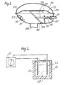
- FIG. 7 An alternative embodiment of the reactor 2 is shown in Fig. 7.
- the arrangement is in many respects similar to that of Figs. 5 and 6 but the hydrogen is evolved by spraying water onto the alkali or alkaline earth metal contained in the cage, rather than by immersing the metal in water, as is the case in the previously described embodiment.
- Those items in Fig. 7 which are substantially identical with items in Figs. 5 and 6 are distinguished by the use of the same identifying numerals, with the addition of one hundred in each case.
- a pressure vessel 250 contains water and is charged to an outlet pressure determined by the pressure which the spray is required to overcome in the vessel 139.
- the vessel 250 is provided with a pressure gauge 251 and an inlet 252, through which it may be charged with water and pressurised.
- a pump may be used, which is adjusted and controlled to feed water at a predetermined pressure to the vessel 139.
- a pipe 253 connects the pressure vessel 250 to the vessel 139, where it terminates in a nozzle device 254, adapted to spray water received through the pipe under pressure from the pressure vessel 250, onto the alkali or alkaline earth metal contained in the cage 143.
- a valve 255 in the pipeline 253 controls the flow of water through the pipe.
- the vessel 139 contains a body of water and is connected by pipe 140 to the vessel 141, similarly to the arrangement shown in Fig. 5. While the presence of water in large quantity in the vessel 139 is not essential with the spray arrangement of Fig. 7, a certain amount is required in order to dilute the concentrated hydroxide resulting from the reaction of metal and the water.
- the operating pressure of the vessel 139 is low, and may be of the order of five to ten psi (34 to 69 kN/m 2 ). Actual operating pressures will depend on the design of the reactor vessel and the hydrogen demand. This embodiment of the reactor facilitates control of the rate of evolution of the hydrogen, which is especially advantageous in situations where demand varies rapidly.
- the evolution of the hydrogen in the reactor is accompanied by the generation of a considerable amount of heat.
- a condenser 256 cooled by water in the line 142 leading from the vessel 139.
- the condenser is followed by a water trap.
- the condenser includes a coil through which the gas passes and a water jacket and is of known design which will not be described further.
- a water jacket 257 is also provided on the vessel 139.
- the exhaust line from the engine may also include a water cooler, so that the heat from all of these jackets and coolers may be collected in a single hot water circuit.
- the water from the condenser 256 is first directed to the exhaust gas cooler and thereafter to the cooling jacket on the reactor vessel 139.
- the heat may be used for space heating or for supplying hot water.
- the heat can be liberated in the form of steam, and may possibly be used to drive a small turbine.
- the alkali metal or alkaline earth metal may, in addition to the cage arrangements described above or in part replacement of them, be fully encased in a water soluble material or encased in a material insoluble in water but having holes in it to admit water to the encased metal. By this means an additional or alternative control may be imposed on the rate at which the hydrogen gas is evolved.
- Fig. 8 shows a modified version of the hydrogen line 3 of Fig. 1 continuing from the line VIII-Vill in Figs. 5 or 7.
- the hydrogen line includes various elements not included in Fig. 1, mainly directed towards drying the hydrogen en route to the engine 1.
- the hydrogen passes through a trap 54, intended to remove water from it, and then through a dryer 55, which contains a quantity of desiccating material.
- Valve 56 is a vacuum operated side release safety valve and is followed by the presetting valve 5 and the proportioning valve 6 as shown in Fig. 1.
- Fig. 9 shows one form of non-return valve for preventing carry-over of water from the vessel 39 of Fig. 5 into the line 3 which can occur in operation of the engine in the event of a sudden surge or demand for gas.
- a ball valve element 58 is mounted on a rod 59 extending from a float element 60 on the surface of the water in the vessel and is guided and restrained in vertical movement towards and away from the outlet 42 by guides 61. Thus if the water level rises beyond a predetermined amount, the ball 58 closes off the outlet 42 and stops flow of gas until the surge has ceased. In this way the line 3 and the valve associated with it are protected from flooding and possible damage by the water.
- FIGs. 8 and 9 represent only one method of embodying the features shows therein and that other equivalent means may be employed within the scope of the invention.
- valve 53 in the pipe 40 connecting the vessels 39 and 41.
- This valve serves to drain the water from the reactor vessels when it is not desired to generate hydrogen and it may lead to a drain compartment or vessel for the water. It also fulfils a safety function in that it can act as a dump valve to drain the reactor vessels rapidly in the event of any untoward circumstance which requires urgent cessation of the evolution of hydrogen. It can thus be coupled to an emergency button or lever available to the operator or driver.
- a similar safety feature can be included in the reactor of Fig. 7 for rapid release of the pressure in the vessel 250.
- water in the exhaust from the engine can be condensed and the condensed water directed back to the vessel 41 or 141 so that the water system of the reactor is closed, and the water in it is continuously recycled.
- the condensate can be pumped back to the vessel 41 or 141 or can flow under gravity if the condenser is disposed at a higher level than the vessel.
- the exhaust line condenser may additionally serve to clear the exhaust more effectively by causing a relative vacuum in the exhaust line.
- Fig. 10 shows a suitable form of exhaust line condenser.
- the exhaust gases enter condenser 67 via inlet 68 and flow through it to outlet 69.
- baffles 71 disposed transversely across the condenser.
- the holes 70 are disposed either in the upper or lower part of each baffle, each baffle with the holes 70 in its upper part being followed by one with the holes in its lower part, so as to promote condensation of water vapour in the exhaust.
- Each baffle 71 also has an opening 72 at its bottom part to allow condensed water vapour to flow to a condensate outlet 73.
- Fig. 4 shows a system for producing an alkali metal or alkaline earth metal by electrolysis of the fused chloride of the metal required, with small quantities of another alkali or alkaline earth metal chloride added in order to reduce the melting point.
- a cathode 53 of iron and an anode 54 of carbon are used, and are placed in the fused chloride 55 to which is added the other alkali or alkaline earth metal chloride.
- the mixture is contained in a heated and insulated vessel 56 and a d.c. source 57 is placed across the electrodes.
- a d.c. source 57 is placed across the electrodes.
- the method of generating hydrogen involving the use of an alkali or alkaline earth metal is envisaged as suitable for use in conjunction with electricity generation using renewable sources of energy, e.g. wind, small scale water generation, and solar voltaic cells.
- renewable energy sources e.g. wind, small scale water generation, and solar voltaic cells.
- a major disadvantage of renewable energy sources is the difficulty of storing surplus energy, e.g. energy collected by a solar panel on a hot sunny day, for use on subsequent occasions, e.g. on a cold day.
- the most commonly used known method is by means of storage batteries, but this is cumbersome, expensive and not wholly satisfactory.
- the apparatus and method described herein allow the conversion of such surplus energy for known internal combustion engines, either immediately or on some later occasion, thus providing convenient and safe storage of the energy.
- the surplus energy generated may be used for electrolysis of fused chlorides to produce alkali or alkaline earth metals for later use to produce hydrogen for direct use in an engine.
- a renewable energy generator such as a windmill may be used to supply power and regenerate alkali metal.
- the alkali metal may be used to produce hydrogen to drive an engine as described hereinabove.
- the wind generator operates with a diesel generator, the latter comprising for the fluctuations in output resulting from changing wind conditions.
- the wind generator can be deployed for regenerating the alkali or alkaline earth metal only, and power can be generated by the hydrogen gas produced by the reaction of the metal and water. Thus the load fluctuation problems are avoided.
- waste in the system is reduced, and the advantages are enhanced when the necessary energy input is obtained from a renewable resource.
- a suitable metal is lithium, which is available in reasonable abundance. However, since it will be continually recycled and serve as an energy carrier, rather than as a consumable material, its relative scarcity or abundance is not of prime importance. It has the particular advantage that it is relatively non-inflammable in air, unlike sodium and potassium which are thus more difficult to handle.
Landscapes
- Engineering & Computer Science (AREA)
- Chemical & Material Sciences (AREA)
- Chemical Kinetics & Catalysis (AREA)
- General Chemical & Material Sciences (AREA)
- Oil, Petroleum & Natural Gas (AREA)
- Combustion & Propulsion (AREA)
- Mechanical Engineering (AREA)
- General Engineering & Computer Science (AREA)
- Output Control And Ontrol Of Special Type Engine (AREA)
Claims (9)
caractérisé en ce que le dispositif générateur d'hydrogène gazeux comprend une cuve de réacteur propre à recevoir une certaine quantité d'un métal alcalin ou d'un métal alcalino- terreux et un dispositif pour fournir de l'eau au métal en vue de produire de l'hydrogène gazeux par réaction du métal avec l'eau, le dispositif d'alimentation d'eau réagissant aux variations de la pression de gaz dans la cuve de réacteur, une valve de retenue actionnée par dépression est prévue pour admettre l'hydrogène de la cuve de réacteur par le conduit d'hydrogène lorsque la pression à l'admission du moteur est inférieure à la pression de gaz dans la cuve de réacteur, et chaque valve de réglage est reliée à l'autre valve de réglage ou aux autres valves de réglage de telle sorte que le débit de l'hydrogène gazeux passant dans le conduit d'hydrogène puisse être réglé proportionnellement au débit d'air passant par le conduit d'air et/ou au débit d'oxygène passant par le conduit d'oxygène.
caractérisé en ce qu'on produit l'hydrogène gazeux en fournissant de l'eau à une certaine quantité d'un métal alcalin ou d'un métal alca- lino-terreux dans la cuve de réacteur, l'alimentation d'eau réagissant aux variations de la pression de gaz dans la cuve du réacteur, on admet l'hydrogène gazeux produit par le conduit d'hydrogène et par une valve de retenue actionnée par dépression lorsque la pression à l'admission du moteur est inférieure à la pression du gaz dans la cuve de réacteur d'hydrogène, et chaque valve de réglage est reliée à l'autre valve de réglage ou aux autres valves de réglage de telle sorte que le débit de l'hydrogène gazeux passant dans le conduit d'hydrogène soit réglé proportionnellement au débit d'air passant par le conduit d'air et/ou au débit d'oxygène passant par le conduit d'oxygène.
Priority Applications (1)
| Application Number | Priority Date | Filing Date | Title |
|---|---|---|---|
| AT81302777T ATE10606T1 (de) | 1980-06-20 | 1981-06-19 | Verfahren zum betrieb eines verbrennungsmotors. |
Applications Claiming Priority (4)
| Application Number | Priority Date | Filing Date | Title |
|---|---|---|---|
| IE129280A IE51181B1 (en) | 1981-05-14 | 1980-06-20 | Method of operating an i.c.engine |
| IE129280 | 1980-06-20 | ||
| IE107981 | 1981-05-14 | ||
| IE107981 | 1981-05-14 |
Publications (2)
| Publication Number | Publication Date |
|---|---|
| EP0042745A1 EP0042745A1 (fr) | 1981-12-30 |
| EP0042745B1 true EP0042745B1 (fr) | 1984-12-05 |
Family
ID=26319042
Family Applications (1)
| Application Number | Title | Priority Date | Filing Date |
|---|---|---|---|
| EP81302777A Expired EP0042745B1 (fr) | 1980-06-20 | 1981-06-19 | Procédé pour faire fonctionner un moteur à combustion interne |
Country Status (4)
| Country | Link |
|---|---|
| US (1) | US4411223A (fr) |
| EP (1) | EP0042745B1 (fr) |
| CA (1) | CA1166098A (fr) |
| DE (1) | DE3167585D1 (fr) |
Families Citing this family (18)
| Publication number | Priority date | Publication date | Assignee | Title |
|---|---|---|---|---|
| GB8500064D0 (en) * | 1985-01-03 | 1985-02-13 | Thomas I | Electrolysis unit |
| US5117783A (en) * | 1991-11-04 | 1992-06-02 | Antonio Robinson | Automatic oxygen generator |
| US5231954A (en) * | 1992-08-05 | 1993-08-03 | J. C. Conner | Hydrogen/oxygen fuel cell |
| ITTO20010276A1 (it) * | 2001-03-23 | 2002-09-23 | Fiat Ricerche | Sistema per la diagnostica di perdite da un impianto di alimentazionea gas e per la verifica del funzionamento delle valvole facenti parte |
| DE10206034A1 (de) * | 2002-02-14 | 2003-08-21 | Bayerische Motoren Werke Ag | Einrichtung zum Einbringen von Kraftstoff zur Verbrennung in einer Brennkraftmaschine |
| AU2003215877A1 (en) * | 2002-03-18 | 2003-09-29 | Engineuity Research & Development Ltd | A closed loop energy system for power generation and transportation based on metal fuel and condensed phase oxidizer |
| US6923168B2 (en) * | 2003-02-10 | 2005-08-02 | Power-One As | Fuel control system and method for distributed power generation, conversion, and storage system |
| CA2576682A1 (fr) * | 2006-03-08 | 2007-09-08 | Martinrea International Inc. | Systeme d'application d'electrolyte |
| US8336508B2 (en) * | 2008-09-17 | 2012-12-25 | Timothy Huttner | System and method for use with a combustion engine |
| US8528504B2 (en) | 2010-08-08 | 2013-09-10 | Eduardas Ceremis | Internal combustion engine enhancement device and method |
| WO2012021426A2 (fr) * | 2010-08-11 | 2012-02-16 | Eduardas Ceremis | Dispositif permettant d'améliorer la performance d'un moteur à combustion interne |
| AT511863B1 (de) * | 2011-09-12 | 2013-10-15 | Klaar Alfred | Kolbenmaschine und verfahren zum betrieb einer kolbenmaschine |
| US8739743B2 (en) * | 2012-03-27 | 2014-06-03 | Go Green Hybrid Fuel Systems | Hydrogen feed method and systems for engines |
| WO2017165799A1 (fr) * | 2016-03-24 | 2017-09-28 | Beckman Michael Manford | Interface de communication entre un système de commande d'émission et un moteur à combustion interne |
| KR200493039Y1 (ko) * | 2017-09-22 | 2021-01-21 | 수엡퐁 차리타폰 | 수소 가스를 발생시켜 내연 엔진으로 공급하기 위한 시스템 |
| DE102019128882B3 (de) | 2019-10-25 | 2020-12-17 | Fraunhofer-Gesellschaft zur Förderung der angewandten Forschung e.V. | Verfahren zur prozessintegrierten Sauerstoff-Versorgung eines Wasserstoff-Kreislaufmotors mit Kreislaufführung eines Edelgases |
| JP6825150B1 (ja) * | 2019-10-30 | 2021-02-03 | 株式会社Hit研究所 | エンジンへの水素ガス供給システム |
| US11492938B2 (en) | 2020-02-28 | 2022-11-08 | Applied Resonance Technology Llc | Carbon capture in an internal combustion engine |
Family Cites Families (15)
| Publication number | Priority date | Publication date | Assignee | Title |
|---|---|---|---|---|
| US3862624A (en) * | 1970-10-10 | 1975-01-28 | Patrick Lee Underwood | Oxygen-hydrogen fuel use for combustion engines |
| US3799124A (en) * | 1972-05-05 | 1974-03-26 | Pollution Free Power Corp | Hydrogen engine and method of fueling same |
| US4189916A (en) * | 1972-10-27 | 1980-02-26 | Skala Stephen F | Vehicle system for NaK-water-air internal combustion engines |
| US3818875A (en) * | 1972-11-30 | 1974-06-25 | E Phillips | Pollution-free combustion engine and unique fuel therefor |
| US3977365A (en) * | 1973-08-06 | 1976-08-31 | Vierling Donald E | Method of oxidizing fuels |
| DE2360568A1 (de) * | 1973-12-05 | 1975-06-19 | Udo Studenski | Verfahren zu betreibung eines verdichtermotors als verbrennungsdampfmaschine |
| US3946711A (en) * | 1974-04-08 | 1976-03-30 | Wigal Voorhis F | Hydrogen fired ignition system for internal combustion engines |
| US4016836A (en) * | 1975-09-08 | 1977-04-12 | Billings Energy Research Corporation | Hydride fuel system |
| US4103653A (en) * | 1975-11-28 | 1978-08-01 | Nissan Motor Company, Limited | Method of and apparatus for controlling ignition timing of an internal combustion engine |
| CH597091A5 (en) * | 1976-09-06 | 1978-03-31 | Andre Auroy | Hydrogen and steam generating appts. |
| US4141326A (en) * | 1977-03-11 | 1979-02-27 | The Bendix Corporation | Closed loop control system for hydrogen fuelled engine |
| DE2810913A1 (de) * | 1978-03-14 | 1979-09-27 | Licentia Gmbh | Anlage und verfahren zur gewinnung von wasserstoff |
| GB2029447B (en) * | 1978-08-23 | 1982-09-15 | Taylor T | Apparatus for providing a mixture of hydrogen and oxygen for an engine |
| DE2856276C2 (de) * | 1978-12-15 | 1982-12-23 | Kernforschungsanlage Jülich GmbH, 5170 Jülich | Verfahren zur Stromausbeutesteigerung einer Schmelzflußelektrolyse mit anodischer Sauerstoffentwicklung |
| GB2039528B (en) * | 1978-12-15 | 1982-11-03 | Kernforschungsanlage Juelich | Increasing current yield in molten elecrtrolyte electrolysis |
-
1981
- 1981-06-19 CA CA000380258A patent/CA1166098A/fr not_active Expired
- 1981-06-19 US US06/275,512 patent/US4411223A/en not_active Expired - Fee Related
- 1981-06-19 EP EP81302777A patent/EP0042745B1/fr not_active Expired
- 1981-06-19 DE DE8181302777T patent/DE3167585D1/de not_active Expired
Also Published As
| Publication number | Publication date |
|---|---|
| EP0042745A1 (fr) | 1981-12-30 |
| CA1166098A (fr) | 1984-04-24 |
| US4411223A (en) | 1983-10-25 |
| DE3167585D1 (en) | 1985-01-17 |
Similar Documents
| Publication | Publication Date | Title |
|---|---|---|
| EP0042745B1 (fr) | Procédé pour faire fonctionner un moteur à combustion interne | |
| US4606319A (en) | System and method of vaporizing liquid fuel for delivery to an internal combustion engine | |
| US4111160A (en) | Method and apparatus for operating combustion engines | |
| CN102007271B (zh) | 内燃机 | |
| US3565201A (en) | Cryogenic fuel system for land vehicle power plant | |
| US20080110421A1 (en) | Hydrogen Fuel System for an Internal Combustion Engine | |
| US6511052B1 (en) | Humidifying gas induction or supply system | |
| WO2015070802A1 (fr) | Système et procédé de production d'électricité en utilisant de l'hydrogène préparé instantanément | |
| JPH11501378A (ja) | 触媒コンバータを加熱してエミッションを低減するための方法及び装置 | |
| CA1125478A (fr) | Methode et systeme auto-regenere d'extraction d'oxygene et d'eau constituant des impuretes dans l'hydrogene gazeux | |
| US7021272B2 (en) | Computer controlled multi-stroke cycle power generating assembly and method of operation | |
| CN103867352A (zh) | 一种节能助燃车载氢氧发生系统 | |
| CN104564438B (zh) | 高热效醇类发电机组 | |
| US4632067A (en) | Vapor injection device | |
| US4444159A (en) | Calcium carbide/water acetylene gas generator | |
| CA1071950A (fr) | Methode et accessoire de combustion pour moteur a combustion interne | |
| US20100122902A1 (en) | System for the electrolytic production of hydrogen as a fuel for an internal combustion engine | |
| IE51181B1 (en) | Method of operating an i.c.engine | |
| WO2020243980A1 (fr) | Système de sortie de puissance aérodynamique continue | |
| US4741156A (en) | Process for igniting a regenerative soot filter in the exhaust gas connection of diesel engines | |
| WO2016029603A1 (fr) | Système et procédé permettant une intégration de la production d'électricité et de la réfrigération d'automobile | |
| EA009651B1 (ru) | Способ и устройство для превращения смеси воды и этилового спирта в топливо | |
| CN100341190C (zh) | 自产氢气的水下运载器燃料电池与空气调节联合系统 | |
| CN2227744Y (zh) | 环保加水引擎发动机 | |
| GB2143848A (en) | Gas generation and control system for an engine |
Legal Events
| Date | Code | Title | Description |
|---|---|---|---|
| PUAI | Public reference made under article 153(3) epc to a published international application that has entered the european phase |
Free format text: ORIGINAL CODE: 0009012 |
|
| AK | Designated contracting states |
Designated state(s): AT BE CH DE FR GB IT LU NL SE |
|
| 17P | Request for examination filed |
Effective date: 19820605 |
|
| GRAA | (expected) grant |
Free format text: ORIGINAL CODE: 0009210 |
|
| AK | Designated contracting states |
Designated state(s): AT BE CH DE FR GB IT LI LU NL SE |
|
| PG25 | Lapsed in a contracting state [announced via postgrant information from national office to epo] |
Ref country code: SE Effective date: 19841205 Ref country code: NL Effective date: 19841205 Ref country code: LI Effective date: 19841205 Ref country code: IT Free format text: LAPSE BECAUSE OF FAILURE TO SUBMIT A TRANSLATION OF THE DESCRIPTION OR TO PAY THE FEE WITHIN THE PRESCRIBED TIME-LIMIT;WARNING: LAPSES OF ITALIAN PATENTS WITH EFFECTIVE DATE BEFORE 2007 MAY HAVE OCCURRED AT ANY TIME BEFORE 2007. THE CORRECT EFFECTIVE DATE MAY BE DIFFERENT FROM THE ONE RECORDED. Effective date: 19841205 Ref country code: FR Free format text: THE PATENT HAS BEEN ANNULLED BY A DECISION OF A NATIONAL AUTHORITY Effective date: 19841205 Ref country code: CH Effective date: 19841205 Ref country code: BE Effective date: 19841205 Ref country code: AT Effective date: 19841205 |
|
| REF | Corresponds to: |
Ref document number: 10606 Country of ref document: AT Date of ref document: 19841215 Kind code of ref document: T |
|
| REF | Corresponds to: |
Ref document number: 3167585 Country of ref document: DE Date of ref document: 19850117 |
|
| NLV1 | Nl: lapsed or annulled due to failure to fulfill the requirements of art. 29p and 29m of the patents act | ||
| PG25 | Lapsed in a contracting state [announced via postgrant information from national office to epo] |
Ref country code: LU Free format text: LAPSE BECAUSE OF NON-PAYMENT OF DUE FEES Effective date: 19850630 |
|
| EN | Fr: translation not filed | ||
| PLBE | No opposition filed within time limit |
Free format text: ORIGINAL CODE: 0009261 |
|
| STAA | Information on the status of an ep patent application or granted ep patent |
Free format text: STATUS: NO OPPOSITION FILED WITHIN TIME LIMIT |
|
| 26N | No opposition filed | ||
| PG25 | Lapsed in a contracting state [announced via postgrant information from national office to epo] |
Ref country code: DE Effective date: 19880301 |
|
| GBPC | Gb: european patent ceased through non-payment of renewal fee | ||
| PG25 | Lapsed in a contracting state [announced via postgrant information from national office to epo] |
Ref country code: GB Effective date: 19881118 |