EP0041431B1 - Particule de remplissage en mousse de matière thermoplastique, procédé et dispositif pour sa fabrication - Google Patents
Particule de remplissage en mousse de matière thermoplastique, procédé et dispositif pour sa fabrication Download PDFInfo
- Publication number
- EP0041431B1 EP0041431B1 EP81400800A EP81400800A EP0041431B1 EP 0041431 B1 EP0041431 B1 EP 0041431B1 EP 81400800 A EP81400800 A EP 81400800A EP 81400800 A EP81400800 A EP 81400800A EP 0041431 B1 EP0041431 B1 EP 0041431B1
- Authority
- EP
- European Patent Office
- Prior art keywords
- orifice
- particles
- mass
- thermoplastic material
- axis
- Prior art date
- Legal status (The legal status is an assumption and is not a legal conclusion. Google has not performed a legal analysis and makes no representation as to the accuracy of the status listed.)
- Expired
Links
- 239000012815 thermoplastic material Substances 0.000 title claims description 34
- 238000000034 method Methods 0.000 title claims description 25
- 239000000945 filler Substances 0.000 title 1
- 239000002245 particle Substances 0.000 claims description 86
- 238000005520 cutting process Methods 0.000 claims description 27
- PPBRXRYQALVLMV-UHFFFAOYSA-N Styrene Chemical compound C=CC1=CC=CC=C1 PPBRXRYQALVLMV-UHFFFAOYSA-N 0.000 claims description 20
- 239000000463 material Substances 0.000 claims description 20
- 230000008569 process Effects 0.000 claims description 15
- 229920000642 polymer Polymers 0.000 claims description 13
- 238000004519 manufacturing process Methods 0.000 claims description 12
- 238000002844 melting Methods 0.000 claims description 4
- 230000008018 melting Effects 0.000 claims description 4
- 230000001154 acute effect Effects 0.000 claims description 3
- 239000006260 foam Substances 0.000 claims description 3
- 230000001105 regulatory effect Effects 0.000 claims description 2
- 229920001169 thermoplastic Polymers 0.000 claims description 2
- 239000004416 thermosoftening plastic Substances 0.000 claims description 2
- 210000004027 cell Anatomy 0.000 description 19
- 239000003795 chemical substances by application Substances 0.000 description 9
- 239000007789 gas Substances 0.000 description 9
- 238000009434 installation Methods 0.000 description 9
- XLYOFNOQVPJJNP-UHFFFAOYSA-N water Substances O XLYOFNOQVPJJNP-UHFFFAOYSA-N 0.000 description 9
- 239000004793 Polystyrene Substances 0.000 description 7
- 229920002223 polystyrene Polymers 0.000 description 7
- 239000002994 raw material Substances 0.000 description 7
- 230000009471 action Effects 0.000 description 6
- KRKNYBCHXYNGOX-UHFFFAOYSA-N citric acid Chemical compound OC(=O)CC(O)(C(O)=O)CC(O)=O KRKNYBCHXYNGOX-UHFFFAOYSA-N 0.000 description 6
- 238000004806 packaging method and process Methods 0.000 description 6
- 239000004033 plastic Substances 0.000 description 6
- 229920003023 plastic Polymers 0.000 description 6
- 239000008187 granular material Substances 0.000 description 5
- 238000007493 shaping process Methods 0.000 description 5
- UIIMBOGNXHQVGW-UHFFFAOYSA-M Sodium bicarbonate Chemical compound [Na+].OC([O-])=O UIIMBOGNXHQVGW-UHFFFAOYSA-M 0.000 description 4
- 238000001816 cooling Methods 0.000 description 4
- 210000003491 skin Anatomy 0.000 description 4
- 239000004604 Blowing Agent Substances 0.000 description 3
- 238000001035 drying Methods 0.000 description 3
- 239000000428 dust Substances 0.000 description 3
- 238000001125 extrusion Methods 0.000 description 3
- 230000003068 static effect Effects 0.000 description 3
- 230000008961 swelling Effects 0.000 description 3
- CURLTUGMZLYLDI-UHFFFAOYSA-N Carbon dioxide Chemical compound O=C=O CURLTUGMZLYLDI-UHFFFAOYSA-N 0.000 description 2
- OFBQJSOFQDEBGM-UHFFFAOYSA-N Pentane Chemical compound CCCCC OFBQJSOFQDEBGM-UHFFFAOYSA-N 0.000 description 2
- 230000008901 benefit Effects 0.000 description 2
- -1 citric acid Chemical class 0.000 description 2
- 230000007423 decrease Effects 0.000 description 2
- 230000000694 effects Effects 0.000 description 2
- 238000005265 energy consumption Methods 0.000 description 2
- 230000003628 erosive effect Effects 0.000 description 2
- 229920006248 expandable polystyrene Polymers 0.000 description 2
- 230000005484 gravity Effects 0.000 description 2
- 238000010438 heat treatment Methods 0.000 description 2
- 238000012432 intermediate storage Methods 0.000 description 2
- 230000035800 maturation Effects 0.000 description 2
- 230000005012 migration Effects 0.000 description 2
- 238000013508 migration Methods 0.000 description 2
- 229920002635 polyurethane Polymers 0.000 description 2
- 239000004814 polyurethane Substances 0.000 description 2
- 230000037452 priming Effects 0.000 description 2
- 229910000030 sodium bicarbonate Inorganic materials 0.000 description 2
- 235000017557 sodium bicarbonate Nutrition 0.000 description 2
- 239000004698 Polyethylene Substances 0.000 description 1
- 229920002522 Wood fibre Polymers 0.000 description 1
- 239000002671 adjuvant Substances 0.000 description 1
- 239000002216 antistatic agent Substances 0.000 description 1
- 238000013459 approach Methods 0.000 description 1
- 239000011324 bead Substances 0.000 description 1
- 238000005452 bending Methods 0.000 description 1
- 230000005540 biological transmission Effects 0.000 description 1
- 239000001569 carbon dioxide Substances 0.000 description 1
- 229910002092 carbon dioxide Inorganic materials 0.000 description 1
- 230000008859 change Effects 0.000 description 1
- 239000003086 colorant Substances 0.000 description 1
- 238000004891 communication Methods 0.000 description 1
- 150000001875 compounds Chemical class 0.000 description 1
- 239000004794 expanded polystyrene Substances 0.000 description 1
- 239000003063 flame retardant Substances 0.000 description 1
- 238000005187 foaming Methods 0.000 description 1
- 230000004927 fusion Effects 0.000 description 1
- 230000000977 initiatory effect Effects 0.000 description 1
- 230000003446 memory effect Effects 0.000 description 1
- 150000007524 organic acids Chemical class 0.000 description 1
- 235000005985 organic acids Nutrition 0.000 description 1
- 239000000123 paper Substances 0.000 description 1
- 229920000573 polyethylene Polymers 0.000 description 1
- 230000005855 radiation Effects 0.000 description 1
- 230000002787 reinforcement Effects 0.000 description 1
- 238000005096 rolling process Methods 0.000 description 1
- 229920006395 saturated elastomer Polymers 0.000 description 1
- 238000010008 shearing Methods 0.000 description 1
- 230000035939 shock Effects 0.000 description 1
- 210000004927 skin cell Anatomy 0.000 description 1
- 230000006641 stabilisation Effects 0.000 description 1
- 238000011105 stabilization Methods 0.000 description 1
- 238000012360 testing method Methods 0.000 description 1
- 239000000080 wetting agent Substances 0.000 description 1
- 239000002025 wood fiber Substances 0.000 description 1
Images

Classifications
-
- B—PERFORMING OPERATIONS; TRANSPORTING
- B65—CONVEYING; PACKING; STORING; HANDLING THIN OR FILAMENTARY MATERIAL
- B65D—CONTAINERS FOR STORAGE OR TRANSPORT OF ARTICLES OR MATERIALS, e.g. BAGS, BARRELS, BOTTLES, BOXES, CANS, CARTONS, CRATES, DRUMS, JARS, TANKS, HOPPERS, FORWARDING CONTAINERS; ACCESSORIES, CLOSURES, OR FITTINGS THEREFOR; PACKAGING ELEMENTS; PACKAGES
- B65D81/00—Containers, packaging elements, or packages, for contents presenting particular transport or storage problems, or adapted to be used for non-packaging purposes after removal of contents
- B65D81/02—Containers, packaging elements, or packages, for contents presenting particular transport or storage problems, or adapted to be used for non-packaging purposes after removal of contents specially adapted to protect contents from mechanical damage
- B65D81/05—Containers, packaging elements, or packages, for contents presenting particular transport or storage problems, or adapted to be used for non-packaging purposes after removal of contents specially adapted to protect contents from mechanical damage maintaining contents at spaced relation from package walls, or from other contents
- B65D81/09—Containers, packaging elements, or packages, for contents presenting particular transport or storage problems, or adapted to be used for non-packaging purposes after removal of contents specially adapted to protect contents from mechanical damage maintaining contents at spaced relation from package walls, or from other contents using flowable discrete elements of shock-absorbing material, e.g. pellets or popcorn
-
- B—PERFORMING OPERATIONS; TRANSPORTING
- B29—WORKING OF PLASTICS; WORKING OF SUBSTANCES IN A PLASTIC STATE IN GENERAL
- B29C—SHAPING OR JOINING OF PLASTICS; SHAPING OF MATERIAL IN A PLASTIC STATE, NOT OTHERWISE PROVIDED FOR; AFTER-TREATMENT OF THE SHAPED PRODUCTS, e.g. REPAIRING
- B29C44/00—Shaping by internal pressure generated in the material, e.g. swelling or foaming ; Producing porous or cellular expanded plastics articles
- B29C44/34—Auxiliary operations
- B29C44/56—After-treatment of articles, e.g. for altering the shape
-
- B—PERFORMING OPERATIONS; TRANSPORTING
- B29—WORKING OF PLASTICS; WORKING OF SUBSTANCES IN A PLASTIC STATE IN GENERAL
- B29C—SHAPING OR JOINING OF PLASTICS; SHAPING OF MATERIAL IN A PLASTIC STATE, NOT OTHERWISE PROVIDED FOR; AFTER-TREATMENT OF THE SHAPED PRODUCTS, e.g. REPAIRING
- B29C48/00—Extrusion moulding, i.e. expressing the moulding material through a die or nozzle which imparts the desired form; Apparatus therefor
- B29C48/001—Combinations of extrusion moulding with other shaping operations
- B29C48/0022—Combinations of extrusion moulding with other shaping operations combined with cutting
-
- B—PERFORMING OPERATIONS; TRANSPORTING
- B29—WORKING OF PLASTICS; WORKING OF SUBSTANCES IN A PLASTIC STATE IN GENERAL
- B29C—SHAPING OR JOINING OF PLASTICS; SHAPING OF MATERIAL IN A PLASTIC STATE, NOT OTHERWISE PROVIDED FOR; AFTER-TREATMENT OF THE SHAPED PRODUCTS, e.g. REPAIRING
- B29C2793/00—Shaping techniques involving a cutting or machining operation
- B29C2793/0027—Cutting off
-
- B—PERFORMING OPERATIONS; TRANSPORTING
- B29—WORKING OF PLASTICS; WORKING OF SUBSTANCES IN A PLASTIC STATE IN GENERAL
- B29C—SHAPING OR JOINING OF PLASTICS; SHAPING OF MATERIAL IN A PLASTIC STATE, NOT OTHERWISE PROVIDED FOR; AFTER-TREATMENT OF THE SHAPED PRODUCTS, e.g. REPAIRING
- B29C48/00—Extrusion moulding, i.e. expressing the moulding material through a die or nozzle which imparts the desired form; Apparatus therefor
- B29C48/001—Combinations of extrusion moulding with other shaping operations
- B29C48/0012—Combinations of extrusion moulding with other shaping operations combined with shaping by internal pressure generated in the material, e.g. foaming
-
- B—PERFORMING OPERATIONS; TRANSPORTING
- B29—WORKING OF PLASTICS; WORKING OF SUBSTANCES IN A PLASTIC STATE IN GENERAL
- B29C—SHAPING OR JOINING OF PLASTICS; SHAPING OF MATERIAL IN A PLASTIC STATE, NOT OTHERWISE PROVIDED FOR; AFTER-TREATMENT OF THE SHAPED PRODUCTS, e.g. REPAIRING
- B29C48/00—Extrusion moulding, i.e. expressing the moulding material through a die or nozzle which imparts the desired form; Apparatus therefor
- B29C48/03—Extrusion moulding, i.e. expressing the moulding material through a die or nozzle which imparts the desired form; Apparatus therefor characterised by the shape of the extruded material at extrusion
- B29C48/12—Articles with an irregular circumference when viewed in cross-section, e.g. window profiles
-
- B—PERFORMING OPERATIONS; TRANSPORTING
- B29—WORKING OF PLASTICS; WORKING OF SUBSTANCES IN A PLASTIC STATE IN GENERAL
- B29K—INDEXING SCHEME ASSOCIATED WITH SUBCLASSES B29B, B29C OR B29D, RELATING TO MOULDING MATERIALS OR TO MATERIALS FOR MOULDS, REINFORCEMENTS, FILLERS OR PREFORMED PARTS, e.g. INSERTS
- B29K2105/00—Condition, form or state of moulded material or of the material to be shaped
- B29K2105/04—Condition, form or state of moulded material or of the material to be shaped cellular or porous
-
- B—PERFORMING OPERATIONS; TRANSPORTING
- B29—WORKING OF PLASTICS; WORKING OF SUBSTANCES IN A PLASTIC STATE IN GENERAL
- B29L—INDEXING SCHEME ASSOCIATED WITH SUBCLASS B29C, RELATING TO PARTICULAR ARTICLES
- B29L2031/00—Other particular articles
- B29L2031/712—Containers; Packaging elements or accessories, Packages
- B29L2031/7138—Shock absorbing
- B29L2031/714—Shock absorbing for use in loose form
-
- B—PERFORMING OPERATIONS; TRANSPORTING
- B29—WORKING OF PLASTICS; WORKING OF SUBSTANCES IN A PLASTIC STATE IN GENERAL
- B29L—INDEXING SCHEME ASSOCIATED WITH SUBCLASS B29C, RELATING TO PARTICULAR ARTICLES
- B29L2031/00—Other particular articles
- B29L2031/772—Articles characterised by their shape and not otherwise provided for
Definitions
- the present invention relates to a filling particle made of foam of thermoplastic material of the type comprising a concave face and a convex face which are connected along a closed line and which have a skin comprising closed cells.
- the known processes for manufacturing filling particles made of expanded thermoplastic material can be classified into three categories.
- the methods of the first category consist in extruding an expandable thermoplastic material, for example a polymer of styrene, using an extruder or extruder with a worm screw.
- the extruder is heated to a predetermined temperature so as to melt the thermoplastic material.
- the molten expansible thermoplastic material is ejected by the worm screw outside the extruder through a die whose orifice or orifices can have different profiles, so as to form one or more ribbons or tubes having a cross section corresponding to the profile of the die orifice (s). Then, immediately after leaving the die, the ribbons or tubes are passed through cold water (about 20 ° C) in order to solidify their outer surface and thus prevent them from expanding. The ribbons or tubes thus cooled are introduced into devices giving them a desired shape by mechanical stress, then they are cut perpendicular to the direction of advance of the tube or tubes in order to form granules.
- These granules consisting of solidified thermoplastic material and not yet expanded, are then expanded by passage through an apparatus where they are placed in the presence of a relatively hot water vapor atmosphere.
- the expansion operation is carried out in several stages interspersed with rest periods of several hours during which the partially expanded particles are stored in drying and stabilization silos.
- the passages in the atmosphere of water vapor are repeated up to three times to obtain the final particles.
- Processes of this first category are for example described in French patent n ° 2 158 334 and in American patent n ° 3066382.
- the methods of the first category have the disadvantage of causing a significant energy consumption. Indeed, the expandable thermoplastic material which leaves the die of the extruder at high temperature is cooled at its exit from the die to avoid an expansion which would impede its shaping, and, after having been shaped and cut into granules , it is reheated several times to expand it.
- the unexpanded granules have dimensions relatively small, they must be expanded from 7 to 10 times their initial volume, resulting in significant energy consumption and repeated handling.
- the filling particles obtained by the methods of the first category have a relatively poor self-locking ability and an apparent density which seldom drops below 8 kg / m 3 .
- the expandable thermoplastic material is extruded as in the processes of the first category.
- the extruded ribbon or tube which can have different shapes depending on the profile of the orifice (s) of the die used, is not suddenly cooled with water, but is allowed to expand under the action of its own internal heat and gradually cool in air.
- the partially expanded strip or tube is then pulled and led through complicated shaping devices, then it is cut into particles perpendicular or obliquely in the direction of its advance movement.
- Processes of the second category are for example described in French patents n ° 2019870 and 2020273 and in American patents n ° 3 188 264 and 3 400 037, the latter having been reissued under the number 27 243.
- the processes of the second category have the advantage of consuming less energy than the processes of the first category for the expansion of particles, since the strip or rod of extruded thermoplastic material is already partially expanded under the action of its own internal residual heat before being cut and that, consequently, a lesser amount of heat can be supplied to the cut particles to expand them to the desired volume.
- the gas included in the thermoplastic material has a higher ejection speed than the velocity of the material itself. Because of this and the fact that the ribbon or tube is subjected to a traction, it is created in the material of the filiform cells which, at the time of cutting of the ribbon or tube, constitute a network of tiny tubes open on both sides. When the particles are then expanded with steam, they increase in volume without the ends of the filiform cells being closed.
- the filling particles having such an internal structure have poor resistance to any pressure exerted on it, because by crushing they eject outwards the air or the gas which they contain, which prevents them from fully recovering their shape initial.
- the particles obtained by the processes of the second category have a relatively poor self-locking ability, unless they give them relatively complex shapes, such as for example those described in French patents No. 2019870 or 2020273 or in the American patent n ° 3188264. These complex shapes require the use of expensive dies and / or complicated shaping devices.
- the particles described in these previous documents have a relatively large thickness, which does not allow them to slip into intervals of reliable thickness.
- the particles described in US Pat. No. 3,400,037 do not require, for their manufacture, costly dies and / or complicated shaping apparatus, but their ability to self-lock is all the better and their apparent density is the smaller the greater their curvature.
- the increase in the curvature of the particles correlatively leads to an increase in their total thickness which is contrary to one of the aims sought.
- the concavo-convex particles in the form of a spherical cap tend, in service, to form piles which increase their apparent density and, when their convex face is subjected to stresses directed along their axis of symmetry or substantially along this axis , their circular edge tends to break.
- thermoplastic material is cut immediately upon leaving the extruder die while it is still in fusion and before an appreciable expansion has taken place. Further expandable thermoplastic material is agitated to intériet 4 r of the extruder to its foaming point so as to disrupt the cells.
- the particles obtained by this process have an internal structure formed of open cells and a smooth surface skin formed of formed cells. Due to their internal open cell structure, these particles hardly recover their initial shape when, in service, they are subjected to a crushing stress.
- the object of the present invention is to provide a filling foam particle of material.
- thermoplastic of the type comprising a concave face and a convex face, and which has all the qualities set out above in points a) to h).
- the invention also aims to provide a method and a device for the manufacture of such a particle.
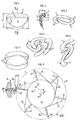
- the particle according to the present invention is characterized in that it has the shape of a substantially oval saucer of which only one side corresponding to the largest dimension is curved towards the center of the concave surface.
- it has an internal structure formed by closed cells.
- the shape of the particle according to the invention strongly resembles that of the upper part of the pavilion of the human ear, whose scientific name is helix.
- the particles according to the invention can have a length between 30 and 40 mm, a width between 20 and 30 mm and a thickness, including the curved side, between 7 and 12 mm.
- the particles allow free flow and their small thickness allows them to slip easily in thin intervals between two objects to be packaged or between an object and the carton. In addition, their small thickness contributes to obtaining an elastic memory effect. Because the internal structure of the cells is formed of a multitude of small closed cells filled with air or gas and that the surface of the particles is constituted by closed cells in great numbers, the air or the trapped gas cannot escape outward. As a result, the particles act like inflated balloons, allowing them to withstand static or dynamic pressure constraints.
- this resistance is increased by the presence of the curved side which acts both as a reinforcement and as a leaf spring.
- the particles according to the invention completely recover their initial shape after have been subjected to pressure stress.
- the wrapped objects will remain securely wedged in their packaging, even if the latter is subjected to repeated shocks.
- the particular shape of the particles according to the invention, in particular their single curved side allows perfect self-locking of the particles together in all the positions that they can take by falling by gravity into a package, which allows ensure perfect wedging of the object (s) in their packaging.
- the particles according to the invention have a rounded edge, which prevents the production of the numerous dusts which occur with previously known particles with a thin edge.
- numerous voids are formed between the particles in service, which decreases their apparent density, the latter possibly reaching values as low as 4 kg / m3 .
- the method of manufacturing particles according to the invention is similar to the known method of the third category which has been described above insofar as, as in this known method, it consists in continuously passing a mass of expandable thermoplastic material at a predetermined temperature through at least one orifice, and periodically cutting the projecting part of said mass at its exit from the orifice in order to produce several particles.
- the method according to the invention is characterized in that it consists in bending towards the center of said orifice the part of said mass which is located near one side of the periphery of said orifice, and in cutting said mass on the opposite side of the periphery of said orifice.
- said mass is maintained at a temperature between its softening point and its melting point while it leaves said orifice.
- the device for implementing the method according to the invention may comprise, in a known manner, means for continuously passing a mass of expandable thermoplastic material heated through at least one orifice, means for regulating the temperature of said mass leaving said orifice, and a rotary cutting device disposed immediately at the exit from said orifice and comprising a drum which is provided at its periphery with at least one cutting blade and whose axis of rotation is perpendicular to the axis of said orifice .
- the device according to the invention is characterized in that said orifice has, in a manner known per se, a plane end face and perpendicular to the axis of the orifice, and in that the axis of rotation of the drum is offset from the axis of the orifice in a direction such that, in the zone of exit from the orifice, the path followed by the cutting edge of the blade forms with the planar end face of the orifice a acute angle whose apex is directed in the direction of rotation of the drum.
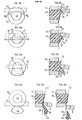
- Figures 9a to 12a and 9b to 13b are views respectively from the front in section, on a still enlarged scale, which show the action of the rotary cutting device on the expandable thermoplastic material leaving the die of the extruder used in the installation of FIG. 7.
- the particle 1 shown in Figures 1 and 2 has a convex face 2 and a concave face 3 which are connected along a closed line 4 forming a rounded edge.
- the faces 2 and 3 have a substantially smooth skin which comprises a multitude of small closed cells.
- the internal part 5 of the particle 1 is also formed by a multitude of closed cells, but of larger dimensions than those of the skin cells of the faces 2 and 3.
- Particle 1 has roughly the shape of an oval saucer, one of the two sides of which corresponds to the largest dimension is curved towards the between of the concave surface as indicated in 6.
- This curved side 6 allows particles 1 to self-lock with respect to each other in various positions as is for example illustrated in FIGS. 3 to 6.
- it gives the particles 1 a great resistance to static and dynamic stresses and a great elasticity which contributes, with the internal structure with closed cells, to allow the particles 1 to completely return to their initial shape after they have been subjected, in service, to any deformation or to any pressure stress tending to crush them.
- the particle 1 may have a length L of between approximately 30 mm and approximately 40 mm, a width 1 of between approximately 20 mm and 30 mm and a total thickness e, including the curved side 6, of between approximately 7 mm and approximately 12 mm, the actual thickness being between approximately 4 and 8 mm.
- L is approximately equal to 37 mm
- 1 is approximately equal to 26 mm
- e is approximately equal to 9 mm
- the average actual thickness being approximately equal to 5 mm.
- the installation comprises a conventional extruder or extruder heated 7 worm.
- the extruders or extruders used to extrude an expandable thermoplastic material are well known and it is therefore not considered necessary for the understanding of the invention to describe them in detail.
- the extruder 7 comprises, in a known manner, a body 8 in which turns an endless screw (not shown) which is driven by a variable speed electric motor (not shown).
- a hopper 9 containing a reserve of thermoplastic material is in communication at its narrowed lower end with the inlet or supply end of the body 8 of the extruder. As the thermoplastic material flows from the hopper 9 into the body 8 of the extruder, it is driven by the worm screw towards the opposite end of the body 8 to which a die 10 is fixed.
- the body 8 is equipped, in a known manner, with electrical heating devices (not shown), as well as with cooling devices, for example fans 11 or water cooling circuits, which, in combination with the electrical devices for heating, allow the temperature of the thermoplastic material inside the body 8 to be adjusted to the desired values along the path followed by said material from the inlet end adjacent to the hopper 9 to the die 10.
- the die 10 may comprise, in a known manner, one or more orifices of circular section.
- a rotary cutting device 12 comprising at least one cutting blade 13.
- a cutting device 12 capable of being used in the present invention is shown by way of example, to a larger extent scale, in FIG. 8.
- the cutting device 12 shown in FIG. 8 comprises a rotating cylinder or drum 14 with a horizontal axis and provided with six blades 13 regularly distributed around its periphery. Each blade 13 is fixed radially in an adjustable manner to a support 15 which is itself fixed to the drum 14 or which forms an integral part thereof.
- the axes of said orifices are arranged in a horizontal plane and are spaced transversely to the longitudinal axis of the body 8 of the extruder.
- each blade 13 must have a sufficient length in the. axial direction, that is to say in a direction parallel to the axis 16 of the drum 14, in order to be able to act simultaneously on all the ribbons or tubes of thermoplastic material leaving the orifices of the die 10.
- Each orifice of the die 10 is extended by a small cylindrical tube 17 having an end face 18 which is planar and perpendicular to the axis 19 of the tube 17.
- the drum 14 is rotated in the direction of the arrow F by means of an electric motor 20 with variable speed (shown only in FIG. 7).
- the drum 14 can be kinematically connected to the motor 20 by a suitable transmission as shown in FIG. 7 or it can be fixed directly to the shaft of the motor 20.
- the drum 14 is supported at its ends by bearings 21, which are themselves fixed on a table 22, so that the axis 16 of the drum T4 is perpendicular to the longitudinal axis 19 of the tube (s) 17 of the die 10 and offset downwards from a quantity h with respect to this axis 19 as shown in FIG. 8.
- the path T followed by the cutting edge 13a of each blade 13 forms with the flat face d end 18 of or each tube 17 an acute angle a whose apex is directed in the direction of rotation of the drum 14.
- the cutting edge 13a of each blade passes to a certain distance from the upper edge of the end of the tube 17, and it passes with a very small clearance near the lower edge of the end of the tube 17 so as to cut the mass of thermoplastic material leaving the tube 17 at the level of said lower edge as will be seen later.
- the particles of thermoplastic material cut by the rotary cutting device 12 and partially expanded fall into a hopper 23 from the lower end of which they are conveyed, for example by pneumatic transport by means of a blower 24 and a line 25 to an intermediate storage tank 26.
- a valve 27a and a line 28a connected in bypass to line 25 allow, if desired, to recover the particles directly without sending them to the intermediate storage tank 26.
- the particles are conveyed, for example by pneumatic transport by means of a blower 27 and a pipe 28 to a treatment device 29 of known type in which the particles are subjected to appropriate treatment to cause their expansion.
- the treatment device 20 may for example be an apparatus provided with a central agitator, in which the particles are brought into contact with an atmosphere of relatively hot vapor, for example water vapor.
- the expansion treatment could be carried out in any other known manner, for example by passing the particles through hot water or by subjecting them to infrared or microwave radiation.
- the particles which have been treated in the device 29 are collected in a hopper 30 from the lower end from which they are conveyed, for example by pneumatic transport by means of a blower 31 and a pipe 32, up to at a silo 33 for a few hours' maturation and drying.
- a second treatment device 34 similar to the treatment device 29, to which the particles coming from the silo 33 are conveyed by means of another blower 35 and another pipe 36, to undergo a new expansion operation before being bagged.
- the particles leaving the treatment device 34 are collected in a hopper 37 from the lower end of which they are conveyed by means of a blower 38 and a pipe 39 to a bagging station 40 where they are put in bags such as bag 41.
- the raw material used is loaded into the hopper 9 from which it flows inside the body 8 of the extruder.
- the body 8 of the extruder is heated so as to melt the raw material.
- This can for example be a polymer of styrene made expandable by the addition of known blowing agents, for example pentane or freon, in a proportion of 3 to 7% by weight of the polymer of styrene.
- blowing agents can be originally included in the raw material as found commercially, for example in the form of granules or beads intended for the manufacture of molded parts of expanded polystyrene.
- the blowing agents can be injected inside the body 8 of the extruder or mixed and diffused in any other known manner in the molten polymer.
- adjuvants such as initiating agents, agents giving the particles fire self-extinguishing properties, antistatic agents, coloring agents, wetting agents, etc. can also be added in a known manner to the raw material. These various agents can be introduced into the hopper 9 of the extruder or else mixed beforehand with the raw material in an agitator.
- a priming agent it is possible, for example, to use organic acids such as citric acid, combined with sodium bicarbonate which releases carbon dioxide.
- the advantage of adding priming agents is that they make it possible to obtain uniformity in the cell structure, on which the resistance of the particles will depend.
- the proportion of citric acid and sodium bicarbonate can be between 0.5 and 12% by weight of the styrene polymer to be extruded.
- self-extinguishing agent halogenated compounds can be used, for example, combined with other known flame retardants.
- the temperature inside the body 8 of the extruder is adjusted so that it is between 50 ° and 110 ° C. inlet end of the body 8, that is to say on the side of the hopper 9, of approximately 150 ° C. in the middle of the body 8 and finally of approximately 80 ° C. to 150 ° C. at the end opposite of the body 8 near the die 10, so as to obtain an appropriate viscosity of the styrene polymer when it passes through the orifice of the die 10.
- the temperature at said opposite end of the body 8 is adjusted in such a way that the thermoplastic material containing the swelling agent is in the plastic state, that is to say at a temperature between its softening point and its melting point, when it leaves the orifice (s) of the die 10.
- the temperature thereof at the outlet of the die 10 can be understood between 80 ° C and 120 ° C, preferably between 85 ° C and 100 ° C.
- the mass of expandable polystyrene in the plastic state leaving the die 10 is cut by the blades 13 of the rotary cutting device 12 in the following manner.
- Each blade 13, when it arrives in the position shown in FIG. 8 strikes the upper part 42 of the mass of expandable polystyrene 43 in the plastic state which leaves the tube 17 and which is located near the upper edge of the tube 17.
- the pressure thus applied by the blade 13 to the part 42 of the material 43 deforms or widens the latter in the directions indicated by the two opposite arrows H i and H 2 (FIG. 9a) and simultaneously begins to fold or bend the part 42 downwards as shown at 44 in FIG. 9b.
- the blade 13 continues to widen the mass of material 43 as shown at 45 in FIG.
- FIG. 10a shows the next phase in which the folding movement of the part 47 is further accentuated and the blade 13 approaches the lower edge of the end of the tube 17.
- Figures 12a and 12b show the chip of polystyrene 48 with its curved part 49 when it is cut from the mass of material 43 by a shearing effect by the blade 13 in cooperation with the lower edge of the end of the tube 17.
- FIG. 13b shows the polystyrene chip 48 which has just been cut and which is propelled by the blade 13 towards the hopper 23 (not shown in FIG. 13b).
- the part 44, 46, 47, 49 of the mass of polystyrene 43 which is bent during the movement of the blade 13 and which will constitute the curved side 6 of the particle 1 (FIGS. 1 and 2) sticks or is slightly welded to the end face 50 of the mass of polystyrene 43, but this does not matter because the curved part 49 will peel off during the expansion treatment to which the chips 48 are subjected subsequently.
- the blades 13 cut out the mass of polystyrene 43 which leaves the tube 17 before a significant expansion cannot occur.
- the chips 48 are partly expanded under the action of the gases which they contain and which expand under the effect of the internal residual temperature of the chips which are still relatively soft and which are now in the air at atmospheric pressure.
- the gas diffuses into the material of the relatively soft chips which, by cooling in contact with the air, traps the gas by giving an internal structure with closed cells.
- the chips have an apparent density of around 25 to 35 kg / m 3 .
- the chips 48, partially expanded, are conveyed by the blower 24 and the conduit 25 to the reservoir 26 from where they are conveyed by the blower 27 and the conduit 28 to the treatment device 29 in which they are brought into contact with steam saturated water at atmospheric pressure for a few minutes.
- the calories provided by the water vapor soften the polystyrene and again expand the gas contained in the particles, which causes them to expand.
- the curved part 49 of the shavings 48 peels off and its camber increases even more so as to form the curved side 6 of the particle 1 represented in FIGS. 1 and 2.
- the expanded particles are conveyed by the blower 31 and the pipe 32 into the silo 33 for maturation for a few hours and drying.
- the speed of rotation of the drum 14 was set to about 2200 rpm and the speed of rotation of the worm of the extruder 7 was set to about 105 rpm.
- the axis 16 of the drum was offset from the axis 19 of the tube 17 by an amount h equal to 9 mm.
- the particles obtained after the two-stage expansion treatment described above had the shape shown in FIGS. 1 and 2, with a length L approximately equal to 37 mm, equal to 9 mm and an apparent density of 5 kg / m 3 approximately.
- the dimensions of the particles depend on the internal diameter d of the tube 17, on the speed of rotation of the drum 14 and on the speed of extrusion, the latter itself depending on the speed of rotation of the worm of the extruder, the viscosity of the polymer and of the internal diameter d of the tube 17.
- the diameter d of the tube 17 can be between 3 and 8 mm without the shape of the particles changing.
- the number of blades 13 is not necessarily equal to 10.
- the cutting device 12 could be arranged immediately at the outlet of another calibration orifice located downstream of the die 10.
- arrangements should be made to prevent the expandable thermoplastic material from expanding between the die 10 and the other calibration orifice and to maintain said material at a temperature such that it is in the plastic state at the outlet of said calibration orifice, that is to say at a temperature between its softening point and its melting point.
- the axis of rotation of the cutting device 12 must be offset with respect to the axis of the calibration orifice in the same manner as with respect to the axis of the outlet orifice of the die 10.
- the particles can be expanded by any other known means.
Landscapes
- Engineering & Computer Science (AREA)
- Mechanical Engineering (AREA)
- Processing And Handling Of Plastics And Other Materials For Molding In General (AREA)
- Manufacture Of Porous Articles, And Recovery And Treatment Of Waste Products (AREA)
Applications Claiming Priority (2)
| Application Number | Priority Date | Filing Date | Title |
|---|---|---|---|
| FR8011497A FR2482930A1 (fr) | 1980-05-23 | 1980-05-23 | Particule de remplissage en mousse de matiere thermoplastique, procede et dispositif pour sa fabrication |
| FR8011497 | 1980-05-23 |
Publications (2)
| Publication Number | Publication Date |
|---|---|
| EP0041431A1 EP0041431A1 (fr) | 1981-12-09 |
| EP0041431B1 true EP0041431B1 (fr) | 1983-11-30 |
Family
ID=9242260
Family Applications (1)
| Application Number | Title | Priority Date | Filing Date |
|---|---|---|---|
| EP81400800A Expired EP0041431B1 (fr) | 1980-05-23 | 1981-05-21 | Particule de remplissage en mousse de matière thermoplastique, procédé et dispositif pour sa fabrication |
Country Status (3)
| Country | Link |
|---|---|
| EP (1) | EP0041431B1 (OSRAM) |
| DE (1) | DE3161542D1 (OSRAM) |
| FR (1) | FR2482930A1 (OSRAM) |
Families Citing this family (2)
| Publication number | Priority date | Publication date | Assignee | Title |
|---|---|---|---|---|
| DE3435440A1 (de) * | 1983-12-10 | 1985-06-20 | Hoechst Ag, 6230 Frankfurt | Aufschaeumbares kunststoffgranulat und daraus hergestelltes packmaterial |
| JPH06503226A (ja) * | 1990-09-24 | 1994-04-14 | テンダパック テクノロジーズ プロプライエタリー リミテッド | 食品処理機械および処理方法 |
Citations (3)
| Publication number | Priority date | Publication date | Assignee | Title |
|---|---|---|---|---|
| GB687398A (en) | 1951-08-29 | 1953-02-11 | Dow Chemical Co | Improvements in or relating to methods of making free-flowing cellular pellets of thermoplastic resins |
| DE2359064A1 (de) | 1972-11-28 | 1974-06-06 | Alta Ind | Verfahren und vorrichtung zur herstellung loser, zelliger fuellmaterialkoerper |
| US3961000A (en) | 1972-11-28 | 1976-06-01 | Altainer Incorporated | Method of manufacturing a nesting or interlocking loose-fill cellular packing material |
Family Cites Families (8)
| Publication number | Priority date | Publication date | Assignee | Title |
|---|---|---|---|---|
| BE621903A (OSRAM) * | 1960-11-15 | |||
| US3188264A (en) * | 1962-12-21 | 1965-06-08 | Tektronix Inc | Loose fill packing material |
| US3400037A (en) * | 1964-11-13 | 1968-09-03 | Alta Ind | Method of manufacturing cellular packing materials |
| FR2019870A1 (en) * | 1968-10-04 | 1970-07-10 | Free Flow Packaging Corp | Mass production of plastic foam packing |
| US3481455A (en) * | 1968-10-10 | 1969-12-02 | Free Flow Packaging Corp | Free-flowing packing material of low bulk density |
| FR2019270A1 (OSRAM) * | 1969-09-25 | 1970-07-03 | Zwickert Charles | |
| USRE27243E (en) * | 1970-01-12 | 1971-12-14 | Method of manufacturing cellular packing materials | |
| DE2154754C3 (de) * | 1971-11-04 | 1978-08-31 | Basf Ag, 6700 Ludwigshafen | Verfahren zur Herstellung expandierbarer Styrolpolymerisate |
-
1980
- 1980-05-23 FR FR8011497A patent/FR2482930A1/fr active Granted
-
1981
- 1981-05-21 EP EP81400800A patent/EP0041431B1/fr not_active Expired
- 1981-05-21 DE DE8181400800T patent/DE3161542D1/de not_active Expired
Patent Citations (4)
| Publication number | Priority date | Publication date | Assignee | Title |
|---|---|---|---|---|
| GB687398A (en) | 1951-08-29 | 1953-02-11 | Dow Chemical Co | Improvements in or relating to methods of making free-flowing cellular pellets of thermoplastic resins |
| DE2359064A1 (de) | 1972-11-28 | 1974-06-06 | Alta Ind | Verfahren und vorrichtung zur herstellung loser, zelliger fuellmaterialkoerper |
| FR2207796A1 (OSRAM) | 1972-11-28 | 1974-06-21 | Alta Ind | |
| US3961000A (en) | 1972-11-28 | 1976-06-01 | Altainer Incorporated | Method of manufacturing a nesting or interlocking loose-fill cellular packing material |
Also Published As
| Publication number | Publication date |
|---|---|
| FR2482930A1 (fr) | 1981-11-27 |
| FR2482930B1 (OSRAM) | 1983-07-18 |
| EP0041431A1 (fr) | 1981-12-09 |
| DE3161542D1 (en) | 1984-01-05 |
Similar Documents
| Publication | Publication Date | Title |
|---|---|---|
| BE1000954A3 (fr) | Perfectionnements a la reconstitution du tabac. | |
| EP2072219B1 (fr) | Dispositif et procédé de préparation d'un profilé d'un gel thermoplastique élastomère | |
| CH379111A (fr) | Objet de matière plastique alvéolée de faible épaisseur, procédé pour sa fabrication et dispositif pour la mise en oeuvre du procédé | |
| EP1529620A1 (fr) | Contenant en résine polyester, son procédé de fabrication et dispositif pour sa mise en oeuvre | |
| CH675048A5 (OSRAM) | ||
| FR2458380A1 (fr) | Preforme tubulaire en matiere thermoplastique et procede et equipement pour sa fabrication | |
| EP0782416A1 (fr) | Prothese mammaire | |
| CH647935A5 (fr) | Procede pour la production d'un materiau de remplissage, machine pour sa mise en oeuvre, application du procede et installation pour la production d'un boudin de filtres de cigarettes. | |
| CH639604A5 (en) | Fibre ink reservoir, particularly for marking instruments, method and apparatus for making this reservoir | |
| EP0041431B1 (fr) | Particule de remplissage en mousse de matière thermoplastique, procédé et dispositif pour sa fabrication | |
| CH434717A (fr) | Procédé de fabrication d'un tube et appareil pour la mise en oeuvre de ce procédé | |
| FR2512328A1 (fr) | Procede et dispositif pour la fabrication d'une patisserie creuse, fourree au moins partiellement sur son cote interne | |
| EP0270462B1 (fr) | Procédé et appareil pour la fabrication d'un article composite de section constante comprenant une âme et une enveloppe extérieure et article composite en résultant | |
| FR2927274A1 (fr) | Procede pour la fabrication d'une structure tridimensionnelle perforee a base de matiere plastique et dispositif pour la mise en oeuvre de ce procede | |
| FR2957018A1 (fr) | Procede et appareillage pour la fabrication d'un corps creux en matiere plastique a partir de deux feuilles | |
| EP0267900A1 (fr) | Procede et appareils d'extrusion de structures alveolaires en matiere thermoplastique et structures ainsi obtenues | |
| FR2517591A1 (fr) | Procede et dispositif pour fabriquer en continu des blocs de mousse de polymeres | |
| FR2462254A1 (fr) | Tubes et profiles biorientes en matiere thermoplastique et leur procede de fabrication | |
| FR2613911A1 (fr) | Appareil a eplucher et calibrer des endives et autres legumes analogues | |
| BE532009A (OSRAM) | ||
| EP1824663B1 (fr) | Procede de fabrication en continu d'un complexe souple et complexe souple | |
| EP4261006B1 (fr) | Tige d'étirage et de refroidissement pour la formation de récipients | |
| FR2954209A1 (fr) | Methode et appareil pour produire des bouteilles en matiere plastique | |
| FR2497814A1 (fr) | Billes creuses obtenues a partir de matieres plastiques expansibles et procede d'obtention | |
| WO2004073860A2 (fr) | Extrudeuse pour la fabrication de particules spheroïdales ou spheroïdes |
Legal Events
| Date | Code | Title | Description |
|---|---|---|---|
| PUAI | Public reference made under article 153(3) epc to a published international application that has entered the european phase |
Free format text: ORIGINAL CODE: 0009012 |
|
| AK | Designated contracting states |
Designated state(s): BE CH DE GB IT LU NL |
|
| 17P | Request for examination filed |
Effective date: 19820417 |
|
| ITF | It: translation for a ep patent filed | ||
| GRAA | (expected) grant |
Free format text: ORIGINAL CODE: 0009210 |
|
| AK | Designated contracting states |
Designated state(s): BE CH DE GB IT LI LU NL |
|
| REF | Corresponds to: |
Ref document number: 3161542 Country of ref document: DE Date of ref document: 19840105 |
|
| PGFP | Annual fee paid to national office [announced via postgrant information from national office to epo] |
Ref country code: CH Payment date: 19840424 Year of fee payment: 4 |
|
| PG25 | Lapsed in a contracting state [announced via postgrant information from national office to epo] |
Ref country code: LU Free format text: LAPSE BECAUSE OF NON-PAYMENT OF DUE FEES Effective date: 19840531 |
|
| PGFP | Annual fee paid to national office [announced via postgrant information from national office to epo] |
Ref country code: BE Payment date: 19840630 Year of fee payment: 4 |
|
| PGFP | Annual fee paid to national office [announced via postgrant information from national office to epo] |
Ref country code: DE Payment date: 19840720 Year of fee payment: 4 |
|
| PLBI | Opposition filed |
Free format text: ORIGINAL CODE: 0009260 |
|
| 26 | Opposition filed |
Opponent name: STOROPACK HANS REICHENECKER GMBH & CO Effective date: 19840829 |
|
| PGFP | Annual fee paid to national office [announced via postgrant information from national office to epo] |
Ref country code: NL Payment date: 19870531 Year of fee payment: 7 |
|
| PLBN | Opposition rejected |
Free format text: ORIGINAL CODE: 0009273 |
|
| STAA | Information on the status of an ep patent application or granted ep patent |
Free format text: STATUS: OPPOSITION REJECTED |
|
| 27O | Opposition rejected |
Effective date: 19880526 |
|
| NLR2 | Nl: decision of opposition | ||
| PG25 | Lapsed in a contracting state [announced via postgrant information from national office to epo] |
Ref country code: GB Effective date: 19890521 |
|
| PG25 | Lapsed in a contracting state [announced via postgrant information from national office to epo] |
Ref country code: LI Effective date: 19890531 Ref country code: CH Effective date: 19890531 Ref country code: BE Effective date: 19890531 |
|
| PG25 | Lapsed in a contracting state [announced via postgrant information from national office to epo] |
Ref country code: NL Effective date: 19891201 |
|
| NLV4 | Nl: lapsed or anulled due to non-payment of the annual fee | ||
| GBPC | Gb: european patent ceased through non-payment of renewal fee | ||
| REG | Reference to a national code |
Ref country code: CH Ref legal event code: PL |
|
| PG25 | Lapsed in a contracting state [announced via postgrant information from national office to epo] |
Ref country code: DE Effective date: 19900201 |
|
| APAH | Appeal reference modified |
Free format text: ORIGINAL CODE: EPIDOSCREFNO |