EP0041014B1 - Befestigungsanordnung für ein Führungsrohr eines Brennelementenbündels auf die Endplatten dieses Bündels - Google Patents
Befestigungsanordnung für ein Führungsrohr eines Brennelementenbündels auf die Endplatten dieses Bündels Download PDFInfo
- Publication number
- EP0041014B1 EP0041014B1 EP81400794A EP81400794A EP0041014B1 EP 0041014 B1 EP0041014 B1 EP 0041014B1 EP 81400794 A EP81400794 A EP 81400794A EP 81400794 A EP81400794 A EP 81400794A EP 0041014 B1 EP0041014 B1 EP 0041014B1
- Authority
- EP
- European Patent Office
- Prior art keywords
- sleeve
- ring
- rotation
- end plate
- nut
- Prior art date
- Legal status (The legal status is an assumption and is not a legal conclusion. Google has not performed a legal analysis and makes no representation as to the accuracy of the status listed.)
- Expired
Links
Images
Classifications
-
- G—PHYSICS
- G21—NUCLEAR PHYSICS; NUCLEAR ENGINEERING
- G21C—NUCLEAR REACTORS
- G21C3/00—Reactor fuel elements and their assemblies; Selection of substances for use as reactor fuel elements
- G21C3/30—Assemblies of a number of fuel elements in the form of a rigid unit
- G21C3/32—Bundles of parallel pin-, rod-, or tube-shaped fuel elements
- G21C3/33—Supporting or hanging of elements in the bundle; Means forming part of the bundle for inserting it into, or removing it from, the core; Means for coupling adjacent bundles
- G21C3/3315—Upper nozzle
-
- G—PHYSICS
- G21—NUCLEAR PHYSICS; NUCLEAR ENGINEERING
- G21C—NUCLEAR REACTORS
- G21C3/00—Reactor fuel elements and their assemblies; Selection of substances for use as reactor fuel elements
- G21C3/30—Assemblies of a number of fuel elements in the form of a rigid unit
- G21C3/32—Bundles of parallel pin-, rod-, or tube-shaped fuel elements
-
- B—PERFORMING OPERATIONS; TRANSPORTING
- B25—HAND TOOLS; PORTABLE POWER-DRIVEN TOOLS; MANIPULATORS
- B25B—TOOLS OR BENCH DEVICES NOT OTHERWISE PROVIDED FOR, FOR FASTENING, CONNECTING, DISENGAGING OR HOLDING
- B25B27/00—Hand tools, specially adapted for fitting together or separating parts or objects whether or not involving some deformation, not otherwise provided for
- B25B27/14—Hand tools, specially adapted for fitting together or separating parts or objects whether or not involving some deformation, not otherwise provided for for assembling objects other than by press fit or detaching same
- B25B27/143—Hand tools, specially adapted for fitting together or separating parts or objects whether or not involving some deformation, not otherwise provided for for assembling objects other than by press fit or detaching same for installing wire thread inserts or tubular threaded inserts
-
- G—PHYSICS
- G21—NUCLEAR PHYSICS; NUCLEAR ENGINEERING
- G21C—NUCLEAR REACTORS
- G21C3/00—Reactor fuel elements and their assemblies; Selection of substances for use as reactor fuel elements
- G21C3/30—Assemblies of a number of fuel elements in the form of a rigid unit
- G21C3/32—Bundles of parallel pin-, rod-, or tube-shaped fuel elements
- G21C3/334—Assembling, maintenance or repair of the bundles
-
- G—PHYSICS
- G21—NUCLEAR PHYSICS; NUCLEAR ENGINEERING
- G21C—NUCLEAR REACTORS
- G21C3/00—Reactor fuel elements and their assemblies; Selection of substances for use as reactor fuel elements
- G21C3/30—Assemblies of a number of fuel elements in the form of a rigid unit
- G21C3/32—Bundles of parallel pin-, rod-, or tube-shaped fuel elements
- G21C3/33—Supporting or hanging of elements in the bundle; Means forming part of the bundle for inserting it into, or removing it from, the core; Means for coupling adjacent bundles
-
- Y—GENERAL TAGGING OF NEW TECHNOLOGICAL DEVELOPMENTS; GENERAL TAGGING OF CROSS-SECTIONAL TECHNOLOGIES SPANNING OVER SEVERAL SECTIONS OF THE IPC; TECHNICAL SUBJECTS COVERED BY FORMER USPC CROSS-REFERENCE ART COLLECTIONS [XRACs] AND DIGESTS
- Y02—TECHNOLOGIES OR APPLICATIONS FOR MITIGATION OR ADAPTATION AGAINST CLIMATE CHANGE
- Y02E—REDUCTION OF GREENHOUSE GAS [GHG] EMISSIONS, RELATED TO ENERGY GENERATION, TRANSMISSION OR DISTRIBUTION
- Y02E30/00—Energy generation of nuclear origin
- Y02E30/30—Nuclear fission reactors
Definitions
- the present invention relates to fuel assemblies of nuclear reactors, for example of the type cooled by ordinary water under pressure, in which the fuel proper, distributed in a large number of unitary rods, is grouped in autonomous bundles each constituting a fuel assembly.
- Such an assembly comprises, in a known and schematic manner, two lower and upper end plates joined together by hollow guide tubes which can be used in particular for the introduction of control rods or measuring devices.
- hollow guide tubes which can be used in particular for the introduction of control rods or measuring devices.
- spacing grids which can sometimes slide freely around said guide tubes and in which are fixed, using spring systems, the unit fuel rods.
- the end plates are made of stainless steel and the guide tubes are made of a zircaloy alloy permeable to the flow of neutrons passing through them.
- European patent EP-A-0 021 912 filed on June 3, 1980 and published on January 7, 1981 relates to a method and a device for fixing such a guide tube to the end plate of a nuclear fuel assembly. which ensures a durable and solid connection using particularly simple means and easy implementation.
- the device which is the subject of this patent EP-A-0 021 912 makes a connection of the zircaloy guide tube on the end plate of the stainless steel assembly, avoiding any differential expansion between the elements. of the connection both from the point of view of diametrical deformation and of deformation in the longitudinal direction, by the very fact that the various components of the connection are mounted in abutment against each other and that welds ensure their final fixing.
- connection thus produced has given all satisfaction and functions perfectly.
- its very principle precludes any possibility of disassembly if, for example, during a maintenance operation of a fuel assembly, it is necessary to disassemble the upper end plate to replace one or more fuel rods which would have become defective.
- such an operation must necessarily be done in a radiation protection pool, that is to say through a layer of water several meters deep, the technical problems posed by the dismantling of a guide tube are relatively complex and have not received a satisfactory solution to date.
- the present invention specifically relates to a device for fixing such a guide tube in a removable manner to the end plate of this assembly, and this by means ensuring the robustness of the fixing and the total reliability of the fixing operations. and disassembly.
- the fixing device essentially comprises a nut-ring comprising two reverse pitch threads.
- the guide tube is enclosed, as in patent EP-AO 021 912, between an internal sleeve and an external ferrule.
- the upper part of the sleeve has a thread on which the nut ring is screwed and the sleeve is thus fixed by clamping between two shoulders on the upper end plate when the nut ring is screwed fully.
- this ring-nut is first screwed by its second upper thread onto the threaded end of a pole for handling the assembly from the outside above the assembly storage pool. .
- the present invention it is useful to slow down the rotation of the nut-ring and prevent, for example, that it is not being driven in the opposite direction since the end of the pole, to provide means for braking its rotation with respect to - screw of the sleeve.
- Various known means can be used for this purpose.
- these braking means are produced by a curvilinear semi-ring placed deformed, limited by a transverse slot made in the first thread of the ring-nut.
- the means for braking the rotation of the nut ring with respect to the sleeve consist of an imprint machined on the nut ring and intended to receive a corresponding deformation of the plate end.
- these means for preventing rotation of the sleeve relative to the upper end plate consist of grooves cut on the external periphery of the sleeve and cooperating with a complementary grooved housing machined to the facing surface of the upper end plate.
- these same means consist of lugs carried by the surface of a cylindrical mandrel held stationary in rotation and housed in the central recess of the pole made for this purpose of a hollow cylinder, said pins cooperating with grooves cut on the internal surface of said sleeve.
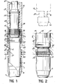
- the upper end plate 2 has two shoulders, respectively 20 at the upper part and 21 at the lower part, the shoulder 21 cooperating with the upper shoulder 6 of the sleeve 3.
- the nut-ring 12 having a first lower thread 22 and a second thread 23, the threads 22 and 23 being, according to the invention, of opposite pitch.
- a housing 24 hollowed out in the upper part of the end plate 2 allows the passage of the ring-nut 12. This still has a curved semi-ring placed deformed, limited by a transverse slot 25 intended to create a certain friction on the threads of the tapped upper part 26 of the sleeve 3 in order to slow down the rotation of the ring-nut 12 relative to this same sleeve 3.
- the second upper thread 23 of the nut-ring 12 cooperates with the threaded end piece 14 mounted at the end of the pole 27 with the aid of which, from the surface of the pool not shown, the whole device is operated .
- the ring-nut 12 also has at its upper periphery a number of recesses 17 intended to cooperate with notches 16 carried by the base of a sheath-screwdriver 15 located around the lower part of the pole 27 and movable along of the latter only in translation thanks to a keying 28 which secures the screwdriver sheath 15 in rotation with the pole 27.
- the screwdriver sheath 15 has a shoulder 29 defining a housing 30 between the wall of the pole 27 and the sheath-screwdriver 15 in which is housed a spring 31 normally intended, that is to say when the experimenter on the surface does not exert on the screwdriver sheath 15 an antagonistic action tending to compress the spring 31, to cause the notches 16 to penetrate into the recesses 17 of the nut-ring 12 and thus to make the ring-nut 12 and the pole 27 integral in rotation.
- 2 ie sleeve 3 still has a number of notches 32 located at the periphery of an annular zone of this sleeve 3 and cooperating with a complementary grooved housing 33 of the end plate 2.
- the notches of the groove 32 penetrate into the hollow parts of the complementary grooved housing 33 thus preventing any rotation of the sleeve 3 and therefore of the guide tube 1 relative to the end plate 2, during the mounting and mounting operations. disassembly of the device. This is obviously made necessary by the fact that the preceding operations taking place under the effect of rotations in one direction or another of the ring-nut 12, it is essential that the guide tube 1 is fixed in rotation relative to the end plate 2.
- the operation of the device of Figure 1 is then as follows. If you want, for example, to fix the guide tube 1 and its sleeve 3 to the upper end plate 2 using the ring 12, this is done as follows. The operator first begins, outside the protective pool, by fixing the nut ring 12 to the end of the pole 27 by screwing the second upper thread 22 onto the end piece 14 of this pole 27. To do this, the operator is obviously forced, first, to lift the sheath screwdriver 15 upwards so that the notches 16 release the external surface of the thread 23 from the end piece 14. This operation being performed, the operator releases the sheath screwdriver 15 and under the effect of the spring 31 which relaxes, the notches 16 then penetrate into the corresponding recesses 17 in the upper part of the nut-ring 12.
- the assembly thus prepared is lowered into the pool and the nut-ring 12 begins to be screwed by its first lower thread 22 along the tapped upper part 26 of the sleeve 3.
- the operator continues to rotate the pole 27 always in the same direction until that the nut-ring 12 abuts against the upper shoulder laughing 20 of the upper end plate 2.
- the operator acts again on the sheath screwdriver 15 whose spring it compresses to release the notches 16 from the recesses 17, which separates the pole 27 and its tip 14 of the ring 12.
- the second upper thread 23 of the nut-ring 12 is of opposite pitch to the first lower thread 22, the operator unscrews the end piece 14 of the nut-ring 12 while continuing to rotate in the same direction .
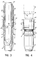
- FIG. 3 the corresponding elements of FIGS. 1 and 2 bearing the same reference numbers and in particular the sheath 15 provided with a locking pin 38 to secure in rotation the sheath 15 and the pole 27.
- the mandrel 35 is introduced and / or removed at the same time as the pole 27 and it has a centering tip 39 which allows facilitate its positioning during the introduction of this pole 27 into the device for an assembly or disassembly operation.
Landscapes
- Engineering & Computer Science (AREA)
- Physics & Mathematics (AREA)
- Plasma & Fusion (AREA)
- General Engineering & Computer Science (AREA)
- High Energy & Nuclear Physics (AREA)
- Mechanical Engineering (AREA)
- Monitoring And Testing Of Nuclear Reactors (AREA)
- Clamps And Clips (AREA)
Claims (5)
Applications Claiming Priority (2)
| Application Number | Priority Date | Filing Date | Title |
|---|---|---|---|
| FR8011695 | 1980-05-27 | ||
| FR8011695A FR2483669A2 (fr) | 1978-05-23 | 1980-05-27 | Dispositif de fixation d'un tube de guidage d'un assemblage combustible nucleaire aux plaques d'extremites dudit assemblage |
Publications (2)
| Publication Number | Publication Date |
|---|---|
| EP0041014A1 EP0041014A1 (de) | 1981-12-02 |
| EP0041014B1 true EP0041014B1 (de) | 1985-02-20 |
Family
ID=9242353
Family Applications (1)
| Application Number | Title | Priority Date | Filing Date |
|---|---|---|---|
| EP81400794A Expired EP0041014B1 (de) | 1980-05-27 | 1981-05-20 | Befestigungsanordnung für ein Führungsrohr eines Brennelementenbündels auf die Endplatten dieses Bündels |
Country Status (7)
| Country | Link |
|---|---|
| US (1) | US4416848A (de) |
| EP (1) | EP0041014B1 (de) |
| KR (1) | KR840002450B1 (de) |
| CA (1) | CA1179073A (de) |
| DE (1) | DE3169007D1 (de) |
| ES (1) | ES502494A0 (de) |
| ZA (1) | ZA813373B (de) |
Families Citing this family (30)
| Publication number | Priority date | Publication date | Assignee | Title |
|---|---|---|---|---|
| FR2518302A1 (fr) * | 1981-12-14 | 1983-06-17 | Commissariat Energie Atomique | Procede de fabrication d'un assemblage combustible de reacteur nucleaire du type a eau legere et outillage pour la mise en oeuvre du procede |
| FR2529704B1 (fr) * | 1982-07-01 | 1987-09-04 | Commissariat Energie Atomique | Dispositif de fixation demontable d'un tube guide dans la piece d'extremite d'un assemblage combustible de reacteur nucleaire |
| DE3240061A1 (de) * | 1982-10-28 | 1984-05-03 | Kraftwerk Union AG, 4330 Mülheim | Kernreaktorbrennelement |
| US4603027A (en) * | 1983-12-21 | 1986-07-29 | Westinghouse Electric Corp. | Removable top nozzle and tool for a nuclear reactor fuel assembly |
| FR2564680B1 (fr) * | 1984-05-18 | 1986-10-17 | Metanic Sa | Thermoplongeur perfectionne et enceinte sous pression en comportant application |
| US4684498A (en) * | 1985-03-29 | 1987-08-04 | Westinghouse Electric Corp. | Guide thimble captured locking tube in a reconstitutable fuel assembly |
| US4699758A (en) * | 1985-04-02 | 1987-10-13 | Westinghouse Electric Corp. | Reusable locking tube in a reconstitutable fuel assembly |
| US4818473A (en) * | 1985-05-08 | 1989-04-04 | Westinghouse Electric Corp. | Fuel bundle |
| US4668469A (en) * | 1985-06-10 | 1987-05-26 | Westinghouse Electric Corp. | Fastener locking device for attaching guide thimble to fuel assembly bottom nozzle |
| US4664874A (en) * | 1985-09-05 | 1987-05-12 | Westinghouse Electric Corp. | Reusable locking tube insertion and removal fixture and method in a reconstitutable fuel assembly |
| US4687631A (en) * | 1985-09-12 | 1987-08-18 | Westinghouse Electric Corp. | Top nozzle mounted reusable fastener device in a reconstitutable nuclear fuel assembly |
| US4707331A (en) * | 1985-11-14 | 1987-11-17 | Westinghouse Electric Corp. | Top end support for water displacement rod guides of pressurized water reactor |
| US4748733A (en) * | 1986-08-29 | 1988-06-07 | Westinghouse Electric Corp. | Removal of old split-pin assemblies from guide tubes and replacement by new split-pin assemblies |
| US4764340A (en) * | 1986-10-31 | 1988-08-16 | Westinghouse Electric Corp. | Fuel assembly stress relieving fastener |
| US4857264A (en) * | 1986-11-03 | 1989-08-15 | Westinghouse Electric Corp. | Frictionally loaded top end supports for cantilever-mounted rod guides of a pressurized water reactor |
| US4937039A (en) * | 1989-01-17 | 1990-06-26 | Westinghouse Electric Corp. | Four pin mounting system for nuclear reactor control rod guide tubes |
| DE4123727A1 (de) * | 1991-07-17 | 1993-01-21 | Siemens Ag | Kernreaktorbrennelement |
| DE4125084A1 (de) * | 1991-07-29 | 1993-02-04 | Siemens Ag | Kernreaktorbrennelement |
| US5207980A (en) * | 1991-10-27 | 1993-05-04 | Westinghouse Electric Corp. | Top nozzle-mounted replacement guide pin assemblies |
| US5461647A (en) * | 1994-08-31 | 1995-10-24 | B&W Fuel Company | Drive tool for upper end fitting locking arrangement |
| ES2102907T3 (es) * | 1994-08-31 | 1997-08-01 | B & W Fuel Co | Conjunto de enclavamiento reutilizable para boquilla superior de una junta de combustible nuclear. |
| KR100330357B1 (ko) * | 1999-08-17 | 2002-04-01 | 장인순 | 방사선원 어셈블리 |
| US6769262B1 (en) | 2003-02-13 | 2004-08-03 | Babcock & Wilcox Canada Ltd. | Chilling sleeve for expansion-fitting hollow cylinders |
| US8318423B2 (en) | 2004-07-06 | 2012-11-27 | Focus Diagnostics, Inc. | Methods and compositions for detecting rhinoviruses |
| KR100800095B1 (ko) * | 2006-08-14 | 2008-02-01 | 한전원자력연료 주식회사 | 핵연료집합체의 안내관 및 계측관과 지지격자체의 기계적결합을 위한 2단 슬리브 및 조임쇠로 이루어진 체결수단 |
| FR2938204B1 (fr) * | 2008-11-07 | 2011-01-07 | Areva Np | Dispositif et procede de manipulation sous eau et a distance d'une vis telle qu'une vis de fixation des elements d'un tube-guide des equipements internes superieurs d'un reacteur nucleaire |
| KR101959004B1 (ko) * | 2018-05-09 | 2019-03-15 | 한전원자력연료 주식회사 | 4발 동시 체결형 사용후 핵연료 취급 안전성 보완기구 |
| CN109176409B (zh) * | 2018-11-20 | 2021-01-22 | 中车长春轨道客车股份有限公司 | 螺纹套安装旋压装置 |
| KR102027369B1 (ko) * | 2019-01-16 | 2019-11-04 | 한전원자력연료 주식회사 | 사용후 핵연료 집합체의 취급용 고정 장치의 설치 방법 |
| FR3101997B1 (fr) * | 2019-10-14 | 2023-02-10 | Framatome Sa | Dispositif de maintenance d’un assemblage de combustible, ensemble et procédé de maintenance associés |
Family Cites Families (11)
| Publication number | Priority date | Publication date | Assignee | Title |
|---|---|---|---|---|
| GB839782A (en) * | 1957-06-24 | 1960-06-29 | Atomic Energy Authority Uk | Improvements in or relating to joints between tubes of dissimilar materials |
| BE759403A (fr) * | 1969-11-26 | 1971-04-30 | Babcock & Wilcox Co | Assemblage combustible perfectionne pour un reacteur nucleaire |
| US4030975A (en) * | 1973-06-25 | 1977-06-21 | Combustion Engineering, Inc. | Fuel assembly for a nuclear reactor |
| US3971575A (en) * | 1974-11-29 | 1976-07-27 | Combustion Engineering, Inc. | Releasable locking device |
| US4166313A (en) * | 1975-08-01 | 1979-09-04 | The Babcock & Wilcox Company | Nuclear fuel element nut retainer cup tool |
| US4036692A (en) * | 1975-08-01 | 1977-07-19 | The Babcock & Wilcox Company | Nuclear fuel element nut retainer cup |
| US4219386A (en) * | 1977-06-10 | 1980-08-26 | Exxon Nuclear Company, Inc. | PWR Integral tie plate and locking mechanism |
| FR2420826A1 (fr) * | 1978-03-22 | 1979-10-19 | Commissariat Energie Atomique | Assemblage combustible montable et demontable a distance pour reacteur nucleaire et outils correspondants |
| US4284475A (en) * | 1979-01-26 | 1981-08-18 | Combustion Engineering, Inc. | Wear sleeve for control rod guide tube |
| FR2493024B1 (fr) * | 1980-10-29 | 1986-08-29 | Franco Belge Combustibles | Dispositif de liaison demontable pour la realisation des assemblages combustibles des reacteurs nucleaires a eau legere |
| US4366116A (en) * | 1981-03-05 | 1982-12-28 | The United States Of America As Represented By The United States Department Of Energy | Nuclear reactor fuel assembly duct-tube-to-handling-socket attachment system |
-
1981
- 1981-05-20 US US06/265,601 patent/US4416848A/en not_active Expired - Fee Related
- 1981-05-20 ZA ZA00813373A patent/ZA813373B/xx unknown
- 1981-05-20 DE DE8181400794T patent/DE3169007D1/de not_active Expired
- 1981-05-20 EP EP81400794A patent/EP0041014B1/de not_active Expired
- 1981-05-25 KR KR1019810001822A patent/KR840002450B1/ko active
- 1981-05-26 ES ES502494A patent/ES502494A0/es active Granted
- 1981-05-26 CA CA000378361A patent/CA1179073A/en not_active Expired
Also Published As
| Publication number | Publication date |
|---|---|
| KR830006771A (ko) | 1983-10-06 |
| EP0041014A1 (de) | 1981-12-02 |
| CA1179073A (en) | 1984-12-04 |
| KR840002450B1 (ko) | 1984-12-28 |
| ES8404094A1 (es) | 1984-04-01 |
| US4416848A (en) | 1983-11-22 |
| ZA813373B (en) | 1982-06-30 |
| DE3169007D1 (en) | 1985-03-28 |
| ES502494A0 (es) | 1984-04-01 |
Similar Documents
| Publication | Publication Date | Title |
|---|---|---|
| EP0041014B1 (de) | Befestigungsanordnung für ein Führungsrohr eines Brennelementenbündels auf die Endplatten dieses Bündels | |
| EP0098774B1 (de) | Demontierbare Einrichtung zur Fixierung eines Führungsrohres in der Endplatte eines Kernreaktorbrennelementbündels | |
| EP0007251B1 (de) | Auf Abstand montierbares und demontierbares Kernreaktorbrennelement und dafür geeignete Werkzeuge | |
| WO2002017995A1 (fr) | Dispositif de protection pour seringue, en particulier pour une seringue servant a l'injection de produit(s) radioactif(s) | |
| FR2485754A1 (fr) | Connecteur de fibres optiques | |
| EP0418160A1 (de) | Vorrichtung zur dichten Befestigung eines austauschbaren Teiles an einem Zellenflansch und Werkzeug zur Montage einer solchen Vorrichtung | |
| BE1004592A4 (fr) | Procede de chemisage de tube d'instrumentation d'assemblage combustible nucleaire et assemblage a tube chemise. | |
| EP0021912B1 (de) | Verfahren und Vorrichtung zur Befestigung eines im Kernbrennelementbündel anwesenden Führungsrohres mit den Endplatten dieses Bündels | |
| EP0014614A1 (de) | Demontierbare Vorrichtung für die Einfügung eines Gerätes zwischen zwei Rohren | |
| EP0321317B1 (de) | Vorrichtung zum Schweissen eines Endes eines im Inneren einer Bohrung befestigten Rohrstückes, die sich zur Vorderseite einer Platte hin öffnet, wie bei einem Siederohrdampferzeuger | |
| EP0219412B1 (de) | Vorrichtung zum Verriegeln eines Führungsringes auf einer mit einer Öffnung versehenen Platte und Anwendung für ein Führungsrohr eines Kernreaktors | |
| FR2512255A1 (fr) | Dispositif de jonction demontable et utilisation de ce dispositif pour assemblage combustible pour reacteur nucleaire | |
| CA1311350C (fr) | Procede et dispositif d'extraction d'un troncon de tube d'echangeur dechaleur | |
| EP0185568B1 (de) | Bajonettverbindung für Handhabungsgeräte mit einer Sicherung gegen unversehenes Lösen | |
| EP0349379B1 (de) | Regelspinne mit demortierbaren Stäben für ein Kernbrennstabbündel | |
| FR2483669A2 (fr) | Dispositif de fixation d'un tube de guidage d'un assemblage combustible nucleaire aux plaques d'extremites dudit assemblage | |
| EP0427628B1 (de) | Dosisleistungsmessvorrichtung in einem radioaktive Abfälle enthaltenden Transportbehälter | |
| EP0428433B1 (de) | Vorrichtung zum Fixieren der Steuerstabsführungsplatte im Kernreaktordruckgefäss | |
| BE1005401A0 (fr) | Dispositif de broche de support destine a des tubes de guidage de barre de commande d'un reacteur nucleaire. | |
| FR2693310A1 (fr) | Procédé d'utilisation d'un doigt de gant d'un réacteur nucléaire à eau sous pression et dispositif de réglage de la position axiale du doigt de gant. | |
| EP0118355A1 (de) | Brennstoffbündel für einen Kernreaktor | |
| BE1005841A3 (fr) | Coupleur de securite pour robinet de recipient de fluide sous pression. | |
| EP1037215A1 (de) | Vorrichtung zum Anschliessen an ein Führungsrohr des Deckels eines Druckwasserkernreaktordruckbehälters | |
| FR2558637A1 (fr) | Dispositif pour la mise en place d'une source radioactive dans un logement cylindrique et procede de transfert de cette source dans un chateau de transfert | |
| FR2628636A1 (fr) | Appareil pousse-seringue dote d'un dispositif perfectionne pour le maintien de la collerette terminale du piston d'une seringue sur le sabot-poussoir de cet appareil |
Legal Events
| Date | Code | Title | Description |
|---|---|---|---|
| PUAI | Public reference made under article 153(3) epc to a published international application that has entered the european phase |
Free format text: ORIGINAL CODE: 0009012 |
|
| AK | Designated contracting states |
Designated state(s): BE DE GB IT NL SE |
|
| 17P | Request for examination filed |
Effective date: 19820507 |
|
| ITF | It: translation for a ep patent filed |
Owner name: JACOBACCI & PERANI S.P.A. |
|
| GRAA | (expected) grant |
Free format text: ORIGINAL CODE: 0009210 |
|
| AK | Designated contracting states |
Designated state(s): BE DE GB IT NL SE |
|
| REF | Corresponds to: |
Ref document number: 3169007 Country of ref document: DE Date of ref document: 19850328 |
|
| PLBE | No opposition filed within time limit |
Free format text: ORIGINAL CODE: 0009261 |
|
| STAA | Information on the status of an ep patent application or granted ep patent |
Free format text: STATUS: NO OPPOSITION FILED WITHIN TIME LIMIT |
|
| 26N | No opposition filed | ||
| PGFP | Annual fee paid to national office [announced via postgrant information from national office to epo] |
Ref country code: SE Payment date: 19890425 Year of fee payment: 9 |
|
| PGFP | Annual fee paid to national office [announced via postgrant information from national office to epo] |
Ref country code: DE Payment date: 19890429 Year of fee payment: 9 |
|
| PGFP | Annual fee paid to national office [announced via postgrant information from national office to epo] |
Ref country code: BE Payment date: 19890502 Year of fee payment: 9 |
|
| ITTA | It: last paid annual fee | ||
| PGFP | Annual fee paid to national office [announced via postgrant information from national office to epo] |
Ref country code: NL Payment date: 19890531 Year of fee payment: 9 Ref country code: GB Payment date: 19890531 Year of fee payment: 9 |
|
| PG25 | Lapsed in a contracting state [announced via postgrant information from national office to epo] |
Ref country code: GB Effective date: 19900520 |
|
| PG25 | Lapsed in a contracting state [announced via postgrant information from national office to epo] |
Ref country code: SE Effective date: 19900521 |
|
| PG25 | Lapsed in a contracting state [announced via postgrant information from national office to epo] |
Ref country code: BE Effective date: 19900531 |
|
| BERE | Be: lapsed |
Owner name: COMMISSARIAT A L'ENERGIE ATOMIQUE ETABLISSEMENT D Effective date: 19900531 |
|
| PG25 | Lapsed in a contracting state [announced via postgrant information from national office to epo] |
Ref country code: NL Effective date: 19901201 |
|
| GBPC | Gb: european patent ceased through non-payment of renewal fee | ||
| NLV4 | Nl: lapsed or anulled due to non-payment of the annual fee | ||
| PG25 | Lapsed in a contracting state [announced via postgrant information from national office to epo] |
Ref country code: DE Effective date: 19910201 |
|
| EUG | Se: european patent has lapsed |
Ref document number: 81400794.4 Effective date: 19910115 |