EP0040155A1 - Perfectionnements aux détecteurs de proximité statiques - Google Patents
Perfectionnements aux détecteurs de proximité statiques Download PDFInfo
- Publication number
- EP0040155A1 EP0040155A1 EP81400747A EP81400747A EP0040155A1 EP 0040155 A1 EP0040155 A1 EP 0040155A1 EP 81400747 A EP81400747 A EP 81400747A EP 81400747 A EP81400747 A EP 81400747A EP 0040155 A1 EP0040155 A1 EP 0040155A1
- Authority
- EP
- European Patent Office
- Prior art keywords
- switch
- transistor
- receiver
- detector
- circuit
- Prior art date
- Legal status (The legal status is an assumption and is not a legal conclusion. Google has not performed a legal analysis and makes no representation as to the accuracy of the status listed.)
- Withdrawn
Links
Images
Classifications
-
- H—ELECTRICITY
- H03—ELECTRONIC CIRCUITRY
- H03K—PULSE TECHNIQUE
- H03K17/00—Electronic switching or gating, i.e. not by contact-making and –breaking
- H03K17/94—Electronic switching or gating, i.e. not by contact-making and –breaking characterised by the way in which the control signals are generated
- H03K17/945—Proximity switches
- H03K17/95—Proximity switches using a magnetic detector
- H03K17/952—Proximity switches using a magnetic detector using inductive coils
- H03K17/9537—Proximity switches using a magnetic detector using inductive coils in a resonant circuit
- H03K17/9542—Proximity switches using a magnetic detector using inductive coils in a resonant circuit forming part of an oscillator
- H03K17/9547—Proximity switches using a magnetic detector using inductive coils in a resonant circuit forming part of an oscillator with variable amplitude
-
- H—ELECTRICITY
- H03—ELECTRONIC CIRCUITRY
- H03K—PULSE TECHNIQUE
- H03K17/00—Electronic switching or gating, i.e. not by contact-making and –breaking
- H03K17/94—Electronic switching or gating, i.e. not by contact-making and –breaking characterised by the way in which the control signals are generated
- H03K17/945—Proximity switches
Definitions
- the present invention relates to a static proximity detector, in particular for metal parts, comprising containing an envelope / a first electronic circuit arranged to generate a magnetic field and detect the presence in the field of an object, and a second electronic circuit, connected on the first, to control an electric receiver indicating the presence of the object in the field.
- the detection circuit generally comprises an electromagnetic sensor element - an oscillating circuit whose coil is wound on an open magnetic core -, whose oscillatory regime is strongly disturbed by the introduction of a metallic part into its radiation field.
- the binary signal from the detection circuit thus disturbed is applied to a use circuit intended to control the electrical supply of a receiver.
- This circuit of use generally comprises at least one transistor whose normal state of conduction, or blocking, is determined by the state of the signal resulting from the detection circuit, which depends on the presence, or not, of a part in the sensor field.
- the present invention aims to remedy this drawback and to provide the user with the ability to perform if necessary, thanks to a very simple action exerted on site at the time of commissioning, the transformation for example from a "closing" detector model to an "opening" model.
- the present invention relates to a static proximity detector, in particular for metal parts, comprising an envelope containing a first electronic circuit arranged to generate a magnetic field and detect the presence in the field of an object, and a second electronic circuit, connected to the first, for controlling an electrical receiver indicating the presence of the object in the field, characterized in that the second control circuit of the indication receiver comprises a first switch, connected to the output of the first detection circuit, a second switch, means connected between the output of the detection circuit and the second switch, so that the two switches are one open and the other closed, a third switch, normally in the same state as the first switch, and connected between the first switch and the receiver, means arranged to open the third switch, means arranged to connect the second switch and the receiver, and means arranged to simultaneously destroy the opening means and the connection means.
- the second control circuit of the indication receiver comprises a first switch, connected to the output of the first detection circuit, a second switch, means connected between the output of the detection circuit and the second switch, so that the two switches are one open and the other closed
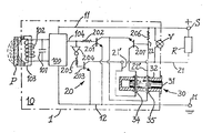
- the device shown in the figure is a proximity detector of the inductive type, the assembly 10 of the technological components of which is enclosed in an envelope 1, which is filled, for example, with polymerizable insulating resin after final assembly.
- the assembly 10 of the detector device comprises a detection circuit 100, essentially constituted by an oscillator, a sensor circuit, to which the detection circuit is adapted, and which comprises, in parallel, a capacitor 101 and a coil 102 wound on a core open magnetic 103, formed for example from a pot of soft ferrite.
- the electrical energy necessary for the maintenance of the oscillator of the detection cricuit 100 is supplied by a power source S with DC voltage, through lines 11 and 12 respectively connected to the source 5 and to the ground M.
- the impedance of the oscillating system is modified to a point such as the oscillation, maintained in the absence of part P, abruptly ceases by excess charge and a signal, in the form of a DC voltage, appears simultaneously on the output 104 of the detection circuit 100 to be applied to the next stage of the detector 10, consisting of a use or control circuit, 20.
- This circuit 20 is organized to allow, depending on the presence or absence of the part P in the oscillating field of the detection circuit 100, the remote control of an electric receiver R, connected to the source 5 and to the use circuit 20 by a line 21.
- a light indicator V is preferably mounted on the casing 3 of the detector 10 and connected between lines 11 and 21, to allow remote viewing of the supply state of the receiver R.
- the use circuit 20 comprises a first transistor 201, as a first switch, the base of which is connected, via a resistor 202, to the output 104 of the detection circuit 100, as well as a second transistor 203, as a second switch, the base of which is also connected to the output 104, but via an inverter element 204 in series with a resistor 205.
- the emitters of the two transistors are both connected to earth M via line 12.
- collectors of the transistors 201 and 203 are both connected to the power source 5 respectively through a resistor 206 and the receiver R, by means of intermediate connection lines 22 'and 21', respectively, whose particular role and arrangement will be explained below.
- the use circuit 20 comprises a third transistor 207, as a third switch, of the same type as the transistors 201 and 203, the base and the collector of which are respectively connected to the source 5, by a line 22, through the resistor 206, and to receiver R, via line 21, the emitter of transistor 207 being connected to the collector of transistor 201, and to its own base by line 22 ', which therefore isolates this transistor 207.
- This third switch is therefore connected between the first switch 201 and the receiver R and should normally be in the same state as the first switch 201.
- the detector 10 is of the so-called "closing" type corresponding to a supply to the receiver R when the part P is present in the field of the detection circuit 100.
- the transistor 203 is then blocked, the transistor 201 is, for its part, but like the transistor 207, in series with transistor 201 remains blocked due to its neutralization by the link, by line 22 ', between its base and its emitter, that is to say that this third switch 207, although the first 201 is closed, remains opened by line 22 ', the receiver R is no longer supplied and the indicator V goes out.
- the detector 10 is transformed into a type called "opening" corresponding to a stop of the supply to the receiver R when the part P is present in the field of the detection cricuit 100.
- transistor 201 is therefore always off, but transistor 203, although in the on state, is rendered inoperative due to the interruption of the connection line 21 '.
- the cutting device 30 for lines 21 ′ and 22 ′ advantageously and preferably comprises a rod 31 sliding just and with friction in a tube 32 extending over its entire length inside the envelope 1 of the detector, and whose end accessible from the outside, possibly closed by a removable cover, opens at one of the outer walls of this envelope 1.
- the assembly 30, formed by the tube 32 and the rod 31, is made of insulating material, rigid or flexible, and compar- te two separate holes 34 and 35 crossing it diametrically right through to allow, at the time of the final wiring of the detector, the threading of lines 21 'and 22' whose conductive core is normally provided in relatively soft metal, as for example in enamelled copper wire for winding.
Landscapes
- Switches That Are Operated By Magnetic Or Electric Fields (AREA)
- Geophysics And Detection Of Objects (AREA)
- Electronic Switches (AREA)
Applications Claiming Priority (2)
| Application Number | Priority Date | Filing Date | Title |
|---|---|---|---|
| FR8010689A FR2482313A1 (fr) | 1980-05-12 | 1980-05-12 | Perfectionnements aux detecteurs de proximite statiques |
| FR8010689 | 1980-05-12 |
Publications (1)
| Publication Number | Publication Date |
|---|---|
| EP0040155A1 true EP0040155A1 (fr) | 1981-11-18 |
Family
ID=9241917
Family Applications (1)
| Application Number | Title | Priority Date | Filing Date |
|---|---|---|---|
| EP81400747A Withdrawn EP0040155A1 (fr) | 1980-05-12 | 1981-05-11 | Perfectionnements aux détecteurs de proximité statiques |
Country Status (2)
| Country | Link |
|---|---|
| EP (1) | EP0040155A1 (ref) |
| FR (1) | FR2482313A1 (ref) |
Cited By (1)
| Publication number | Priority date | Publication date | Assignee | Title |
|---|---|---|---|---|
| FR2606163A1 (fr) * | 1986-10-29 | 1988-05-06 | Baumer Electric Ag | Procede de detection sans contact de corps parcourus par des courants de foucault, en particulier d'objets metalliques, ainsi que les detecteurs qui s'appuient sur le procede |
Citations (3)
| Publication number | Priority date | Publication date | Assignee | Title |
|---|---|---|---|---|
| FR2010855A1 (ref) * | 1968-06-14 | 1970-02-20 | Bosch | |
| CH488279A (de) * | 1969-07-25 | 1970-03-31 | Landis & Gyr Ag | Induktive Annäherungsschalteinrichtung, insbesondere zur Verwendung als Endschalter |
| FR2302502A1 (fr) * | 1975-02-27 | 1976-09-24 | Telemecanique Electrique | Detecteur de proximite a courant continu du type a deux fils a fonctions travail et/ou repos |
-
1980
- 1980-05-12 FR FR8010689A patent/FR2482313A1/fr active Granted
-
1981
- 1981-05-11 EP EP81400747A patent/EP0040155A1/fr not_active Withdrawn
Patent Citations (4)
| Publication number | Priority date | Publication date | Assignee | Title |
|---|---|---|---|---|
| FR2010855A1 (ref) * | 1968-06-14 | 1970-02-20 | Bosch | |
| CH488278A (de) * | 1968-06-14 | 1970-03-31 | Bosch Gmbh Robert | Elektronische Annäherungsschalteinrichtung |
| CH488279A (de) * | 1969-07-25 | 1970-03-31 | Landis & Gyr Ag | Induktive Annäherungsschalteinrichtung, insbesondere zur Verwendung als Endschalter |
| FR2302502A1 (fr) * | 1975-02-27 | 1976-09-24 | Telemecanique Electrique | Detecteur de proximite a courant continu du type a deux fils a fonctions travail et/ou repos |
Non-Patent Citations (2)
| Title |
|---|
| Components Report, Vol. 9, No. 5, Decembre 1974, Siemens A.G. Munich (DE) A. HAUENSTEIN et al.: "Integrated Threshold Switch TCA 105" pages 126-129 * figures 1,12; pages 126,129 * * |
| Radio Fernsehen Elektronik, Vol. 26, No. 12, Juin 1977 Berlin (DD) BUTTGEREIT: "Die Integrierte Initiatorschaltung A 301 D" pages 403-406 * figures 1,2; page 403 * * |
Cited By (1)
| Publication number | Priority date | Publication date | Assignee | Title |
|---|---|---|---|---|
| FR2606163A1 (fr) * | 1986-10-29 | 1988-05-06 | Baumer Electric Ag | Procede de detection sans contact de corps parcourus par des courants de foucault, en particulier d'objets metalliques, ainsi que les detecteurs qui s'appuient sur le procede |
Also Published As
| Publication number | Publication date |
|---|---|
| FR2482313A1 (fr) | 1981-11-13 |
| FR2482313B1 (ref) | 1984-08-10 |
Similar Documents
| Publication | Publication Date | Title |
|---|---|---|
| FR2487976A1 (fr) | Dispositif pour detecter le niveau de remplissage dans un recipient | |
| FR2554633A1 (fr) | Dispositif de commande d'alimentation intermittente d'appareils electriques notamment d'une chambre d'hotel | |
| FR2563352A1 (fr) | Appareil d'alarme avec commande a distance du mode de fonctionnement | |
| EP0040155A1 (fr) | Perfectionnements aux détecteurs de proximité statiques | |
| FR2468069A1 (fr) | Appareil permettant de detecter l'existence d'une fuite dans un circuit parcouru de maniere discontinue par un fluide | |
| EP0440525B1 (fr) | Dispositif de commande de l'alimentation électrique de plusieurs appareils électriques à partir d'une source de courant continu | |
| CA1299623C (fr) | Element electrique isole chauffant a dispositif de securite detectant la defaillance de l'isolement electrique | |
| FR1465008A (fr) | Dispositif contacteur photosensible | |
| FR2743453A3 (fr) | Dispositif de securite pour appareil electromenager | |
| FR2697397A1 (fr) | Dispositif d'adaptation active d'impédance entre un transducteur ultrasonore et le générateur de signaux impulsionnels destinés à ce tranducteur. | |
| FR2635212A1 (fr) | Dispositif de protection d'un appareil electrique contre le vol | |
| CH680960A5 (en) | Wall mounted power outlet socket - includes reed switch controlling live socket supply activated by magnet in plug | |
| EP0212993B1 (fr) | Perfectionnement aux appareils de télécommande électriques | |
| FR2471433A3 (fr) | Dispositif de controle de l'admission d'eau pour machines de lavage raccordees au reseau de distribution | |
| FR2639107A1 (fr) | Procede et dispositif pour detecter l'etat d'une vanne | |
| EP0433514A1 (fr) | Agencement d'entrée-sortie testable pour charge découplÀ©é par transformateur | |
| EP0120874A1 (fr) | Dispostif d'interruption de courant electrique. | |
| CH504743A (fr) | Dispositif de surveillance des conditions d'enneigement | |
| FR2621802A1 (fr) | Dispositif de detection et de telesignalisation d'arrivee du courrier et/ou autres plis ou paquets | |
| EP0479694A1 (fr) | Dispositif de distribution de courant pour tableau de distribution d'énergie électrique | |
| JPH0738000B2 (ja) | 活線電流測定器 | |
| FR2696599A1 (fr) | Contacts auxiliaires pour appareil électrique. | |
| FR2480999A1 (fr) | Perfectionnements aux ensembles de cartouche a fusibles et de dispositif de telesignalisation | |
| BE488378A (ref) | ||
| EP0895211A1 (fr) | Installation de commande d'un ou plusieurs actionneurs |
Legal Events
| Date | Code | Title | Description |
|---|---|---|---|
| PUAI | Public reference made under article 153(3) epc to a published international application that has entered the european phase |
Free format text: ORIGINAL CODE: 0009012 |
|
| AK | Designated contracting states |
Designated state(s): CH DE GB IT LI |
|
| 17P | Request for examination filed |
Effective date: 19820727 |
|
| D17P | Request for examination filed (deleted) | ||
| STAA | Information on the status of an ep patent application or granted ep patent |
Free format text: STATUS: THE APPLICATION IS DEEMED TO BE WITHDRAWN |
|
| 18D | Application deemed to be withdrawn |
Effective date: 19830806 |
|
| RIN1 | Information on inventor provided before grant (corrected) |
Inventor name: ASTIC, GEORGES |