EP0040117B1 - Tube cathodique polychrome et dispositif de visualisation équipé d'un tel tube - Google Patents
Tube cathodique polychrome et dispositif de visualisation équipé d'un tel tube Download PDFInfo
- Publication number
- EP0040117B1 EP0040117B1 EP81400605A EP81400605A EP0040117B1 EP 0040117 B1 EP0040117 B1 EP 0040117B1 EP 81400605 A EP81400605 A EP 81400605A EP 81400605 A EP81400605 A EP 81400605A EP 0040117 B1 EP0040117 B1 EP 0040117B1
- Authority
- EP
- European Patent Office
- Prior art keywords
- cathode
- tube
- reserved
- gun
- control
- Prior art date
- Legal status (The legal status is an assumption and is not a legal conclusion. Google has not performed a legal analysis and makes no representation as to the accuracy of the status listed.)
- Expired
Links
- 238000010438 heat treatment Methods 0.000 claims description 21
- 238000012360 testing method Methods 0.000 claims description 9
- PLXMOAALOJOTIY-FPTXNFDTSA-N Aesculin Natural products OC[C@@H]1[C@@H](O)[C@H](O)[C@@H](O)[C@H](O)[C@H]1Oc2cc3C=CC(=O)Oc3cc2O PLXMOAALOJOTIY-FPTXNFDTSA-N 0.000 claims description 7
- 230000000903 blocking effect Effects 0.000 claims description 2
- 238000004519 manufacturing process Methods 0.000 description 3
- 239000003086 colorant Substances 0.000 description 2
- 238000001514 detection method Methods 0.000 description 2
- 238000010586 diagram Methods 0.000 description 2
- 238000000034 method Methods 0.000 description 2
- 230000001133 acceleration Effects 0.000 description 1
- 230000000712 assembly Effects 0.000 description 1
- 238000000429 assembly Methods 0.000 description 1
- 230000015556 catabolic process Effects 0.000 description 1
- 238000005520 cutting process Methods 0.000 description 1
- 230000000694 effects Effects 0.000 description 1
- 238000010894 electron beam technology Methods 0.000 description 1
- 230000007257 malfunction Effects 0.000 description 1
- 239000000463 material Substances 0.000 description 1
- 238000005259 measurement Methods 0.000 description 1
- 238000012544 monitoring process Methods 0.000 description 1
- 238000009666 routine test Methods 0.000 description 1
- 238000011144 upstream manufacturing Methods 0.000 description 1
- 238000012795 verification Methods 0.000 description 1
Images
Classifications
-
- H—ELECTRICITY
- H01—ELECTRIC ELEMENTS
- H01J—ELECTRIC DISCHARGE TUBES OR DISCHARGE LAMPS
- H01J29/00—Details of cathode-ray tubes or of electron-beam tubes of the types covered by group H01J31/00
- H01J29/98—Circuit arrangements not adapted to a particular application of the tube and not otherwise provided for
-
- H—ELECTRICITY
- H01—ELECTRIC ELEMENTS
- H01J—ELECTRIC DISCHARGE TUBES OR DISCHARGE LAMPS
- H01J31/00—Cathode ray tubes; Electron beam tubes
- H01J31/08—Cathode ray tubes; Electron beam tubes having a screen on or from which an image or pattern is formed, picked up, converted, or stored
- H01J31/10—Image or pattern display tubes, i.e. having electrical input and optical output; Flying-spot tubes for scanning purposes
- H01J31/20—Image or pattern display tubes, i.e. having electrical input and optical output; Flying-spot tubes for scanning purposes for displaying images or patterns in two or more colours
Definitions
- the present invention relates to polychrome cathode ray tubes of the three-barrel type.
- Perforated mask cathode ray tubes (shadow mask according to the Anglo-Saxon name) fall into this category.
- These tubes are used, in particular in avionics to display on the dashboard navigation data or other useful for the pilot.
- one of the colors, red is reserved for viewing the alarms. This reserved color is not normally used to display the data except in combination with the other colors, with green for example to obtain yellow.
- the object of the invention is to remedy this drawback by modifying the structure of the tube so as to allow verification of the proper functioning of the barrel corresponding to the color reserved, the control then being able to be carried out according to routine test measurements used for check electronic circuits.
- a polychrome cathode ray tube with three guns, comprising a heating filament and a cathode by cannon, pins for the parallel supply of the filaments and a pin by cathode, and being characterized in that 'It is equipped with means for the external control of the heating of the filament of one of the three guns, called the reserved gun.
- These control means include, according to a first solution, a separate heating connection connecting one end of the filament in question to a control pin intended to be connected externally, through an auxiliary test circuit, to a source of heating current. This solution allows direct control by checking the passage of the heating current.
- control means allow indirect control of the heating by mounting an anode near the cathode of the barrel reserved to form with this cathode a diode, this anode being connected internally to the tube to a control pin, intended for be connected externally, through an annex test circuit (10), to a source establishing a DC voltage between said cathode and anode.
- a preferred embodiment consists in grouping these two assemblies on the same tube in order to combine the advantages and also benefit from a double control of the operation of the reserved barrel.
- the polychrome cathode-ray tube is arranged to allow the monitoring of the reserved gun, the autonomous operational commissioning of which is rare.
- the arrangements are based on the fact that two elements are to be checked, the heating filament and the cathode of the gun in question.
- the other upstream electrodes comprise the control grid or whenelt, also called grid G1, then the other screen, focusing, and acceleration grids; each of these electrodes is, according to current embodiments, common for the three guns. Consequently, a malfunction of a common electrode is detected directly by observation of the image displayed on the screen.
- the simplest but non-preferential mode is first exposed.
- an end connection 1 of the filament 2 of the reserved barrel is taken out separately to lead to an electrode outlet 3, constituted by a pin available on the base 4 of the tube if necessary.
- the filaments 2, 5 and 6 are normally connected in parallel internally to the tube, the connections leading to two heating pins 7-8 on which an AC or DC voltage is applied from an external power supply.
- pin 8 is common to the three filaments and pin 7 is common to filaments 5 and 6 which remain connected in parallel.
- the filament 2 is supplied separately between pins 8 and 3.
- the connection of filament 2 to the supply thus uses a connection 9 outside the tube instead of a connection to the pin internal to the tube according to the conventional assembly.
- This external connection 9 allows the test of the heating of the reserved barrel according to known methods, by controlling the passage of current for example.
- Block 10 symbolizes a test circuit. Note, the variant consisting in removing the two end connections of the filament 2 separately but which requires two additional output pins instead of one, a more delicate embodiment and which is not accompanied, moreover, by any advantage.
- a second version of arrangement of the tube makes it possible to locate the level control of the cathode 11 of the reserved barrel, that is to say at the level of the electronic emission.
- An additional electrode 12 forming an anode is inserted during manufacture and disposed near the cathode 11.
- the anode 12 is connected to an electrode outlet 13, constituted by a pin available if necessary.
- Vc DC voltage
- the assembly 11-12 constitutes a diode and the corresponding current detection is used to control the operation of the reserved barrel.
- the test can be carried out on the external link 15 connecting a direct source external to the anode 12.
- the cathodes of the tube are generally cylindrical in shape with the internal filament; the cylinder is closed at one end and covered at this end with a deposit of electron generating material under the effect of heating.
- the anode 12 can therefore be positioned between the end of the cathode 11 and the grid G1 so as to be opposite an emissive zone of the deposit.
- the anode must be designed to be small in size so as to close off the electron beam as little as possible.
- the inter-electrode space between the cathodes and the grid G1 is low and it follows from the difficulties of making and installing the anode 12 on an axial path.
- the deposit 20 is preferably extended on the cylindrical wall of the cathode 11 as shown in FIG. 2 to form a small area 21 opposite which the anode 12 is positioned. Zone 21 can also be the subject of a deposit separate from the terminal deposit 20.
- the version with anode is preferable to the first version because it also authorizes, indirectly however, the heating control and the detection of a possible break in this circuit.
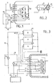
- Fig. 3 shows such a solution applicable in particular to a tube with a shadow mask.
- the adjoining circuits consist of a circuit 30 generating the supply voltage U of the filaments, and video circuits 31, 32 and 33 respectively for the red, green and blue channels.
- Each video circuit has an output of negative polarity connected to the control gate G1 and an output of positive polarity connected to the corresponding cathode KR, KV or KB.
- the blocking voltage between gate G1 and cathode can be for example -70 V and the common output connected to the reference ground potential.
- the respective video signals are transmitted by these circuits over the cathode connections.
- the video circuit of the red channel has a second output of positive polarity, for example at + 100 V, connected to the anode 12.
- the controls are obtained for example by means of current transformers 34, 35 placed on the external connections 9 of heating of the red cannon and supply of the anode 12.
- control circuits 10 The production of the control circuits 10 is based on known techniques, as well as the possible production of additional outputs 3 and / or 13 in the case where the pinout of the tube requires it, that is to say in the absence of an available pin .
Landscapes
- Manufacture Of Electron Tubes, Discharge Lamp Vessels, Lead-In Wires, And The Like (AREA)
- Indicating Measured Values (AREA)
- Video Image Reproduction Devices For Color Tv Systems (AREA)
Applications Claiming Priority (2)
| Application Number | Priority Date | Filing Date | Title |
|---|---|---|---|
| FR8010247A FR2484697A1 (fr) | 1980-05-08 | 1980-05-08 | Tube cathodique polychrome et dispositif de visualisation equipe d'un tel tube |
| FR8010247 | 1980-05-08 |
Publications (2)
| Publication Number | Publication Date |
|---|---|
| EP0040117A1 EP0040117A1 (fr) | 1981-11-18 |
| EP0040117B1 true EP0040117B1 (fr) | 1984-06-13 |
Family
ID=9241743
Family Applications (1)
| Application Number | Title | Priority Date | Filing Date |
|---|---|---|---|
| EP81400605A Expired EP0040117B1 (fr) | 1980-05-08 | 1981-04-15 | Tube cathodique polychrome et dispositif de visualisation équipé d'un tel tube |
Country Status (5)
| Country | Link |
|---|---|
| US (1) | US4433292A (show.php) |
| EP (1) | EP0040117B1 (show.php) |
| JP (1) | JPS579040A (show.php) |
| DE (1) | DE3164120D1 (show.php) |
| FR (1) | FR2484697A1 (show.php) |
Families Citing this family (5)
| Publication number | Priority date | Publication date | Assignee | Title |
|---|---|---|---|---|
| KR940000383B1 (ko) * | 1991-09-19 | 1994-01-19 | 주식회사 금성사 | 음극선관의 스트레이 에미션 방지회로 |
| US5736861A (en) * | 1995-08-07 | 1998-04-07 | Paul A. Keleher | Circuit breaker tester |
| US9625067B2 (en) | 2009-09-01 | 2017-04-18 | Sea Ng Corporation | Clamp suitable for increasing the fatigue life of the butt welds of a pipe pressure vessel which is subsequently bent |
| US20200237622A1 (en) * | 2017-10-16 | 2020-07-30 | Eric Campos | Chambered dispensing devices and methods |
| CN113329710B (zh) * | 2019-01-17 | 2024-11-19 | 奥林巴斯株式会社 | 集中控制装置、集中控制系统以及被控制设备的控制方法 |
Family Cites Families (4)
| Publication number | Priority date | Publication date | Assignee | Title |
|---|---|---|---|---|
| US3623135A (en) * | 1969-09-16 | 1971-11-23 | Gen Electric | Electron gun assembly mounting |
| NL7107749A (show.php) * | 1971-06-05 | 1972-12-07 | ||
| FR2261507A1 (en) * | 1974-02-15 | 1975-09-12 | Normand Equip Ind | Petrol pump dispenser and pricing device - has calculator connected to pump counting circuits |
| US4066311A (en) * | 1977-02-22 | 1978-01-03 | Heath Company | Multiple gun cathode ray tube testing, cleaning, and rejuvenating apparatus |
-
1980
- 1980-05-08 FR FR8010247A patent/FR2484697A1/fr active Granted
-
1981
- 1981-04-15 DE DE8181400605T patent/DE3164120D1/de not_active Expired
- 1981-04-15 EP EP81400605A patent/EP0040117B1/fr not_active Expired
- 1981-05-04 US US06/260,102 patent/US4433292A/en not_active Expired - Fee Related
- 1981-05-06 JP JP6709281A patent/JPS579040A/ja active Pending
Also Published As
| Publication number | Publication date |
|---|---|
| DE3164120D1 (en) | 1984-07-19 |
| EP0040117A1 (fr) | 1981-11-18 |
| FR2484697A1 (fr) | 1981-12-18 |
| JPS579040A (en) | 1982-01-18 |
| FR2484697B1 (show.php) | 1982-06-11 |
| US4433292A (en) | 1984-02-21 |
Similar Documents
| Publication | Publication Date | Title |
|---|---|---|
| EP0040117B1 (fr) | Tube cathodique polychrome et dispositif de visualisation équipé d'un tel tube | |
| US4066311A (en) | Multiple gun cathode ray tube testing, cleaning, and rejuvenating apparatus | |
| US4286148A (en) | Image intensifier tube with photocathode protective circuit | |
| EP0364346B1 (fr) | Boîte à lumière pour dispositif de visualisation avionique | |
| EP0567274A1 (en) | Hollow cathode discharge tube | |
| EP0044239B1 (fr) | Tube intensificateur d'images à micro-canaux et ensemble de prise de vues comprenant un tel tube | |
| US4506191A (en) | Light source cathode ray tube | |
| KR100355504B1 (ko) | Crt용 전자총 | |
| EP0678218B1 (fr) | Méthode pour visualiser le profil d'intensité d'une impulsion laser | |
| CA1088989A (en) | Camera tube with auxiliary illumination | |
| US3986070A (en) | Pick-up tubes | |
| JPH03266342A (ja) | 近接型イメージインテンシファイア | |
| JP2002334674A (ja) | 蛍光表示管及びその駆動方法並びに駆動回路 | |
| FR2517879A1 (fr) | Dispositif de correction des impuretes de couleurs pour des dispositifs d'affichage a panneau plat | |
| US2913610A (en) | Photoemissive tube | |
| JP2005158634A (ja) | 表示装置 | |
| US3459990A (en) | Voltage regulated direct view storage tube precollimation system | |
| JPH0383090A (ja) | 表示素子の組立構造 | |
| US20050093423A1 (en) | Redundant flat lamp system | |
| US6486592B1 (en) | Integral night vision tube contact assembly and method of making | |
| GB1605140A (en) | Image intensifier devices | |
| KR20020056081A (ko) | 음극선관에서 냉음극 보호 장치 | |
| US2734167A (en) | Testing device for cathode ray tubes | |
| JP2005085644A (ja) | 画像表示装置 | |
| US6310448B1 (en) | CRT display device having discharge current limiting resistors in high-voltage supply lines |
Legal Events
| Date | Code | Title | Description |
|---|---|---|---|
| PUAI | Public reference made under article 153(3) epc to a published international application that has entered the european phase |
Free format text: ORIGINAL CODE: 0009012 |
|
| AK | Designated contracting states |
Designated state(s): DE GB IT NL SE |
|
| 17P | Request for examination filed |
Effective date: 19811218 |
|
| ITF | It: translation for a ep patent filed | ||
| GRAA | (expected) grant |
Free format text: ORIGINAL CODE: 0009210 |
|
| AK | Designated contracting states |
Designated state(s): DE GB IT NL SE |
|
| REF | Corresponds to: |
Ref document number: 3164120 Country of ref document: DE Date of ref document: 19840719 |
|
| PLBE | No opposition filed within time limit |
Free format text: ORIGINAL CODE: 0009261 |
|
| STAA | Information on the status of an ep patent application or granted ep patent |
Free format text: STATUS: NO OPPOSITION FILED WITHIN TIME LIMIT |
|
| 26N | No opposition filed | ||
| PGFP | Annual fee paid to national office [announced via postgrant information from national office to epo] |
Ref country code: NL Payment date: 19870430 Year of fee payment: 7 |
|
| PG25 | Lapsed in a contracting state [announced via postgrant information from national office to epo] |
Ref country code: SE Effective date: 19880416 |
|
| ITPR | It: changes in ownership of a european patent |
Owner name: OFFERTA DI LICENZA AL PUBBLICO |
|
| REG | Reference to a national code |
Ref country code: GB Ref legal event code: 746 |
|
| PG25 | Lapsed in a contracting state [announced via postgrant information from national office to epo] |
Ref country code: NL Effective date: 19881101 |
|
| NLV4 | Nl: lapsed or anulled due to non-payment of the annual fee | ||
| ITTA | It: last paid annual fee | ||
| PGFP | Annual fee paid to national office [announced via postgrant information from national office to epo] |
Ref country code: GB Payment date: 19940321 Year of fee payment: 14 |
|
| PGFP | Annual fee paid to national office [announced via postgrant information from national office to epo] |
Ref country code: DE Payment date: 19940326 Year of fee payment: 14 |
|
| EUG | Se: european patent has lapsed |
Ref document number: 81400605.2 Effective date: 19890726 |
|
| PG25 | Lapsed in a contracting state [announced via postgrant information from national office to epo] |
Ref country code: GB Effective date: 19950415 |
|
| GBPC | Gb: european patent ceased through non-payment of renewal fee |
Effective date: 19950415 |
|
| PG25 | Lapsed in a contracting state [announced via postgrant information from national office to epo] |
Ref country code: DE Effective date: 19960103 |