EP0040049A1 - Brake system - Google Patents
Brake system Download PDFInfo
- Publication number
- EP0040049A1 EP0040049A1 EP81302017A EP81302017A EP0040049A1 EP 0040049 A1 EP0040049 A1 EP 0040049A1 EP 81302017 A EP81302017 A EP 81302017A EP 81302017 A EP81302017 A EP 81302017A EP 0040049 A1 EP0040049 A1 EP 0040049A1
- Authority
- EP
- European Patent Office
- Prior art keywords
- brake
- fluid
- piston
- fluid pressure
- pressure
- Prior art date
- Legal status (The legal status is an assumption and is not a legal conclusion. Google has not performed a legal analysis and makes no representation as to the accuracy of the status listed.)
- Granted
Links
- 239000012530 fluid Substances 0.000 claims abstract description 172
- 230000000694 effects Effects 0.000 claims description 11
- 238000000034 method Methods 0.000 claims description 3
- 230000000779 depleting effect Effects 0.000 claims description 2
- 238000012544 monitoring process Methods 0.000 claims 1
- 238000004891 communication Methods 0.000 abstract description 7
- 239000002826 coolant Substances 0.000 description 9
- 238000010276 construction Methods 0.000 description 5
- 230000007246 mechanism Effects 0.000 description 5
- 230000006835 compression Effects 0.000 description 3
- 238000007906 compression Methods 0.000 description 3
- 230000017525 heat dissipation Effects 0.000 description 3
- 230000002093 peripheral effect Effects 0.000 description 3
- 238000003825 pressing Methods 0.000 description 3
- 230000000712 assembly Effects 0.000 description 2
- 238000000429 assembly Methods 0.000 description 2
- 230000008878 coupling Effects 0.000 description 2
- 238000010168 coupling process Methods 0.000 description 2
- 238000005859 coupling reaction Methods 0.000 description 2
- 238000009826 distribution Methods 0.000 description 2
- 230000004048 modification Effects 0.000 description 2
- 238000012986 modification Methods 0.000 description 2
- 230000009471 action Effects 0.000 description 1
- 230000002411 adverse Effects 0.000 description 1
- 230000002153 concerted effect Effects 0.000 description 1
- 238000001816 cooling Methods 0.000 description 1
- 238000011161 development Methods 0.000 description 1
- 239000002783 friction material Substances 0.000 description 1
- 239000000314 lubricant Substances 0.000 description 1
- 238000004519 manufacturing process Methods 0.000 description 1
- 230000013011 mating Effects 0.000 description 1
- 230000004044 response Effects 0.000 description 1
- 230000000717 retained effect Effects 0.000 description 1
- 230000000979 retarding effect Effects 0.000 description 1
- 230000035945 sensitivity Effects 0.000 description 1
Images

Classifications
-
- F—MECHANICAL ENGINEERING; LIGHTING; HEATING; WEAPONS; BLASTING
- F16—ENGINEERING ELEMENTS AND UNITS; GENERAL MEASURES FOR PRODUCING AND MAINTAINING EFFECTIVE FUNCTIONING OF MACHINES OR INSTALLATIONS; THERMAL INSULATION IN GENERAL
- F16D—COUPLINGS FOR TRANSMITTING ROTATION; CLUTCHES; BRAKES
- F16D55/00—Brakes with substantially-radial braking surfaces pressed together in axial direction, e.g. disc brakes
- F16D55/24—Brakes with substantially-radial braking surfaces pressed together in axial direction, e.g. disc brakes with a plurality of axially-movable discs, lamellae, or pads, pressed from one side towards an axially-located member
- F16D55/26—Brakes with substantially-radial braking surfaces pressed together in axial direction, e.g. disc brakes with a plurality of axially-movable discs, lamellae, or pads, pressed from one side towards an axially-located member without self-tightening action
- F16D55/36—Brakes with a plurality of rotating discs all lying side by side
- F16D55/40—Brakes with a plurality of rotating discs all lying side by side actuated by a fluid-pressure device arranged in or one the brake
-
- B—PERFORMING OPERATIONS; TRANSPORTING
- B60—VEHICLES IN GENERAL
- B60T—VEHICLE BRAKE CONTROL SYSTEMS OR PARTS THEREOF; BRAKE CONTROL SYSTEMS OR PARTS THEREOF, IN GENERAL; ARRANGEMENT OF BRAKING ELEMENTS ON VEHICLES IN GENERAL; PORTABLE DEVICES FOR PREVENTING UNWANTED MOVEMENT OF VEHICLES; VEHICLE MODIFICATIONS TO FACILITATE COOLING OF BRAKES
- B60T1/00—Arrangements of braking elements, i.e. of those parts where braking effect occurs specially for vehicles
- B60T1/02—Arrangements of braking elements, i.e. of those parts where braking effect occurs specially for vehicles acting by retarding wheels
- B60T1/06—Arrangements of braking elements, i.e. of those parts where braking effect occurs specially for vehicles acting by retarding wheels acting otherwise than on tread, e.g. employing rim, drum, disc, or transmission or on double wheels
- B60T1/062—Arrangements of braking elements, i.e. of those parts where braking effect occurs specially for vehicles acting by retarding wheels acting otherwise than on tread, e.g. employing rim, drum, disc, or transmission or on double wheels acting on transmission parts
-
- B—PERFORMING OPERATIONS; TRANSPORTING
- B60—VEHICLES IN GENERAL
- B60T—VEHICLE BRAKE CONTROL SYSTEMS OR PARTS THEREOF; BRAKE CONTROL SYSTEMS OR PARTS THEREOF, IN GENERAL; ARRANGEMENT OF BRAKING ELEMENTS ON VEHICLES IN GENERAL; PORTABLE DEVICES FOR PREVENTING UNWANTED MOVEMENT OF VEHICLES; VEHICLE MODIFICATIONS TO FACILITATE COOLING OF BRAKES
- B60T17/00—Component parts, details, or accessories of power brake systems not covered by groups B60T8/00, B60T13/00 or B60T15/00, or presenting other characteristic features
- B60T17/18—Safety devices; Monitoring
-
- F—MECHANICAL ENGINEERING; LIGHTING; HEATING; WEAPONS; BLASTING
- F16—ENGINEERING ELEMENTS AND UNITS; GENERAL MEASURES FOR PRODUCING AND MAINTAINING EFFECTIVE FUNCTIONING OF MACHINES OR INSTALLATIONS; THERMAL INSULATION IN GENERAL
- F16D—COUPLINGS FOR TRANSMITTING ROTATION; CLUTCHES; BRAKES
- F16D55/00—Brakes with substantially-radial braking surfaces pressed together in axial direction, e.g. disc brakes
- F16D2055/0004—Parts or details of disc brakes
- F16D2055/0058—Fully lined, i.e. braking surface extending over the entire disc circumference
Definitions
- the present invention relates generally to brake systems, and in particular to a brake system for a large off-highway vehicle.
- Vehicle friction brake systems, and other friction systems, such as clutches include a plurality of friction members, some of which rotate with respect to the others. Braking is obtained by the frictional engagement between the relatively rotating members. Many of these devices utilize fluid pressure actuated pistons for accomplishing the required movement in the friction components to obtain the frictional engagement.
- the piston or pistons generally include an effective pressure area to which fluid pressure is applied to create a force urging the piston in a brake applying direction.
- the prior art has suggested a variety of piston retraction mechanisms to obtain brake release.
- a brake system In large off-highway vehicles, a brake system is necessary which can bear up under the severe operating conditions.
- the brakes on these vehicles are often subjected to extremely large braking torques and braking applications for extended periods of time.
- the brakes are employed not only to stop vehicle motion, but more importantly are often utilized in retarding vehicle speed when traveling downhill.
- the brake unit must have the capability of dissipating extremely large kinetic energies developed due to the large vehicle mass especially when the brakes are applied for extended time periods. For this and other reasons, a brake system of the multi-disc type is often chosen for this application.
- a typical multi-disc brake includes a series of interleaved, non-rotatable and rotatable friction plates.
- the rotatable plates are operatively connected to the wheel and the non-rotatable plates are coupled or "grounded" to the axle housing or other non-rotating wheel support structure.
- Both the rotatable and non-rotatable plates are mounted for axial movement with respect to the axle and are enclosed within a brake housing.
- Spline connections are generally employed to couple the plates and the brake member to which they are operatively engaged.
- the interleaved plates must be compressed so that their friction surfaces engage to convert the mechanical energy associated with the rotation of the rotatable plates into heat, which is then dissipated.
- the stack of interleaved plates is generally compressed between a wall of the brake chamber in which it is enclosed, and a movable pressure plate.
- a fluid pressure operated piston or pistons generally engage the pressure plate and move it axially into abutting contact with the outermost friction disc causing subsequent engagement of all the plates.
- the discs are sometimes operated in a fluid medium which flows through the brake housing, absorbing heat from the friction discs and then transfers it to a remote heat exchanger.
- the multi-disc brake coupled with a cooling system, provides a brake system having an extremely large torque capacity in a relatively small package.
- the present invention provides a brake system in which the friction brakes are applied by a fluid pressure operated piston which is both actuated and released by fluid pressure under the control of the vehicle operator.
- the brake system includes a source of pressurized fluid and friction brake assemblies mounted within wheel assemblies and operatively connected to the wheels so that upon brake actuation, wheel rotation is retarded or stopped.
- Each friction brake assembly is actuated and released by an operating apparatus which includes at least one piston and an associated piston housing shaped to define a plurality of fluid pressure chambers communicating with a plurality of effective pressure areas on the piston.
- a piston and associated housing are shaped to define three effective pressure areas and three fluid pressure chambers.
- the effective pressure areas on the piston are configured and located such that fluid pressure applied to two of the pressure chambers establishes a brake actuation force on the piston which urges the piston in the "brake applying" direction.
- Fluid pressure applied to the third pressure chamber acts on an effective pressure area of the piston and establishes an opposing force which urges the piston in a "brake releasing" direction.
- the effective pressure areas on the piston are sized so that the brake application force generated by the fluid pressure on the "brake applying" pressure areas is greater than the force generated by the fluid pressure applied to the third or “brake releasing" effective pressure area.
- This configuration allows the friction brake to be actuated by either the concurrent application of pressurized fluid to all three effective pressure areas, or the application of pressure to only the brake applying pressure areas.
- Brake release is obtained by the application of fluid pressure to the brake releasing effective pressure area and the depletion or non-application of fluid pressure to the brake applying effective pressure areas.
- the preferred friction brake assembly is a wet multi-disc type brake which includes a disc pack comprising a plurality of interleaved rotatable and non- rotatable friction discs disposed in a brake chamber.
- the rotatable friction discs are operatively coupled to the wheel by means of a splined coupling member.
- the non-rotatable discs are splined or "grounded" to the brake housing and, hence, the axle housing.
- -An annular pressure plate is disposed adjacent the disc pack and mounted for axial movement with respect to it.
- the fluid pressure actuated piston which is also preferably annular, is located adjacent the pressure plate and is mounted for axial movement towards and away from the plate.
- the disclosed brake construction provides a "high torque" capacity in a relatively small package.
- the construction of the operating piston simplifies the overall braking apparatus in that a separate piston retraction mechanism is not required.
- the actuation and release of the brake piston and the associated brake assembly is accomplished by the application of pressurized fluid to opposing effective pressure areas on the one piston.
- the fluid control system which operates the piston, effects brake application by concurrently applying fluid pressure to all three effective pressure areas.
- the force established by the "brake applying" pressure areas is greater than the force established by the "brake releasing" effective pressure area and thus brake application is effected.
- the retraction of the piston is obtained by depleting the fluid pressure applied to the brake applying effective pressure areas while maintaining the fluid pressure on the brake releasing effective pressure area.
- the fluid pressure control system includes a check valve and a restriction or orifice arrangement in the retraction fluid circuit through which fluid pressure is supplied to the third effective pressure area.
- the check valve and a restricted flow passage are disposed intermediate the pressure source and the brake release chamber.
- the check valve is operative to allow unrestricted fluid flow from the pressure source to the brake release chamber but operates to restrict the rate of fluid flow from the chamber to the source.
- the retraction circuit additionally includes an accumulator, communicating with the retraction fluid chamber, which stores pressurized fluid during brake applicaiton. During brake release,-the fluid in the accumulator also returns to the pressure source through the restriction. The added fluid in the retraction circuit serves to increase the duration of the retraction force on the piston.
- the present invention then provides a brake in which application and release is obtained with a simple but effective piston and control system arrangement. Unliked prior art devices, a separate release system or mechanism, i.e., retraction springs is not required. The overall system is cost effective and reliable due to its simplicity.
- a control valve which, under normal operating conditions, concurrently provides pressurized fluid to the three pressure chambers in response to an operator actuated control.
- the control valve includes a flow control element in the form of spool member, the. position of which is determined by the pressure in the "brake applying" and retraction circuits. As long as .the brake circuits are operating normally, the control valve will allow the communication of pressurized fluid to all three circuits. If a failure occurs resulting in the loss of pressure in either brake applying circuit or the retraction circuit, the spool member will shift from its pressure balanced position, closing off communication between the pressure source and the failed brake circuit. It will also terminate the fluid pressure applied to the brake release circuit and will deplete any fluid pressure remaining in the circuit. Finally, it will supply fluid pressure to only the non-failed "brake applying" circuit.
- the control valve guarantees that pressurized fluid for brake application is available even if a failure occurs in one brake application circuit, so that vehicle motion can be arrested upon brake failure.
- the disclosed control valve controls the flow of pressurized fluid to the brake actuating piston under both normal and emergency conditions. Moreover, it obviates the need for separate service and emergency fluid pressure control systems. It also obviates the need for a separate.mechanical emergency system (spring operated, etc.) as suggested by some prior art devices.
- the simplification of the brake assembly as disclosed by the present invention is obtained without excessive cost or at the expense of reliability.
- the brake system of the present invention includes a friction brake assembly 10 shown in Figure 1 and a brake operating control subsystem shown in Figure 2.
- the brake assembly is mounted to an axle housing 14 and is operatively engaged by a wheel hub assembly, a portion of which is indicated by the reference character 15.
- the axle housing 14 is of conventional construction and surrounds a rotating axle 16.
- the axle 16 extends through the housing and drivingly engages an outboard final drive assembly (not shown) attached to the end of the axle housing.
- a wheel hub assembly 15 is rotatably supported by a pair of roller bearings, one of which is shown as 18, on the axle housing and is driven by the final drive assembly.
- the wheel hub 15, in turn, is coupled to the friction brake assembly 10 by a brake hub adapter 20.
- the brake assembly 10 includes a brake housing 22 formed by an outboard cover 24, an inboard cover 26, and a peripheral cover 28 intermediate the covers 24, 26.
- the three covers are secured and clamped together by a plurality of circumferentially spaced bolts 30 and nuts 31.
- the interfaces between the covers are sealed to prevent fluid leakage by 0-rings 32, 34.
- the brake assembly is secured to a flange 35, integrally formed with the axle housing, by a plurality of cap bolts 3.6.
- the preferred friction brake is of the multi-disc variety.
- the housing 22 encloses a brake disc pack indicated generally as 40, comprising a plurality of interleaved rotatable and non-rotatable discs 42, 44, respectively.
- the rotatable discs 42 are faced with a friction material and are supported and engaged by a rotatable coupling or carrier 46.
- Mating splines on the discs and the carrier are employed to achieve an engagement which prevents relative rotatational movement while allowing relative axial movement between the discs 42 and the carrier 46.
- the splined carrier 46 is also splined to the wheel hub adapter 20, which is bolted to the wheel hub 15 by bolts 48. Rotation of the wheel imparts rotation to the rotatable friction discs through these splined connections.
- the non-rotatable discs 44 are supported and engaged by the peripheral cover 28. Again spline connections are employed to prevent rotation of the discs while allowing relative axial movement between the discs 44 and the cover 28.
- the axial movement of the disc pack 40 with respect to the splined carrier 46 is constrained between predetermined limits by a pair of snap rings 50, 52. More importantly, these snap rings also prevent the splined carrier 46 from being withdrawn from the brake housing when the wheel hub 15 and attached hub adapter 20 are removed from the axle housing. Specifically, the snap ring retainers 50, 52 insure that the spline connection between the hub adapter 20 and the carrier 46 disengages and not the connection between the carrier 46 and the disc pack 40. This configuration allows the wheel to be completely removed from the axle housing without disturbing the brake assembly.
- the braking torque of the brake assembly is developed whenever the disc pack 40 is compressed so that the friction surfaces of the rotatable and non-rotatable discs are engaged.
- an annular pressure plate 60 is disposed adjacent to the inboard disc plate 44a, and is adapted to move axially towards and away from the disc pack 40. Movement of the annular pressure plate 60 towards the disc pack, causes the compression of the pack between an inner surface 62 of the pressure plate, and an inner surface or end wall 64 of the outboard cover 24.
- the pressure plate 60 like the non-rotatable discs 44, is splined to the peripheral housing cover 28 to prevent its rotation.
- movement of the pressure plate 60 is effected by at least one fluid pressure operated piston 70, having a plurality of effective pressure areas.
- the piston 70 is annular and is loosely attached to the pressure plate 60 by a plurality of circumferentially spaced fasteners 69.
- the piston is shaped to define three effective pressure areas.
- the piston 70 includes two annular or cylindrical portions 71, 72 joined by a frustum portion 74.
- An inner surface 76 and an outer surface 78 of the frustum portion 74, and a radial end wall 80 of the annular portion 72 define three effective pressure areas on the piston.
- the piston 70 is mounted in a piston housing formed by the inboard cover 26 and a collar-like insert 81 secured to the inboard cover 26 by a plurality of circumferentially spaced bolts 79.
- the assembled piston housing allows the piston 70 to move axially with respect to the friction disc pack 40 and further defines three annular fluid pressure chambers 82, 84, 86.
- O-rings 87, 88, 89, 90 sealably engage the piston 70 and prevent fluid leakage out of the pressure chambers 82, 84, 86.
- Fluid pressure is communicated to the chambers 82, 84 by drilled Lshaped passages 92, 94, respectively.
- a passage 96 communicates fluid pressure to the fluid chamber 86.
- Pressurized fluid communicated to the "brake applying" fluid chambers 82, 86 establishes a force on the piston which urges it towards abutting engagement with the annular pressure plate 60.
- Pressurized fluid communicated to the retraction chamber 84 creates a force urging the piston 70 and the annular pressure plate 60 away from the disc pack 40.
- the effective pressure areas 76, 78, 80 are approximately equal and the concurrent application of equal fluid pressure to all three areas results in a net force urging the piston 70 into engagement with and attendant movement in the annular pressure plate 60. This movement eventually causes the compression of the disc pack 40 and the development of braking torque.
- the depletion of fluid pressure in chambers 82, 86, coupled with the application of fluid pressure to fluid chamber 84 results in piston retraction.
- coolant fluid is circulated within the brake housing 22.
- the coolant fluid is introduced into the housing at an inlet 100. It is then conveyed through a passage 102 to an annular distribution chamber 104 and into a brake cavity 106.
- the coolant fluid flows from the cavity 106 through radially directed distribution ports 108 in the carrier 46 into the disc housing.
- the coolant fluid then flows between and around the interleaved brake discs and finally into an annular collection chamber 110.
- the heated fluid leaves the brake assembly through an outlet 112 where circuits (not shown) then convey it to a remote heat exchanger (not shown).
- the friction discs include radial flow passages to promote coolant flow between the discs and to increase the heat dissipation rate.
- the direction of coolant flow is generally radial, however, axial flow is provided between adjacent discs by spaces (not shown) in the splines of the carrier 46.
- a face seal 114 including a rotatable portion 114a, attached to the hub adapter 20 and a non-rotatable portion 114b attached to the housing cover 24 prevents coolant loss from the brake housing.
- a similar seal 116 having a rotatable portion 116a, and a non-rotatable portion 116b, prevent the leakage of bearing lubricant between the rotating wheel hub 15 and the axle housing 14.
- a seal 117 prevents coolant fluid leakage between the hub 15 and the hub adapter 20.
- the control system for the vehicle brake includes a piston retraction circuit 118 and a control valve 120 both shown schematically in FIGURE 2.
- the control valve 120 includes a valve body 122 having output ports 124, 126, 128; input pressure ports 130, 132; a reservoir return port 134; and, an internal, cylindrically shaped cavity or bore 136.
- the ports communicate with the bore 136 through respective flow passages 124a, 126a, 128a, 130a, 132a, and 134a.
- the communication between the various ports is controlled by a flow control element 138 in the form of a spool valve, disposed within the bore 136 having three lands 140, 142 and 144.
- the spool valve is pilot pressure operated and under normal operating conditions should assume the central position shown in FIGURE 2.
- the ends of the bore 136 in cooperation with end walls 146, 148 of the lands 140, 144 respectively, define pilot pressure chambers 150, 152 which when pressurized urge the spool 138 towards the right and left, respectively, as reviewed in Figure 2.
- the spool 138 remains in its central position.
- Balance springs 154, 156 are disposed in each pilot pressure chamber and urge the spool valve to its central position in the absence of pressure in the pilot pressure chambers.
- the pilot pressure chamber 150 communicates with the pressure at the output port 128 through a conduit 151 and the pilot pressure chamber 152 communicates with the pressure at the output port 124 through a conduit 155.
- Flow restrictions 157, 158 are disposed in the flow passages 124a and 128a respectively to increase the valves' sensitivity to failures in the control system. The flow restrictions 157, 158 will cause a larger pressure drop in the pilot pressure chambers 150, 152 for a given rate of fluid leakage in the associated fluid circuit.
- a branch flow passage 159 communicates the flow passage 126a with the central bore 136 through a check valve 160.
- the check valve 160 operates to allow fluid flow from the flow passage 126a to the bore 136 but prevents fluid flow from the bore into flow passage 126a. The function of the flow passage 159 will be described later in greater detail.
- the output port 124 communicates with the "brake applying" fluid pressure chamber 82 through a conduit 162.
- the output pressure port 128 communicates with the "brake applying" fluid pressure chamber 86 through a conduit 164.
- the output pressure port 126 communicates with the retraction circuit 118 through a conduit 165.
- the retraction circuit 118 includes a flow restriction 166, a check valve 168, and preferably a pressure accumulator 170 which is supplied with pressure whenever pressure is applied to the retraction fluid pressure chamber 84.
- an operator controlled brake valve (now shown) directs equal and concurrent fluid pressure to the input ports 130, 132.
- the centrally positioned spool valve 138 will allow fluid pressure to flow into all three output ports 124, 126, 128.
- the valve 138 will maintain its central position. Pressurized fluid will then be concurrently applied to all three fluid pressure chambers 82, 84, 86.
- the check valve 168 in the retraction circuit 118 will allow unrestricted fluid flow to the retraction fluid pressure chamber 84 and, hence, all three chambers will receive equal fluid pressures. Under these fluid pressure conditions, the piston 70 will be urged in a "brake applying" direction because the fluid pressure in brake applying chambers 82, 86 is applied to a total effective pressure area, much larger than the effective pressure area in the retraction chamber 84.
- the brake is released whenever the flow of pressurized fluid to the input ports 130, 132 is terminated. In operation, the termination of pressure at these two ports will deplete the pressure in the brake applying pressure chambers 82, 86 very rapidly. The pressure in the retraction chamber 84 will diminish much more slowly due to the combined action of the check valve 168 and the accumulator 170. Once the pressure rise in the retraction chamber ceases, the check valve 168 will close. Stored pressurized fluid from the accumulator 170 will discharge into the retraction chamber 84 and through the restriction 166.
- the control valve 120 will operate to seal off the failed circuit and will deliver fluid pressure to the "non-failed" brake applying fluid pressure .chamber so that brake application can be effected. If a failure occurs in the fluid circuit which is supplied pressure by the output pressure port 124, the loss of fluid pressure in the circuit will be manifested as a loss of pilot pressure in the chamber 152, and as a result, the spool member 138 will be driven to its extreme right position by the pressure in the chamber 150. In this position, the land 140 will block communication between the input port 130 and the output port 124. The land 142 will prevent communication between the input port 132 and the-retraction output port 126.
- any pressure remaining in the retraction circuit will be allowed to drain through the check valve 160 and out the reservoir return port 134. Under these conditions, only the brake applying pressure chamber 86 will be supplied with pressure to effect brake application. Even under these emergency conditions, the brake applying force will be equal to that applied under normal conditions due to the absence of fluid pressure in the retraction fluid pressure chamber 84.
- the pressure in pilot chamber 150 will diminish and the spool member 138 will be driven to its extreme left position.
- the land 144 blocks fluid communication between the input port 132 and both the output ports 126 and '128.
- the land 142 will allow any fluid pressure in the retraction circuit to drain out through the reservoir return port 134. Fluid pressure will be permitted to flow between the input port 130 and the output port 124 so that the "brake applying" fluid pressure chamber 82 is pressurized.
- the check valve 160 in the branch flow passage 159 will prevent the fluid pressure from the input port 130 from charging or pressurizing the failed circuit serviced by either output port 126 or 128.
- This novel control system integrates both the piston actuation and piston retraction functions without complex and costly apparatus.
- the piston retraction is accomplished in a very straightforward and more importantly, a reliable manner.
- the system has a built in brake circuit redundancy so that in the event of failure of either brake applying circuits, excessive fluid loss is prevented and substantial braking ability is retained.
- the fluid pressure control system can be modified to provide fluid pressure to the retraction chamber at all times to essentially provide a "fluid" returned spring.
- the retraction chamber can be supplied with fluid pressure whenever pressurized fluid is not applied to the "brake applying" fluid chambers.
- the piston 70 can be alternately shaped so that the diameter of the cylindrical portion 71 is larger than the diameter of the cylindrical portion 72.
- the outer frusto-conical surface of the frustum 74 would serve as a "brake applying" effective pressure area whereas the corresponding inner frusto-conical surface would serve as a "brake release” effective pressure area.
Abstract
Description
- The present invention relates generally to brake systems, and in particular to a brake system for a large off-highway vehicle.
- Vehicle friction brake systems, and other friction systems, such as clutches, include a plurality of friction members, some of which rotate with respect to the others. Braking is obtained by the frictional engagement between the relatively rotating members. Many of these devices utilize fluid pressure actuated pistons for accomplishing the required movement in the friction components to obtain the frictional engagement. The piston or pistons generally include an effective pressure area to which fluid pressure is applied to create a force urging the piston in a brake applying direction. The prior art has suggested a variety of piston retraction mechanisms to obtain brake release.
- In large off-highway vehicles, a brake system is necessary which can bear up under the severe operating conditions. The brakes on these vehicles are often subjected to extremely large braking torques and braking applications for extended periods of time. The brakes are employed not only to stop vehicle motion, but more importantly are often utilized in retarding vehicle speed when traveling downhill. The brake unit must have the capability of dissipating extremely large kinetic energies developed due to the large vehicle mass especially when the brakes are applied for extended time periods. For this and other reasons, a brake system of the multi-disc type is often chosen for this application.
- A typical multi-disc brake includes a series of interleaved, non-rotatable and rotatable friction plates. The rotatable plates are operatively connected to the wheel and the non-rotatable plates are coupled or "grounded" to the axle housing or other non-rotating wheel support structure. Both the rotatable and non-rotatable plates are mounted for axial movement with respect to the axle and are enclosed within a brake housing. Spline connections are generally employed to couple the plates and the brake member to which they are operatively engaged. To obtain braking in this type of brake, the interleaved plates must be compressed so that their friction surfaces engage to convert the mechanical energy associated with the rotation of the rotatable plates into heat, which is then dissipated. The stack of interleaved plates is generally compressed between a wall of the brake chamber in which it is enclosed, and a movable pressure plate. A fluid pressure operated piston or pistons generally engage the pressure plate and move it axially into abutting contact with the outermost friction disc causing subsequent engagement of all the plates.
- To increase the heat dissipation rate of multi-disc brakes, the discs are sometimes operated in a fluid medium which flows through the brake housing, absorbing heat from the friction discs and then transfers it to a remote heat exchanger. The multi-disc brake, coupled with a cooling system, provides a brake system having an extremely large torque capacity in a relatively small package.
- Some proposed systems have suggested the use of separate retraction springs coupled to the actuating piston to obtain brake release, so that when the pressurized fluid acting on the piston was terminated, the springs would force the piston to its released position. Other systems would employ separate fluid operated retraction pistons to effect the same result. Still others have suggested the utilization of a pressurized coolant fluid to effect or aid in piston release. These suggested retraction mechanisms have generally been complex and costly.
- The emergency application of the vehicle brakes upon failure of the fluid pressure system has been addressed by some prior art brake systems. Suggested mechanisms have included spring biased emergency pistons normally held in a released position by a separate fluid pressure system. Upon brake failure, the emergency pressure system would deplete the pressure applied to the spring biased piston allowing it to engage the vehicle brakes. Other systems have used redundant fluid pressure operated pistons supplied with separate sources of fluid pressure. Still others would suggest the use of a redundant pneumatic pressure and hydraulic pressure operated disc brake having separate actuating pistons operated by the respective pressure sources. In many of these suggested systems, the apparatus added significant complexity to the brake housing and more importantly adversely affected the brake assembly size, making them unsuitable for many vehicle applications having brake size constraints. In those systems which would suggest the use of separate source of pressurized fluid, the control system necessary to effect reliable operation would be costly to manufacture and maintain.
- The present invention provides a brake system in which the friction brakes are applied by a fluid pressure operated piston which is both actuated and released by fluid pressure under the control of the vehicle operator.
- In a preferred form, the brake system includes a source of pressurized fluid and friction brake assemblies mounted within wheel assemblies and operatively connected to the wheels so that upon brake actuation, wheel rotation is retarded or stopped. Each friction brake assembly is actuated and released by an operating apparatus which includes at least one piston and an associated piston housing shaped to define a plurality of fluid pressure chambers communicating with a plurality of effective pressure areas on the piston.
- In a preferred construction, a piston and associated housing are shaped to define three effective pressure areas and three fluid pressure chambers. The effective pressure areas on the piston are configured and located such that fluid pressure applied to two of the pressure chambers establishes a brake actuation force on the piston which urges the piston in the "brake applying" direction. Fluid pressure applied to the third pressure chamber acts on an effective pressure area of the piston and establishes an opposing force which urges the piston in a "brake releasing" direction.
- In the preferred embodiment, the effective pressure areas on the piston are sized so that the brake application force generated by the fluid pressure on the "brake applying" pressure areas is greater than the force generated by the fluid pressure applied to the third or "brake releasing" effective pressure area. This configuration allows the friction brake to be actuated by either the concurrent application of pressurized fluid to all three effective pressure areas, or the application of pressure to only the brake applying pressure areas. Brake release is obtained by the application of fluid pressure to the brake releasing effective pressure area and the depletion or non-application of fluid pressure to the brake applying effective pressure areas.
- The preferred friction brake assembly is a wet multi-disc type brake which includes a disc pack comprising a plurality of interleaved rotatable and non- rotatable friction discs disposed in a brake chamber. The rotatable friction discs are operatively coupled to the wheel by means of a splined coupling member. The non-rotatable discs are splined or "grounded" to the brake housing and, hence, the axle housing. -An annular pressure plate is disposed adjacent the disc pack and mounted for axial movement with respect to it. The fluid pressure actuated piston, which is also preferably annular, is located adjacent the pressure plate and is mounted for axial movement towards and away from the plate. When the annular piston is driven in the brake application direction by fluid pressure, it abuttingly engages the pressure plate and in concerted motion, causes the pressure plate to compress the disc pack between it and the opposite brake chamber wall. The engagement of the interleaved rotatable and non-rotatable discs effects wheel braking.
- The disclosed brake construction provides a "high torque" capacity in a relatively small package. The construction of the operating piston simplifies the overall braking apparatus in that a separate piston retraction mechanism is not required. The actuation and release of the brake piston and the associated brake assembly is accomplished by the application of pressurized fluid to opposing effective pressure areas on the one piston.
- According to a feature of the invention, the fluid control system which operates the piston, effects brake application by concurrently applying fluid pressure to all three effective pressure areas. The force established by the "brake applying" pressure areas is greater than the force established by the "brake releasing" effective pressure area and thus brake application is effected. The retraction of the piston is obtained by depleting the fluid pressure applied to the brake applying effective pressure areas while maintaining the fluid pressure on the brake releasing effective pressure area.
- To accomplish this feature, the fluid pressure control system includes a check valve and a restriction or orifice arrangement in the retraction fluid circuit through which fluid pressure is supplied to the third effective pressure area. During brake application all three pressure chambers are supplied with fluid pressure by three non-communicating fluid pressure circuits. The check valve and a restricted flow passage are disposed intermediate the pressure source and the brake release chamber. The check valve is operative to allow unrestricted fluid flow from the pressure source to the brake release chamber but operates to restrict the rate of fluid flow from the chamber to the source. When the application of pressurized fluid to the three pressure chambers is terminated, the pressure in the brake applying chambers will deplete very rapidly whereas the pressure in the brake releasing chamber will deplete very slowly as the fluid pressure from the release chamber bleeds through the restricted passage.
- In a more preferred embodiment, the retraction circuit additionally includes an accumulator, communicating with the retraction fluid chamber, which stores pressurized fluid during brake applicaiton. During brake release,-the fluid in the accumulator also returns to the pressure source through the restriction. The added fluid in the retraction circuit serves to increase the duration of the retraction force on the piston.
- The present invention then provides a brake in which application and release is obtained with a simple but effective piston and control system arrangement. Unliked prior art devices, a separate release system or mechanism, i.e., retraction springs is not required. The overall system is cost effective and reliable due to its simplicity.
- According to another feature of the invention, a control valve is disclosed which, under normal operating conditions, concurrently provides pressurized fluid to the three pressure chambers in response to an operator actuated control. The control valve includes a flow control element in the form of spool member, the. position of which is determined by the pressure in the "brake applying" and retraction circuits. As long as .the brake circuits are operating normally, the control valve will allow the communication of pressurized fluid to all three circuits. If a failure occurs resulting in the loss of pressure in either brake applying circuit or the retraction circuit, the spool member will shift from its pressure balanced position, closing off communication between the pressure source and the failed brake circuit. It will also terminate the fluid pressure applied to the brake release circuit and will deplete any fluid pressure remaining in the circuit. Finally, it will supply fluid pressure to only the non-failed "brake applying" circuit. The control valve guarantees that pressurized fluid for brake application is available even if a failure occurs in one brake application circuit, so that vehicle motion can be arrested upon brake failure.
- The disclosed control valve controls the flow of pressurized fluid to the brake actuating piston under both normal and emergency conditions. Moreover, it obviates the need for separate service and emergency fluid pressure control systems. It also obviates the need for a separate.mechanical emergency system (spring operated, etc.) as suggested by some prior art devices. The simplification of the brake assembly as disclosed by the present invention is obtained without excessive cost or at the expense of reliability.
- It is an object of the present invention to provide a vehicle brake system in which friction brakes are actuated and released by a fluid pressure operated piston having a plurality of effective pressure areas.
- It is another object of this invention to provide a method for actuating and releasing a friction brake by a pressurized fluid acting upon a piston having a plurality of effective pressure areas.
- It is a further object of this invention to provide a control valve which controls the flow of pressurized fluid to multiple chambers communicating with associated effective pressure areas on an actuating piston.
- It is a further object of this invention to provide a control valve which controls the application of fluid pressure to the actuating piston under both normal and emergency braking conditions.
- Further objects and advantages will be found in reading the following detailed description of a preferred embodiment made with reference to the accompanying drawings.
- In the drawings forming a part of this application:
- FIGURE 1 is a cross-sectional view of a multi-disc brake embodying features of the present invention.
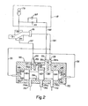
- FIGURE 2 is a schematic representation of the control system and brake operating piston constructed in accordance with the invention.
- The brake system of the present invention includes a
friction brake assembly 10 shown in Figure 1 and a brake operating control subsystem shown in Figure 2. The brake assembly is mounted to an axle housing 14 and is operatively engaged by a wheel hub assembly, a portion of which is indicated by thereference character 15. - The axle housing 14 is of conventional construction and surrounds a
rotating axle 16. Theaxle 16 extends through the housing and drivingly engages an outboard final drive assembly (not shown) attached to the end of the axle housing. Awheel hub assembly 15 is rotatably supported by a pair of roller bearings, one of which is shown as 18, on the axle housing and is driven by the final drive assembly. Thewheel hub 15, in turn, is coupled to thefriction brake assembly 10 by abrake hub adapter 20. - The
brake assembly 10 includes abrake housing 22 formed by anoutboard cover 24, aninboard cover 26, and aperipheral cover 28 intermediate thecovers bolts 30 and nuts 31. The interfaces between the covers are sealed to prevent fluid leakage by 0-rings flange 35, integrally formed with the axle housing, by a plurality of cap bolts 3.6. - The preferred friction brake is of the multi-disc variety. In accordance with this embodiment, the
housing 22 encloses a brake disc pack indicated generally as 40, comprising a plurality of interleaved rotatable andnon-rotatable discs rotatable discs 42 are faced with a friction material and are supported and engaged by a rotatable coupling orcarrier 46. Mating splines on the discs and the carrier are employed to achieve an engagement which prevents relative rotatational movement while allowing relative axial movement between thediscs 42 and thecarrier 46. Thesplined carrier 46 is also splined to thewheel hub adapter 20, which is bolted to thewheel hub 15 bybolts 48. Rotation of the wheel imparts rotation to the rotatable friction discs through these splined connections. - The
non-rotatable discs 44 are supported and engaged by theperipheral cover 28. Again spline connections are employed to prevent rotation of the discs while allowing relative axial movement between thediscs 44 and thecover 28. - The axial movement of the disc pack 40 with respect to the
splined carrier 46 is constrained between predetermined limits by a pair of snap rings 50, 52. More importantly, these snap rings also prevent thesplined carrier 46 from being withdrawn from the brake housing when thewheel hub 15 and attachedhub adapter 20 are removed from the axle housing. Specifically, thesnap ring retainers hub adapter 20 and thecarrier 46 disengages and not the connection between thecarrier 46 and the disc pack 40. This configuration allows the wheel to be completely removed from the axle housing without disturbing the brake assembly. - The braking torque of the brake assembly is developed whenever the disc pack 40 is compressed so that the friction surfaces of the rotatable and non-rotatable discs are engaged. To accomplish this compression, an annular pressure plate 60 is disposed adjacent to the
inboard disc plate 44a, and is adapted to move axially towards and away from the disc pack 40. Movement of the annular pressure plate 60 towards the disc pack, causes the compression of the pack between aninner surface 62 of the pressure plate, and an inner surface or endwall 64 of theoutboard cover 24. The pressure plate 60, like thenon-rotatable discs 44, is splined to theperipheral housing cover 28 to prevent its rotation. - According to an important feature of this inven- tion, movement of the pressure plate 60 is effected by at least one fluid pressure operated
piston 70, having a plurality of effective pressure areas. Thepiston 70 is annular and is loosely attached to the pressure plate 60 by a plurality of circumferentially spaced fasteners 69. In the preferred form, the piston is shaped to define three effective pressure areas. As shown in Figures 1 and 2, thepiston 70 includes two annular or cylindrical portions 71, 72 joined by afrustum portion 74. An inner surface 76 and anouter surface 78 of thefrustum portion 74, and aradial end wall 80 of the annular portion 72 define three effective pressure areas on the piston. Thepiston 70 is mounted in a piston housing formed by theinboard cover 26 and a collar-like insert 81 secured to theinboard cover 26 by a plurality of circumferentially spacedbolts 79. The assembled piston housing allows thepiston 70 to move axially with respect to the friction disc pack 40 and further defines three annularfluid pressure chambers rings piston 70 and prevent fluid leakage out of thepressure chambers - Fluid pressure is communicated to the
chambers Lshaped passages 92, 94, respectively. Apassage 96 communicates fluid pressure to thefluid chamber 86. - Pressurized fluid communicated to the "brake applying"
fluid chambers retraction chamber 84 creates a force urging thepiston 70 and the annular pressure plate 60 away from the disc pack 40. In a preferred brake assembly, theeffective pressure areas piston 70 into engagement with and attendant movement in the annular pressure plate 60. This movement eventually causes the compression of the disc pack 40 and the development of braking torque. The depletion of fluid pressure inchambers fluid chamber 84 results in piston retraction. - To increase the heat dissipation rate of the brake assembly, coolant fluid is circulated within the
brake housing 22. The coolant fluid is introduced into the housing at an inlet 100. It is then conveyed through apassage 102 to anannular distribution chamber 104 and into abrake cavity 106. The coolant fluid flows from thecavity 106 through radially directeddistribution ports 108 in thecarrier 46 into the disc housing. The coolant fluid then flows between and around the interleaved brake discs and finally into anannular collection chamber 110. The heated fluid leaves the brake assembly through anoutlet 112 where circuits (not shown) then convey it to a remote heat exchanger (not shown). The friction discs include radial flow passages to promote coolant flow between the discs and to increase the heat dissipation rate. The direction of coolant flow is generally radial, however, axial flow is provided between adjacent discs by spaces (not shown) in the splines of thecarrier 46. - A
face seal 114, including arotatable portion 114a, attached to thehub adapter 20 and a non-rotatable portion 114b attached to thehousing cover 24 prevents coolant loss from the brake housing. Asimilar seal 116 having a rotatable portion 116a, and a non-rotatable portion 116b, prevent the leakage of bearing lubricant between therotating wheel hub 15 and the axle housing 14. Aseal 117 prevents coolant fluid leakage between thehub 15 and thehub adapter 20. - In accordance with the features of the invention, the control system for the vehicle brake includes a
piston retraction circuit 118 and acontrol valve 120 both shown schematically in FIGURE 2. Thecontrol valve 120 includes avalve body 122 havingoutput ports input pressure ports reservoir return port 134; and, an internal, cylindrically shaped cavity or bore 136. The ports communicate with thebore 136 throughrespective flow passages bore 136 having threelands - The spool valve is pilot pressure operated and under normal operating conditions should assume the central position shown in FIGURE 2. The ends of the
bore 136 in cooperation withend walls 146, 148 of thelands 140, 144 respectively, definepilot pressure chambers chambers pilot pressure chamber 150 communicates with the pressure at theoutput port 128 through aconduit 151 and thepilot pressure chamber 152 communicates with the pressure at theoutput port 124 through aconduit 155.Flow restrictions flow passages flow restrictions pilot pressure chambers - The position of the spool member 138 illustrated in Figure 2 allows the
port 130 to communicate withoutput port 124 andinput port 132 to communicate with both theoutput port 126 and theoutput port 128. Abranch flow passage 159 communicates theflow passage 126a with thecentral bore 136 through acheck valve 160. Thecheck valve 160 operates to allow fluid flow from theflow passage 126a to thebore 136 but prevents fluid flow from the bore intoflow passage 126a. The function of theflow passage 159 will be described later in greater detail. - As illustrated in FIGURE 2, the
output port 124 communicates with the "brake applying"fluid pressure chamber 82 through aconduit 162. Theoutput pressure port 128 communicates with the "brake applying"fluid pressure chamber 86 through a conduit 164. Theoutput pressure port 126 communicates with theretraction circuit 118 through aconduit 165. - The
retraction circuit 118 includes aflow restriction 166, acheck valve 168, and preferably a pressure accumulator 170 which is supplied with pressure whenever pressure is applied to the retractionfluid pressure chamber 84. - During normal brake operation, the movement of an operator controlled brake valve (now shown) directs equal and concurrent fluid pressure to the
input ports output ports pilot pressure chambers fluid pressure chambers check valve 168 in theretraction circuit 118 will allow unrestricted fluid flow to the retractionfluid pressure chamber 84 and, hence, all three chambers will receive equal fluid pressures. Under these fluid pressure conditions, thepiston 70 will be urged in a "brake applying" direction because the fluid pressure inbrake applying chambers retraction chamber 84. - The brake is released whenever the flow of pressurized fluid to the
input ports pressure chambers retraction chamber 84 will diminish much more slowly due to the combined action of thecheck valve 168 and the accumulator 170. Once the pressure rise in the retraction chamber ceases, thecheck valve 168 will close. Stored pressurized fluid from the accumulator 170 will discharge into theretraction chamber 84 and through therestriction 166. The flow of pressurized fluid from the accumulator 170 to theretraction chamber 84 will cause the retraction force applied by fluid in the retraction chamber (and the accumulator) to be maintained for a period of time after the pressure inchambers piston 70 to its retracted position. - In the event of failure in any of the output circuits, the
control valve 120 will operate to seal off the failed circuit and will deliver fluid pressure to the "non-failed" brake applying fluid pressure .chamber so that brake application can be effected. If a failure occurs in the fluid circuit which is supplied pressure by theoutput pressure port 124, the loss of fluid pressure in the circuit will be manifested as a loss of pilot pressure in thechamber 152, and as a result, the spool member 138 will be driven to its extreme right position by the pressure in thechamber 150. In this position, theland 140 will block communication between theinput port 130 and theoutput port 124. Theland 142 will prevent communication between theinput port 132 and the-retraction output port 126. Any pressure remaining in the retraction circuit will be allowed to drain through thecheck valve 160 and out thereservoir return port 134. Under these conditions, only the brake applyingpressure chamber 86 will be supplied with pressure to effect brake application. Even under these emergency conditions, the brake applying force will be equal to that applied under normal conditions due to the absence of fluid pressure in the retractionfluid pressure chamber 84. - Should a failure occur in either the
retraction circuit 118 or the circuit supplied with fluid pressure by theoutput port 128, the pressure inpilot chamber 150 will diminish and the spool member 138 will be driven to its extreme left position. In this position, the land 144 blocks fluid communication between theinput port 132 and both theoutput ports 126 and '128. As in the previous case, theland 142 will allow any fluid pressure in the retraction circuit to drain out through thereservoir return port 134. Fluid pressure will be permitted to flow between theinput port 130 and theoutput port 124 so that the "brake applying"fluid pressure chamber 82 is pressurized. Thecheck valve 160 in thebranch flow passage 159 will prevent the fluid pressure from theinput port 130 from charging or pressurizing the failed circuit serviced by eitheroutput port - This novel control system integrates both the piston actuation and piston retraction functions without complex and costly apparatus. The piston retraction is accomplished in a very straightforward and more importantly, a reliable manner. Moreover, the system has a built in brake circuit redundancy so that in the event of failure of either brake applying circuits, excessive fluid loss is prevented and substantial braking ability is retained.
- Although the invention has been described with a certain degree of particularity, various modifications and changes can be made to it by those skilled in the art without departing from the spirit or scope of the invention as described. For instance, a brake assembly construction which includes multiple fluid pressure actuated pistons each having a plurality of effective pressure areas is encompassed. Another contemplated modification would be a fluid-operated piston having unequal effective pressure areas to which correspondingly unequal fluid pressures are applied to effect the requisite "applying" and "releasing" force relationship.
- The fluid pressure control system can be modified to provide fluid pressure to the retraction chamber at all times to essentially provide a "fluid" returned spring. Alternately, the retraction chamber can be supplied with fluid pressure whenever pressurized fluid is not applied to the "brake applying" fluid chambers.
- The
piston 70 can be alternately shaped so that the diameter of the cylindrical portion 71 is larger than the diameter of the cylindrical portion 72. In this configuration the outer frusto-conical surface of thefrustum 74 would serve as a "brake applying" effective pressure area whereas the corresponding inner frusto-conical surface would serve as a "brake release" effective pressure area. These and other changes can be made to the brake system without departing from the spirit or scope of the invention as hereinafter claimed.
Claims (12)
Applications Claiming Priority (2)
| Application Number | Priority Date | Filing Date | Title |
|---|---|---|---|
| US148538 | 1980-05-09 | ||
| US06/148,538 US4562902A (en) | 1980-05-09 | 1980-05-09 | Brake system |
Publications (2)
| Publication Number | Publication Date |
|---|---|
| EP0040049A1 true EP0040049A1 (en) | 1981-11-18 |
| EP0040049B1 EP0040049B1 (en) | 1985-09-04 |
Family
ID=22526197
Family Applications (1)
| Application Number | Title | Priority Date | Filing Date |
|---|---|---|---|
| EP81302017A Expired EP0040049B1 (en) | 1980-05-09 | 1981-05-07 | Brake system |
Country Status (8)
| Country | Link |
|---|---|
| US (1) | US4562902A (en) |
| EP (1) | EP0040049B1 (en) |
| JP (1) | JPS5733235A (en) |
| AU (1) | AU542251B2 (en) |
| CA (1) | CA1180037A (en) |
| DE (1) | DE3172110D1 (en) |
| MX (1) | MX152845A (en) |
| ZA (1) | ZA812970B (en) |
Cited By (3)
| Publication number | Priority date | Publication date | Assignee | Title |
|---|---|---|---|---|
| FR2555685A1 (en) * | 1983-11-30 | 1985-05-31 | Dba | Braking system comprising at least one sliding brake disc |
| EP0143709A2 (en) * | 1983-11-30 | 1985-06-05 | BENDIX France | Brake system comprising at least one floating brake disc |
| AT513902A1 (en) * | 2013-02-01 | 2014-08-15 | Wacker Neuson Linz Gmbh | Device for braking a work machine |
Families Citing this family (11)
| Publication number | Priority date | Publication date | Assignee | Title |
|---|---|---|---|---|
| US5174420A (en) * | 1991-05-02 | 1992-12-29 | Clark Equipment Company | Wet disc brake |
| US5794751A (en) * | 1996-10-02 | 1998-08-18 | Sanford Acquisition Company | Piston for torque transmitting systems |
| EP1350979A3 (en) * | 1996-12-31 | 2004-01-07 | RANCOURT, Yvon | Improved disc brake assembly |
| US6253882B1 (en) * | 1999-02-22 | 2001-07-03 | White Hydraulics, Inc. | Motor with symmetric braking system |
| JP4613588B2 (en) * | 2004-11-11 | 2011-01-19 | トヨタ自動車株式会社 | Friction engagement device for automatic transmission |
| US8491434B2 (en) * | 2010-12-10 | 2013-07-23 | Caterpillar Inc. | Transmission assembly having variable force clutch |
| US9011287B2 (en) | 2012-06-01 | 2015-04-21 | Caterpillar Inc. | Dual piston transmission clutch |
| JP6350441B2 (en) * | 2014-10-30 | 2018-07-04 | マツダ株式会社 | Brake device for transmission |
| CA2969351C (en) * | 2014-12-27 | 2023-03-14 | Kinetics Drive Solutions Inc. | Improved cooling system for multi-disc brake assembly |
| JP6512197B2 (en) * | 2016-09-15 | 2019-05-15 | 株式会社豊田自動織機 | Wet brake |
| CN116025706B (en) * | 2022-12-12 | 2024-02-27 | 荣成市兴银机械工程有限公司 | Vehicle emergency braking parking brake and braking method thereof |
Citations (6)
| Publication number | Priority date | Publication date | Assignee | Title |
|---|---|---|---|---|
| FR2102141A1 (en) * | 1970-08-08 | 1972-04-07 | Girling Ltd | |
| GB1337437A (en) * | 1970-08-08 | 1973-11-14 | Girling Ltd | Hydraulic braking system for vehicles |
| DE2510193A1 (en) * | 1975-03-08 | 1976-09-16 | Wabco Westinghouse Gmbh | PRESSURE-ACTUATED DISC BRAKE, IN PARTICULAR FOR VEHICLES |
| US4057297A (en) * | 1976-06-28 | 1977-11-08 | Beck Henry E | Brake mechanism with spring applied fluid pressure released assembly |
| US4096926A (en) * | 1969-12-02 | 1978-06-27 | Hermann Klaue | Actuator and cooling structure for disk brakes |
| US4184573A (en) * | 1978-10-05 | 1980-01-22 | Walter Kidde & Company, Inc. | Double-acting disc brake having floating cylinder head |
Family Cites Families (23)
| Publication number | Priority date | Publication date | Assignee | Title |
|---|---|---|---|---|
| DE451918C (en) * | 1926-08-03 | 1927-11-04 | Fried Krupp Akt Ges | Friction clutch |
| US2195214A (en) * | 1938-09-01 | 1940-03-26 | D A Walton | Fluid brake |
| BE468677A (en) * | 1939-07-05 | |||
| US2527290A (en) * | 1944-06-22 | 1950-10-24 | Bethlehem Supply Company | Friction brake applied and released by fluid pressure |
| US2502547A (en) * | 1948-05-11 | 1950-04-04 | Denison Eng Co | Hydraulic apparatus |
| US2519900A (en) * | 1948-12-10 | 1950-08-22 | Hpm Dev Corp | Control circuit for multiple hydraulic press systems |
| US2683966A (en) * | 1953-06-08 | 1954-07-20 | Oilgear Co | Hydraulic press |
| US2823770A (en) * | 1956-03-21 | 1958-02-18 | Gen Motors Corp | Actuating mechanism for a friction brake |
| US2928504A (en) * | 1957-03-12 | 1960-03-15 | Lambert & Brake Corp | Heavy duty oil-cooled friction device |
| US3105582A (en) * | 1961-03-13 | 1963-10-01 | Twin Disc Clutch Co | Oil pressure actuated clutch |
| US3202253A (en) * | 1961-12-04 | 1965-08-24 | Clark Equipment Co | Clutch cooling means |
| US3217851A (en) * | 1962-01-23 | 1965-11-16 | Caterpillar Tractor Co | Fluid-actuated rotating clutch |
| US3198295A (en) * | 1963-02-21 | 1965-08-03 | Caterpillar Tractor Co | Friction couple cooling device |
| US3580368A (en) * | 1969-06-02 | 1971-05-25 | Gen Motors Corp | Disc brake cooling means and pump drive mechanism |
| DE2008052A1 (en) * | 1970-02-21 | 1971-09-02 | ||
| DE2046135A1 (en) * | 1970-09-18 | 1972-03-23 | Dr.-Ing. H.C. F. Porsche Kg, 7000 Stuttgart-Zuffenhausen | Safety device for dual-circuit brake systems in motor vehicles |
| US3690429A (en) * | 1971-07-15 | 1972-09-12 | Honda Motor Co Ltd | Clutch with dual pistons and springs |
| JPS4840286U (en) * | 1971-09-16 | 1973-05-21 | ||
| US4207969A (en) * | 1974-01-14 | 1980-06-17 | Robert Howell Industries | Wet disc friction device |
| US3941219A (en) * | 1975-01-31 | 1976-03-02 | Caterpillar Tractor Co. | Dual piston brake arrangement and cooling circuit therefor |
| US3927737A (en) * | 1974-11-11 | 1975-12-23 | Caterpillar Tractor Co | Annular dual piston brake arrangement |
| US3946837A (en) * | 1974-12-26 | 1976-03-30 | Rohr Industries, Inc. | Disc brake and actuator assembly |
| GB1504073A (en) * | 1975-08-27 | 1978-03-15 | Caterpillar Tractor Co | Annular single piston brake arrangement |
-
1980
- 1980-05-09 US US06/148,538 patent/US4562902A/en not_active Expired - Lifetime
-
1981
- 1981-05-05 ZA ZA00812970A patent/ZA812970B/en unknown
- 1981-05-07 DE DE8181302017T patent/DE3172110D1/en not_active Expired
- 1981-05-07 JP JP6772181A patent/JPS5733235A/en active Pending
- 1981-05-07 EP EP81302017A patent/EP0040049B1/en not_active Expired
- 1981-05-08 CA CA000377190A patent/CA1180037A/en not_active Expired
- 1981-05-08 AU AU70404/81A patent/AU542251B2/en not_active Ceased
- 1981-05-11 MX MX187242A patent/MX152845A/en unknown
Patent Citations (7)
| Publication number | Priority date | Publication date | Assignee | Title |
|---|---|---|---|---|
| US4096926A (en) * | 1969-12-02 | 1978-06-27 | Hermann Klaue | Actuator and cooling structure for disk brakes |
| FR2102141A1 (en) * | 1970-08-08 | 1972-04-07 | Girling Ltd | |
| GB1337437A (en) * | 1970-08-08 | 1973-11-14 | Girling Ltd | Hydraulic braking system for vehicles |
| DE2510193A1 (en) * | 1975-03-08 | 1976-09-16 | Wabco Westinghouse Gmbh | PRESSURE-ACTUATED DISC BRAKE, IN PARTICULAR FOR VEHICLES |
| GB1512224A (en) * | 1975-03-08 | 1978-05-24 | Wabco Westinghouse Gmbh | Pressure medium operated disc brake |
| US4057297A (en) * | 1976-06-28 | 1977-11-08 | Beck Henry E | Brake mechanism with spring applied fluid pressure released assembly |
| US4184573A (en) * | 1978-10-05 | 1980-01-22 | Walter Kidde & Company, Inc. | Double-acting disc brake having floating cylinder head |
Cited By (6)
| Publication number | Priority date | Publication date | Assignee | Title |
|---|---|---|---|---|
| FR2555685A1 (en) * | 1983-11-30 | 1985-05-31 | Dba | Braking system comprising at least one sliding brake disc |
| EP0143709A2 (en) * | 1983-11-30 | 1985-06-05 | BENDIX France | Brake system comprising at least one floating brake disc |
| EP0143709A3 (en) * | 1983-11-30 | 1985-07-17 | Societe Anonyme D.B.A. | Brake system comprising at least one floating brake disc |
| FR2565309A2 (en) * | 1983-11-30 | 1985-12-06 | Dba | Brake system comprising at least one sliding brake disc. |
| US4614254A (en) * | 1983-11-30 | 1986-09-30 | Societe Anonyme D.B.A. | Braking system incorporating at least one sliding brake disc |
| AT513902A1 (en) * | 2013-02-01 | 2014-08-15 | Wacker Neuson Linz Gmbh | Device for braking a work machine |
Also Published As
| Publication number | Publication date |
|---|---|
| DE3172110D1 (en) | 1985-10-10 |
| MX152845A (en) | 1986-06-18 |
| JPS5733235A (en) | 1982-02-23 |
| EP0040049B1 (en) | 1985-09-04 |
| AU542251B2 (en) | 1985-02-14 |
| US4562902A (en) | 1986-01-07 |
| AU7040481A (en) | 1981-11-12 |
| CA1180037A (en) | 1984-12-27 |
| ZA812970B (en) | 1982-11-24 |
Similar Documents
| Publication | Publication Date | Title |
|---|---|---|
| EP0512252B1 (en) | Wet-friction disc brake | |
| EP0040049B1 (en) | Brake system | |
| US4655326A (en) | Cooling system for planetary wheel end with wet brake | |
| AU654457B2 (en) | Disc brake with powered integral parking mechanism | |
| US4646880A (en) | Planetary wheel end with wet brake | |
| EP2895739B1 (en) | Combined motor and brake with rotating brake-release piston | |
| US5012901A (en) | Self-energizing disc brakes | |
| US4024936A (en) | Combination vehicle service and parking brake | |
| KR20010050191A (en) | Automatic transmission with dual gain multi-disk friction device | |
| WO2009059720A1 (en) | Brake for utility vehicle | |
| US9551222B2 (en) | Freewheel hydraulic motor | |
| US5050939A (en) | Fail-safe wheel service brake system | |
| US6153988A (en) | Arrangement for operating an electromagnetic brake of a vehicle | |
| EP0592603A4 (en) | Direct drive axle brake and cooling system. | |
| US4030576A (en) | Disc brake assembly including a self-contained actuator with wear take-up and anti-drag device | |
| US5228543A (en) | Sealed wet disc brake for vehicles | |
| EP1153225B1 (en) | Motor with symmetric braking system | |
| US3526302A (en) | Drive train brake | |
| US5029682A (en) | Brake system for full-track vehicles | |
| US11287003B2 (en) | Integral unit for service brake and fail-safe park brake | |
| US4723637A (en) | Torque limited brake | |
| US4448458A (en) | Shut-off cylinder for a supply accumulator of a hydraulic brake system | |
| GB1572153A (en) | Brake actuating means | |
| SU1425101A1 (en) | Vehicle motor-wheel | |
| EP0315443A1 (en) | Improvements in vehicle disc brakes of the liquid cooled type |
Legal Events
| Date | Code | Title | Description |
|---|---|---|---|
| PUAI | Public reference made under article 153(3) epc to a published international application that has entered the european phase |
Free format text: ORIGINAL CODE: 0009012 |
|
| AK | Designated contracting states |
Designated state(s): BE DE FR GB IT SE |
|
| 17P | Request for examination filed |
Effective date: 19820506 |
|
| ITF | It: translation for a ep patent filed |
Owner name: SOCIETA' ITALIANA BREVETTI S.P.A. |
|
| GRAA | (expected) grant |
Free format text: ORIGINAL CODE: 0009210 |
|
| RAP1 | Party data changed (applicant data changed or rights of an application transferred) |
Owner name: CLARK EQUIPMENT COMPANY |
|
| AK | Designated contracting states |
Designated state(s): BE DE FR GB IT SE |
|
| PG25 | Lapsed in a contracting state [announced via postgrant information from national office to epo] |
Ref country code: BE Effective date: 19850904 |
|
| PG25 | Lapsed in a contracting state [announced via postgrant information from national office to epo] |
Ref country code: SE Effective date: 19850930 |
|
| REF | Corresponds to: |
Ref document number: 3172110 Country of ref document: DE Date of ref document: 19851010 |
|
| ET | Fr: translation filed | ||
| PLBE | No opposition filed within time limit |
Free format text: ORIGINAL CODE: 0009261 |
|
| STAA | Information on the status of an ep patent application or granted ep patent |
Free format text: STATUS: NO OPPOSITION FILED WITHIN TIME LIMIT |
|
| 26N | No opposition filed | ||
| PG25 | Lapsed in a contracting state [announced via postgrant information from national office to epo] |
Ref country code: GB Effective date: 19880507 |
|
| PG25 | Lapsed in a contracting state [announced via postgrant information from national office to epo] |
Ref country code: FR Free format text: LAPSE BECAUSE OF NON-PAYMENT OF DUE FEES Effective date: 19890131 |
|
| GBPC | Gb: european patent ceased through non-payment of renewal fee | ||
| REG | Reference to a national code |
Ref country code: FR Ref legal event code: ST |
|
| PG25 | Lapsed in a contracting state [announced via postgrant information from national office to epo] |
Ref country code: DE Effective date: 19890503 |