EP0039227A2 - Système de traitement de données - Google Patents
Système de traitement de données Download PDFInfo
- Publication number
- EP0039227A2 EP0039227A2 EP81301836A EP81301836A EP0039227A2 EP 0039227 A2 EP0039227 A2 EP 0039227A2 EP 81301836 A EP81301836 A EP 81301836A EP 81301836 A EP81301836 A EP 81301836A EP 0039227 A2 EP0039227 A2 EP 0039227A2
- Authority
- EP
- European Patent Office
- Prior art keywords
- address
- bits
- instruction
- data
- memory
- Prior art date
- Legal status (The legal status is an assumption and is not a legal conclusion. Google has not performed a legal analysis and makes no representation as to the accuracy of the status listed.)
- Ceased
Links
Images


Classifications
-
- G—PHYSICS
- G06—COMPUTING; CALCULATING OR COUNTING
- G06F—ELECTRIC DIGITAL DATA PROCESSING
- G06F9/00—Arrangements for program control, e.g. control units
- G06F9/06—Arrangements for program control, e.g. control units using stored programs, i.e. using an internal store of processing equipment to receive or retain programs
- G06F9/30—Arrangements for executing machine instructions, e.g. instruction decode
- G06F9/34—Addressing or accessing the instruction operand or the result ; Formation of operand address; Addressing modes
- G06F9/342—Extension of operand address space
-
- G—PHYSICS
- G06—COMPUTING; CALCULATING OR COUNTING
- G06F—ELECTRIC DIGITAL DATA PROCESSING
- G06F11/00—Error detection; Error correction; Monitoring
- G06F11/07—Responding to the occurrence of a fault, e.g. fault tolerance
- G06F11/08—Error detection or correction by redundancy in data representation, e.g. by using checking codes
- G06F11/10—Adding special bits or symbols to the coded information, e.g. parity check, casting out 9's or 11's
- G06F11/1008—Adding special bits or symbols to the coded information, e.g. parity check, casting out 9's or 11's in individual solid state devices
- G06F11/1048—Adding special bits or symbols to the coded information, e.g. parity check, casting out 9's or 11's in individual solid state devices using arrangements adapted for a specific error detection or correction feature
- G06F11/106—Correcting systematically all correctable errors, i.e. scrubbing
-
- G—PHYSICS
- G06—COMPUTING; CALCULATING OR COUNTING
- G06F—ELECTRIC DIGITAL DATA PROCESSING
- G06F12/00—Accessing, addressing or allocating within memory systems or architectures
- G06F12/02—Addressing or allocation; Relocation
- G06F12/0223—User address space allocation, e.g. contiguous or non contiguous base addressing
- G06F12/0292—User address space allocation, e.g. contiguous or non contiguous base addressing using tables or multilevel address translation means
-
- G—PHYSICS
- G06—COMPUTING; CALCULATING OR COUNTING
- G06F—ELECTRIC DIGITAL DATA PROCESSING
- G06F12/00—Accessing, addressing or allocating within memory systems or architectures
- G06F12/02—Addressing or allocation; Relocation
- G06F12/08—Addressing or allocation; Relocation in hierarchically structured memory systems, e.g. virtual memory systems
- G06F12/0802—Addressing of a memory level in which the access to the desired data or data block requires associative addressing means, e.g. caches
- G06F12/0804—Addressing of a memory level in which the access to the desired data or data block requires associative addressing means, e.g. caches with main memory updating
-
- G—PHYSICS
- G06—COMPUTING; CALCULATING OR COUNTING
- G06F—ELECTRIC DIGITAL DATA PROCESSING
- G06F12/00—Accessing, addressing or allocating within memory systems or architectures
- G06F12/02—Addressing or allocation; Relocation
- G06F12/08—Addressing or allocation; Relocation in hierarchically structured memory systems, e.g. virtual memory systems
- G06F12/10—Address translation
- G06F12/1009—Address translation using page tables, e.g. page table structures
-
- G—PHYSICS
- G06—COMPUTING; CALCULATING OR COUNTING
- G06F—ELECTRIC DIGITAL DATA PROCESSING
- G06F12/00—Accessing, addressing or allocating within memory systems or architectures
- G06F12/14—Protection against unauthorised use of memory or access to memory
- G06F12/1458—Protection against unauthorised use of memory or access to memory by checking the subject access rights
- G06F12/1491—Protection against unauthorised use of memory or access to memory by checking the subject access rights in a hierarchical protection system, e.g. privilege levels, memory rings
-
- G—PHYSICS
- G06—COMPUTING; CALCULATING OR COUNTING
- G06F—ELECTRIC DIGITAL DATA PROCESSING
- G06F9/00—Arrangements for program control, e.g. control units
- G06F9/06—Arrangements for program control, e.g. control units using stored programs, i.e. using an internal store of processing equipment to receive or retain programs
- G06F9/22—Microcontrol or microprogram arrangements
- G06F9/26—Address formation of the next micro-instruction ; Microprogram storage or retrieval arrangements
- G06F9/261—Microinstruction address formation
-
- G—PHYSICS
- G06—COMPUTING; CALCULATING OR COUNTING
- G06F—ELECTRIC DIGITAL DATA PROCESSING
- G06F9/00—Arrangements for program control, e.g. control units
- G06F9/06—Arrangements for program control, e.g. control units using stored programs, i.e. using an internal store of processing equipment to receive or retain programs
- G06F9/30—Arrangements for executing machine instructions, e.g. instruction decode
- G06F9/30145—Instruction analysis, e.g. decoding, instruction word fields
-
- G—PHYSICS
- G06—COMPUTING; CALCULATING OR COUNTING
- G06F—ELECTRIC DIGITAL DATA PROCESSING
- G06F9/00—Arrangements for program control, e.g. control units
- G06F9/06—Arrangements for program control, e.g. control units using stored programs, i.e. using an internal store of processing equipment to receive or retain programs
- G06F9/30—Arrangements for executing machine instructions, e.g. instruction decode
- G06F9/3017—Runtime instruction translation, e.g. macros
- G06F9/30174—Runtime instruction translation, e.g. macros for non-native instruction set, e.g. Javabyte, legacy code
-
- G—PHYSICS
- G06—COMPUTING; CALCULATING OR COUNTING
- G06F—ELECTRIC DIGITAL DATA PROCESSING
- G06F9/00—Arrangements for program control, e.g. control units
- G06F9/06—Arrangements for program control, e.g. control units using stored programs, i.e. using an internal store of processing equipment to receive or retain programs
- G06F9/30—Arrangements for executing machine instructions, e.g. instruction decode
- G06F9/30181—Instruction operation extension or modification
- G06F9/30189—Instruction operation extension or modification according to execution mode, e.g. mode flag
-
- G—PHYSICS
- G06—COMPUTING; CALCULATING OR COUNTING
- G06F—ELECTRIC DIGITAL DATA PROCESSING
- G06F9/00—Arrangements for program control, e.g. control units
- G06F9/06—Arrangements for program control, e.g. control units using stored programs, i.e. using an internal store of processing equipment to receive or retain programs
- G06F9/30—Arrangements for executing machine instructions, e.g. instruction decode
- G06F9/30181—Instruction operation extension or modification
- G06F9/30196—Instruction operation extension or modification using decoder, e.g. decoder per instruction set, adaptable or programmable decoders
-
- G—PHYSICS
- G06—COMPUTING; CALCULATING OR COUNTING
- G06F—ELECTRIC DIGITAL DATA PROCESSING
- G06F12/00—Accessing, addressing or allocating within memory systems or architectures
- G06F12/02—Addressing or allocation; Relocation
- G06F12/06—Addressing a physical block of locations, e.g. base addressing, module addressing, memory dedication
- G06F12/0615—Address space extension
- G06F12/0623—Address space extension for memory modules
Definitions
- This invention relates generally to a data processing system of the kind defined in the introductory part of claim 1 and, more particularly, to such a system which can handle 32 bit logical addresses at a size and cost which is not significantly greater than that of systems which at present handle only 16 bit logical addresses.
- logical addresses sometimes referred to by those in the art as a “virtual” address, is used to denote an address that is programmer visible, an address which the programmer can manipulate.
- a "phusical” address is the address of a datum location in the main memory of a data processing system.
- Operating data processing systems utilize appropriate translation tables for converting logical addresses to physical addresses.
- mini-computers have been successfully used in many applications and provide a high degree of data processing capability at reasonable cost. Examples of such systems which have found favor in the marketplace are those known as the "Nova” and the “Eclipse” systems designed and developed by Data General Corporation of Westboro, Massachusetts. The Nova and Eclipse family of mini-computers are described in the publications available from Data General Corporation which are listed as the first four items in Appendix A incorporated as part of this specification.
- the Nova system provides a logical address space of 64 kilobytes (the prefix "kilo" more accurately represents 1024, or 2 10 ) and the Eclipse system also provides a logical address space of 64 kilobytes, both being proven systems for handling many applications at reasonable cost. It is desirable in the development of improved systems to provide for an orderly growth to an even larger logical address space than presently available in Nova and Eclipse systems.
- Such an extended logical address base permits a larger set of instructions to be utilized by the system, the enlarged instruction set being capable of including substantially all of the basic instructions now presently available in the prior Nova and Eclipse systems as well as a large number of additional, or extended, instructions which take advantage of the increased or expanded logical address space.
- an improved system should be designed to be responsive to software which has been previously designed for use in Nova and Eclipse systems so that those presently having a library of Nova and Eclipse software, representing a substantial investment, can still use such software in the improved, expanded address system.
- the improved system also would provide for a greater flexibility in performance at a reasonable cost so as to permit more on-line users at a larger number of on-line terminals to utilize the system.
- the expanded address space would further permit the system to support more extensive and sophisticated programs devised specifically therefor, as well as to support all of the previous programs supported by the unextended Nova or Eclipse systems.
- the preferred embodiment of the invention utilizes a unique combination of central processor and memory units, the processor comprising an address translation unit, an instruction processor unit, an arithmetic logic unit and a microsequencing unit, while the memory unit includes a system cache unit, (i.e. the temporary storage means), a main memory unit and a bank controller unit for controlling data transfers therebetween.
- the system handles thirty-two bit logical addresses which can be derived from either sixteen bit or thirty-two bit addresses. Unique means are provided for translating the thirty-two bit logical addresses.
- the system uses hierarchical memory storage, wherein information is stored in different segment storage regions (rings), access to the rings being controlled in a privileged manner so that access to different rings are governed by different levels of privilege.
- the memory system uses a main memory comprising a plurality of memory moduels each having a plurality of memory planes-.
- the cache memory -unit has two parts and the main memory normally interfaces with the remainder of the system via this dual port system cache memory unit, block data transfers between the main memory and the system cache being controlled by the bank controller unit.
- Macro-instructions are decoded using a programmable read-only-memory means which is capable of decoding instructions of two types, i.e., instructions from a first basic instruction set or instructions from a second extended instruction set, the instruction which is being decoded containing in itself selected bit patterns which uniquely identify which type of instruction is to be decoded.
- the decoded instructions provide the starting address of one or more incroinstructions, which starting address is supplied to the microinstruction sequencing unit which appropriately decodes a selected field of each microinstruction for determining the address of the next successive microinstruction, such address being suitably selected from a plurality of microaddress sources.
- the overall system includes means responding to certain macro-instructions which perform unique operations indigenous to the overall system.
- each subsequent sheet is designated by the same figure number with sequential letters appended thereto (e.g. Figure 5 (for sheet 1); Figure 5A (for sheet 2); Figure SB (for sheet 3) ... etc).
- Figure 146 which depicts the microcontrol store 170, fifty-six sheets of drawings are used. The sheets are numbered 146, 146A, 146B, 146C, 146D, 146E, 146F; 146.1, 146.1A, 146.1B, 146.1C, 146.1D, 146.1E, -146.1F; 146.2, 146.2A, 146.2B ... etch to 146.8, 146.8A, 146.8B .... 146.8 F .
- the extended system as discussed herein will sometimes be referred to as the "Eagle" system.
- the logical address space can be as high as 4 gigabytes (more accurately the prefix "giga” is 1,073,741,824, or 2 3 °, , so that 4 gigabytes is, more accurately, 4,294,967,296) where a byte is defined as having 8 bits of precision.
- a "word” is defined as having 16 bits of precision (i.e.
- Such instruction set includes the extended instruction set (which can be referred to as the Eagle instruction set) and the Eclipse C -35 0 instruction set, as well as the Nova instruction set, all of which are capable of being handled by the system, the latter two instruction sets being already disclosed as part of the above publications. All Nova and Eclipse instructions 'are executed according to the principles and specifications presented in the above-referenced publications.
- a unique instruction In order to determine which instruction is to be decoded, a unique instruction must be used to set a "mode bit", i.e., a single bit which in one state indicates that the original instruction set is to be decoded and in the other state indicates that the expended instruction set is to be decoded.
- mode bit i.e., a single bit which in one state indicates that the original instruction set is to be decoded and in the other state indicates that the expended instruction set is to be decoded.
- the decoding subsystem In neither case can the decoding subsystem be made available to decode either of the both sets simultaneously.
- Such approach inserts a limitation on the overall machine operation since it is never possible to simultaneously decode instructions from different instruction sets of an overall super set thereof.
- a decoder PROM programmable read-only-memory
- Each instruction to be decoded includes the information which determines which decoder is to be utilized, such determination thereby being inherently carried in each instruction word which is to be decoded.
- the information is contained in bits ⁇ and 12-15.
- bit ⁇ is always a "1” while bits 12-15 are always “1001” for all instructions of the extended instruction set except for those extended instructions which use a "1” in bit ⁇ and the encoding "011000" in bits 10-15 and a “1” in bit “0", a “0” in bit 5, and the encoding "111000” in bits 10-15.
- the original Eclipse instructions are such that bit ⁇ is 0. and bits 12-15 are "1000". Further, in cases where the instruction does not carry either the Eagle coded bits or the Eclipse coded bits, such instruction is interpreted as a NOVA instruction.
- each instruction carries with it an identification as to which instruction set the instruction belongs, the system operates to decode instructions on a non-mutually exclusive basis.
- the register set includes fixed point registers, floating point registers, stack management registers and memory management registers.
- the system includes four fixed point accumulators (ACC 9-3), one program counter (PC) and one processor status register (PSR).
- Each of the accumulators has 32 bit precision which can accomcdate (1) a 16 bit operand which can be sign extended to 32 bits; (2) a 15 bit address which can be zero extended to 28 bits, the higher order 3 bits of the program counter being appended thereto together with a zero bit, all of which can be appended for storage in the accumulator; or (3) an 8 bit byte which can be zero extended to 32 bits before storage in the accumulator.
- the program counter has 31 bits of precision, bits 1-3 identifying one of 8 current memory rings (discussed in more detail below) and bits 4-31 of which accomodate an address . offset for instruction addresses.
- bits 1-3 identify the current memory ring as in a 31 bit extended operation while the 15 least significant bits 17-31 represent the 15 bit Eclipse program counter and bits 4-16 are all zeros.
- the processor status register is a 16 bit register which provides an overflow mask bit which if set will result in a fixed point overflow. Additionally the register includes a fixed point.overflow indicator bit and a bit which indicates that a micro interrupt has occurred. Other bits in the register are reserved and are thus available for potential future use.
- the system includes four floating point accumulators (FPAC V-3) and one floating point status register (FPSR). Each of the floating point accumulators contains 64 bits of precision which is sufficient to wholly contain a double precision floating point value.
- the floating point registers of the extended system ⁇ are identical to the Eclipse floating point accumulators ( FPA C) which are discussed in the aforementioned publications.
- the floating point status register also has 64 bits of precision, 32 bits of which act as the floating point program counter. In the event of a floating point fault the floating point program counter bits define the address of the floating point instruction that caused the fault. Four other bits are utilized, respectively, to indicate an exponent overflow condition, an exponent underflow condition, a divide-by-zero condition and a nantissa overflow condition. Another counter bit will result in a floating point fault if any of the above latter four bits are also set.
- the floating point counter also includes a zero bit and negative bit, as are generally used in status registers, as well as bits for indicating a floating point rounding mode of operation and an interrupt resume operations.
- the system of the invention utilizes four 32 bit registers to manage the memory stack, which registers include a stack pointer, a stack limit, a stack base, and a frame pointer.
- the stack pointer register references the double word entry at the top of the stack.
- a "push” operation occurs, all the bits of the stack pointer are incremented by 2 and the "pushed" object is placed in the double word addressed by the new value of the stack pointer.
- a "pop” operation the double word addressed by the current value of the stack pointer is placed in a designated register and all 32 bits of the stack pointer are then decremented by 2.
- the frame pointer register references the first available double word minus two in the current frame.
- the - stack limit contains an address that is used to determine stack overflow. After any stack operation pushes objects onto the stack, the stack pointer is compared to the stack limit. If the stack pointer is greater than the stack limit a stack fault is signaled.
- the stack base contains an address that is used to determine the stack underflow. After any stack operation that pops objects from the stack, the stack pointer is compared to the stack base. If the stack pointer is less than the stack base a stack fault is signaled.
- Eight registers are used to manage memory, such registers each being designated as a segment base register (SBR) having 32 bits of precision, the memory being divided into eight segments, or rings, thereof.
- SBR segment base register
- the SBR's in the system described herein are formed as part of scratch pad registers on an address translation unit (ATU) of the system, as discussed in more detail below.
- ATU address translation unit
- One bit of each SBR indicates whether or not the segment associated therewith can be referenced (i.e. is there a valid or an invalid reference to such segment).
- Another bit indicates the maximum length of the segment offset field i.e. whether or not the reference is a one level page table or a two level page table, as explained in more detail below.
- a third bit of each segment base register indicates whether a Nova/Eclipse instruction for loading an effective address of a Nova/Eclipse 1/0 instruction is being executed.
- Another bit represents a "protection" bit which indicates whether or not an8à ⁇ I/0 instruction can be executed or whether 'the execution thereof would be a violation of the protection granted to such segment.
- Nineteen of the bits contain a physical address which identifies the physical address in the memory of the indicated page table. Discussions of the addressing of page tables in the memory are presented in more detail below including a discussion of the memory locations in each segment. overall System
- FIG. 1 A block diagram of a preferred embodiment of the invention is shown in FI G. 1.
- the central processor portion of the system comprises an arithmetic logic unit (ALU) 11, an instruction processor unit 12, a micro-sequencer unit 13 and an address translation unit (ATU) 14.
- the memory system includes a main memory unit 16, an auxiliary cache memory unit 17 and a memory control unit identified as bank controller unit 18.
- a central processor address bus 19 permits the transfer of addresses among the instruction processor unit 12, the address translation unit 14 and the memory system.
- a control processor, men mory (CPM) bus 20 permits the transfer of instructions and operands among arithmetic logic unit 11, instruction processor unit 12, address translation unit 14 and the memory system 15.
- CCM men mory
- I/O address bus 21 and I/O memory/data bus 22 permit the transfers of addresses and data respectively with respect to I/O devices via I/O channel unit 23, as well as the transfers thereof between the memory system and a console control processor unit 24.
- Suitable control buses for the transfer of control signals among the various units of the overall system are provided as buses 25-31 described in more detail below.
- Appropriate teletype and floppy disc,systems 33 and 34, respectively, can be utilized with the system, particularly in the diagnostics mode of operation via console control processor - unit 24 by way of a suitable micro processor computer 35.
- the memory system comprises up to two megabytes of main memory 16 and, if desired, the system can be expanded even further as, for example, to 4. megabytes. It should be noted that sufficient bits are reserved in the physical address fields so as to allow for system expansion to one billion bytes of memory.
- the interface between the main memory unit 16 and the remainder of the system is via the dual port cache memory unit 17, . data being transferred between the main memory and the cache memory unit in blocks of 16 bytes.
- the cache memory unit herein will usually be referred to as the "system cache” (SYS CACHE) to distinguish it from a separate cache memory in the instruction processor unit which latter memory will normally be referred to as the "instruction cache” (I CACHE) unit.
- SYS CACHE system cache
- I CACHE instruction cache
- the system cache unit 17 services CPU requests for data transfers on port 17A of its two ports and services requests from the I/O system at port 17B thereof.
- CPU data transfers can include "byte-aligned- byte” transfers, "word-aligned-word- transfers, and double word transfers.
- I/O data transfers can include "word-aligned-word” transfers, “double word-aligned-double word” transfers and. 16 byte block transfers.
- the main memory unit 16 can include from one to eight 256-kilobyte memory modules, as shown in FIG.4. Each memory module contains a memory array of 156 16 K dynamic random access memories (RAMs), organized at each module in the form of four planes ⁇ -3 of 16K 39-bit words each. Each word comprises 32 bits of data and 7 error correction bits, as discussed in more detail below.
- RAMs dynamic random access memories
- Memory timing and control for the RAMs of each memory module is accomplished on the memory hank controller board 18.
- the control signals from the memory bank controller are clocked into a register on each memory module, the outputs thereof driving the "plane- ⁇ " RAMs.
- the outputs from such reigister are clocked a fixed time later into another register which drives the "plane-1" RAMs.
- Memory bank controller 18 has three main functions. First of all, it provides an interface between the system cache 17 and the memory modules of the main memory unit 16. Secondly, it performs necessary error checking and correction operation and thirdly, it controls the refresh operation of the dynamic RAMs on each of the memory modules. The details of the interface between the system cache and the bank controller are discussed in more detail below.
- the error checking and correction logic on the bank controller performs single-bit error correction and double- - bit error detection using a 7 bit error correction Hamming code as is well known in the art.
- the 7 check bits generated for each 32 bit data word are stored with such word in the main memory modules.
- all 39 bits are decoded to produce a 7 bit pattern of syndrome bits which pattern identifies which, if any, single bit is in error and indicates when more than one bit is in error.
- the console control processor 24 is provided with the address and the syndrome bit pattern of the failing bit.
- the data is thereupon corrected and sent to the system cache after a fixed time delay equal to a system clock period, e.g. 110 nanoseconds in a particular embodiment, in accordance with well-known error correcting operation, the remaining words in the pipe line operation being prevented from transfer until the corrected signal is made available by the use of a suitable inhibit signal identified as the BC ERROR signal.
- Substantially immediate correction of single bit errors is desirable so that such errors do not grow into multiple bit errors.
- a conventional technique can be used in which the corrected data is written back into memory only when it has been read and found to be in error. Two problems arise with such a technique. First of all, the memory locations which are not often read are not often corrected and, secondly, significant time can be wasted in trying to correct a failure if it occurs in a frequently accessed memory location.
- the system of the invention can avoid such problems by utilizing,a separate process for monitoring all of the main memory locations so that each location therein is checked and corrected, if necessary, once every two seconds. Such checking is performed during the memory refresh cycle and does not reduce the availability of the memory to the system. A detailed description of such a technique is disclosed in U . S . Patent Application, Serial No. 1 43 b75 and our corresponding British Patent Application 8112082 (Published under Serial No ).
- the system cache unit 17 represents the sole connection between the main memory unit 16 and the remainder of the system and consists of a memory system port 38 for connection to the main memory and two requestor ports, 17A and 17B, as discussed above, one intended primarily for handling CPU requests and one intended primarily for handling I/ O requests.
- the system cache board also provides a direct access path 39 between the I/O port and the memory system port providing for direct block transfers therebetween.
- Cache board 17 also includes a 16-kilobyte, direct mapped high speed cache data store 40 having a block size of 16 bytes which can be accessed from either the I/O or the CPU requestor port.
- Block diagrams ⁇ f the logic utilized in the system cache unit 17, the bank controller unit 18 and a typical memory module of the main memory unit 16 are shown in FIGS. 2,3, and 4.
- the system cache data store 40 receives all requests for data from the memory other than block transfer requests from the I/O port which are serviced by the main memory directly.
- the cache data store receives the data address at the address input of either CPORT 17A or IPORT 17B which address is placed in either CFORT address register 41 or IPORT address register 42.
- the incoming address includes a Tag portion, an Index portion and a word pointer portion as follows:
- the three least significant bits 29-31 of the cache data store address specify the word pointer, which identifies the desired word within a block of the 16 byte 8 word block of the data store.
- the remaining bits 9-28 identify the block address which corresponds exactly to the address which would be used to fetch the desired block from the main memory.
- the latter bits are divided into Tag bits 9-18 and Index bits 19-28 as shown.
- the system cache as depicted in FIG. 2 includes a "Tag" Store Unit 43.
- Data store 40 is a high speed memory array of 4K x 32 bit words (i.e. 1K 16-byte blocks) and holds a copy of a block of words from main memory.
- the data store is addressed by the index and word pointer bits of the cache data store address word, the index being a 10-bit address of a block within the data store 40 and the three word pointer bits pointing to the desired word within the selected block,-as mentioned above.
- a data store block may be used to buffer any data block of main memory which shares the same index.
- Tag store 43 The function of the Tag store 43 is to identify which of the many possible blocks from the main memory is buffered in each 16 byte block of-the data store 40.
- Tag store 43 is a high speed array of 1K 12-bit words and is addressed by the 10-bit index portion of the memory address. Each 12-bit word contains ten bits which identify the block from the main memory which is buffered in data store 40. When the main memory is 4 megabytes or less, the first two bits of this tag are needed only for future expansion of the main memory capacity and can be zero. Bits 10 and 11 are flags to indicate the status of the data. Thus a "valid" flag V indicates that the indentifiable data store block contains valid data.
- a "modify" flag M indicates that the contents of the data store block have been modified. Thus, if a data block is removed from the data store 40 to make room for a new data block from main memory, the removed data block is written back to main memory if the modified data flag is set.
- a second tag store unit 44 is shown on the system cache board, which latter tag store is a replica of the instruction cache ( I C A CHE) tag store which is described later.
- the IC A CH E tag store is used on the system cache board to determine when a write to memory would affect the contents of the instruction cache at the instruction processor. When such an effect would occur, as indicated by a comparison at comparator 45 of the incoming address and the ICACHE addresses, the system cache alerts the instruction processor by asserting an "instruction cache write" signal, as indicated in FIG. 2, to inform the instruction cache (IC A CH E ) at the instruction processor board of the location of the block which has been so modified.
- the data from the tag store 43 is first examined to determine if the requested data, is, in fact, in the data store 40.
- the tag portion of the word which is read from the tag store is compared at comparator 52 with the tag portion of the address which has been submitted by the requestor and the valid flag checked to see that it is set. If such comparison is successful (a system cache "hit”) the data from data store 40 is the desired data and the requestor is permitted to receive it or to write it into memory. If the comparison fails (a system cache "miss”) the data block which has been requested is not in the cache data store 40 and must be brought in from the main memory. Such an occurrence is termed a "cache fault” condition and, when such fault occurs, the requestor is prevented from loading in data until after the fault is resolved.
- the requestor must signal that it wishes to accept the data and, if the requestor does not do so when the data first becomes available, the read operation will be repeated until the requestor indicates its willingness to accept the data.
- the cache addresses as received from requestors can be "pipe-lined" in a manner such that two accesses can be in progress at any one time.
- Advantage is taken of this ability to pipe-line access requests by intertwining the accessors of one of the input ports with those of the other input ports.
- An appropriate clocking signal which has a frequency one-half that of the basic system clock, is used to indicate which requestor port is allowed to access the cache data store at any given time.
- the cache For a cache write operation, the cache, at the time the memory write access is initiated, assumes that a read-modify-write operation will be performed and accordingly does a read as described above. However, even if the transfer is to be a simple write operation, the tag store information must be read to determine the location at which the incoming data will be written so that in actuality no time is lost in performing a ' superfluous data store read operation. For a simple write operation, or for the write portion of a read-modify-write operation, the requestor asserts a write transfer (WT) signal to indicate completion of the transfer.
- WT write transfer
- the system cache loads an input register 53 with the data which is to be written from the data bus at the end of the cycle and writes it into the data store 40 during the next cycle. If a cache fault results from such a write request, the system cache accepts the data to be written into the input register but does not write it into the data store 40 until after the fault is resolved.
- An example of a CPU port write request in a manner similar to that discussed above for a read request is shown below.
- the requestor can either delay starting the read request .until the next cycle or it may start the read request to wait an extra cycle before requesting the data transfer. In either case useful work could be done in the otherwise wasted cycle, although initiation of a read followed by a wait for an extra cycle is usually more desirable because it allows a cache fault to be detected at an earlier point in time.
- a read-modify-write operation can be accomplished by asserting a START signal and WRITE signal along with the address, followed by a read transfer at a later cycle and a write transfer at a still later cycle.
- a WRITE signal is signaled at the start of an access, the system cache will not consider that the access has been completed until a write transfer is performed. During such operation all other requestors are prohibited from accessing the same data.
- requestors utilizing the same input port are prevented from access by the fact that the first requestor controls the bus during the entire read-modify-write operation.
- Requestors on the other port are prevented from access by the fact that both ports are prohibited from accessing the same data store block at the same time. Such prohibition also prevents requestors at another port from removing a block of data from the cache data store when the system cache is in the middle of an operation.
- system cache board receives a write transfer request when a write operation has not been previously indicated or, if it receives a read transfer and a write transfer request simultaneously, access to the system cache data store is aborted without the transfer of any data. If such simultaneous read and write transfer requests are asserted at the beginning of the next cycle after the START request, the access may be avoided without even initiating an unnecessary cache fault indication.
- the system cache board has the capability of performing direct write transfers between the input ports and the main memory, the bulk of such data traffic being capable of being handled without affecting the contents of the cache data store 40. If the requested transfer is a block write transfer, the data is written directly into the main memory via data write register 40A, MUX 48 and write data register 46. Data transfers at the I/O port are not allowed when the CPU port is in the process of accessing data which has the same Index as the I/O block which is to be transferred. Data read-modify-write transfers are also not permitted by the system.
- the input registers for the CPU request port and the I/O request port are shown as data registers 54 and 55. Addresses associated with the data at such registers are supplied to the CPU address register 41 and the I/O address register 42, each address comprising the Index, Tag and Word Pointer as discussed above.
- FIGS. 5-44 Specific logic diagrams of the system cache board 17 depicted in FIG. 2 are shown in FIGS. 5-44, which latter figures are appropriately labeled as follows to show more specifically a particular embodiment of the various portions of the system cache 17 depicted therein.
- F IG. 5 shows the cache data store 40; FIG. 6 the Tag store 43; FIG. 7 the ICACHE tag store copy unit 44; FIG. 8 the tag store comparator 52; FIG. 9 the ICACHE tag store comparator 45; FIG. 10 the CPORT and IPORT registers 41 and 42 and the write back tag unit; FIGS. 11 and 12 the INDEX SV WP SV unit of FIG. 2; FIG. 13 the INDEX and WP multiplexer units; FIG. 14 data write register 40A; FIG. 15 the multiplexer unit 48 and the index driver unit 48' which supplies an input to multiplexer 48; F IG. 16 the write data register 46; FIG. 17 the multiplexer unit 47; FIG. 18 the driver units 50 and 51 and driver logic associated therewith; FIG.
- FIGS. 19 the INDEX/INDEX SV comparator unit; FIG. 20 the CPU buffer data register 54, the I/O buffer data register 55, and the CRD IN register 53.
- the specific system cache parity logic is shown in FIGS. 21-25.
- the main memory and other interface control logic is shown in FIGS. 26-28. As in any data processing system board, adequate control signals for the various units thereon must be provided and control logic for the particular embodiments of the system cache board depicted in FIGS. 5-27 are shown in FIGS. 29-43.
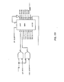
- FIG.3 depicts an overall block diagram of the bank controller 18 which interfaces between the system cache at the left hand side of the drawing and the memory modules at the right hand side thereof.
- Words which are read from the memory modules, identified as RD ⁇ -38, including 7 parity bits, are supplied to the bank controller for transfer to the system cache,.such words being identified as CRD ⁇ -31 in FIG 3, via the error correction logic 70 which also supplies four parity bits, identified as C R D P AR ⁇ -3.
- Address and data words which are to be written into the main memory modules are supplied from the system cache such words being identified as CA/WD 0-31, together with the parity bits therefor, identified as CA/WD PAR ⁇ -3, the data being supplied to the write data bus for the memory modules as WD ⁇ -31 and parity bits WD 32-38 via error correction logic 70.
- the addresses therefor are supplied in the form of information which is required to select the desired memory module (MODSEL 0-3) (to identify up to 16 modules) and to select the desired RAM within the selected module (ADDR ⁇ -7)
- the bank controller supplies the following control signals to the main memory which responds thereto as required.
- the R A S and CA S signals represent the row address and column address strobe signals for the RAM's of the main memory.
- the LDOUT signal causes the selected module to load its output register at the end of the current cycle and to enable the register to place the contents of the output register on the read data bus during the next cycle.
- the LDIN signal causes the selected module to accept data from the write bus during the next cycle and to write such data into the RAMs during the following cycle.
- the REFRESH signal overrides the module selection for the row address strobe (RAS) signal only. During a refresh operation one module is read normally and all.others perform an RAS refresh only.
- RAS row address strobe
- the bank controller also supplies the following control signals to the cache.
- the BC BUSY signal indicates that the bank controller is not able to accept a BC START (see below) request.
- the BC ERROR signal indicates that the data word placed on the read data bus during the last cycle contained a correctable error and must be replaced with the corrected word for the data which is on the bus during the current cycle. Once a BC ERROR signal has been asserted all subsequent words of the same block transfer are also passed through the error correction logic. Accordingly, BC ERROR need be asserted only once for each block transfer.
- the BC DATABACK signal indicates that the first word of the four word block to be transferred will be at the read data bus in the next cycle.
- the BC REJECT signal indicates that the bank controller cannot accept the contents of the write data bus at the end of the current cycle.
- the BC START indicates that a bank controller transfer operation is to commence.
- FIGS. 44-63 Specific logic diagrams for the particular units of the bank controller board 18 of FIG. 3 are shown in FIGS. 44-63, which latter figures are appropriately labelled as follows to show more specifically a particular embodiment of the various portions of the bank controller 18 depicted therein.
- the error correction logic 70 is shown in FIGS. 44-63 and includes the multiplexer store unit shown in FIG. 44; the C-bit generator unit 45; the (32 bits) register and (8 bits) register shown in FIG. 46: the drivers for the write data bus shown in FIG. 47; the S-bit generator shown in FIG. 48.
- the direct read driver unit is shown in FIG. 53.
- the R/W module selection unit and the RADDR and CADDR units are shown in FIG. 54; the MODSEL unit and drivers therefor are shown in FIG. 55; ' and the ADDRESS unit and driver therefor are shown in FIG. 56.
- FIGS. 57-59 Appropriate timing and control logic both for address and data transfer and for memory refresh operation is shown in FIGS. 57-59, the drivers for the principal control signals supplied to the memory module being shown in FIG. 60; and various bus interface logic as shown in FIGS. 61-63.
- FIG . 4 depicts the overall block diagram for a typical memory module of the main memory system of the invention and shows the memory array 60 of dynamic NMOS random access memories (RAM's) organized as four planes of 16K 39-bit words each and identifiable as planes ⁇ -3.
- a word which is to be written into the memory array is received from the bank controller as WD ⁇ -38 via buffer 62.
- Words being stored in even planes ⁇ and 2 are stored in even plane data register 63 while words to be stored in odd planes 1 and 3 are stored in odd plane data register 64.
- the control signals are supplied from the bank controller to control logic 65.
- the module select code bits MOD SEL ⁇ -3 are supplied to a comparator 66 to provide a MODSEL signal if the particular module has been selected.
- Control signals from control logic 65 are supplied to appropriate latching circuitry 67 to provide appropriate signals for controlling the operation of the memory array via drivers 61.
- the control signals from the memory bank controllers are first clocked into the plane ⁇ latching registers 67A and the outputs thereof drive the plane ⁇ RAMs via drivers 61A.
- the outputs of the first latch register are those clocked at a fixed time period later into the next latch register set 67B which drives the plane 1 RAMs.
- Such pipeline operation continues in order to drive the plane 2 and plane 3 RAMs such that all four RAM planes receive the same control signals at fixed intervals, resulting in the transfer of a block of four consecutive 39-bit words.
- RAM address from the bank controller includes eight bits, only seven bits of address are used for the 16K RAMs discussed above, the extra bit allowing for possible future expansion.
- addressed bits ADR 0-5 are clocked at fixed intervals to each of the latches 67A-67D of the planes ⁇ -3 at fixed intervals.
- ADR 6 is supplied to RAM selection logic 68 together with the plane 0 latch signal RPL 0 RAS to provide the J A DR 6 signal for the plane ⁇ latch register 67A.
- the RAS and CAS signals provide the necessary control signals via the control logic 65 and latch registers 67 for driving the row address strobe (RAS) and the column address strobe (C AS ) signals for the RAMs.
- RAS row address strobe
- C AS column address strobe
- the LDOUT signal to the input of control logic 65 causes the module to load its output register at the end of the current cycle and enable it onto the read data bus during the next cycle via the data out register and multiplexer logic 69 and read bus driver 69A.
- the LDIN signal at the input to control logic 65 causes the module to accept data from the write data bus via registers 63 and 64 for writing into the RAM during the following cycle.
- the following timing diagrams show the status of the various signals for block read and block write operations at each fixed time interval (in the particular embodiment described, for example, each cycle can be 110 ns). As can be seen, the plane ⁇ -3 data is provided in the read operation in sequence and the input data is written into such nlanes in sequence.
- FIGS. 64-78 More specific detailed logic circuitry for implementing the units shown in the block diagram of FIG. 4 to achieve the desired operation as described above are shown in FIGS. 64-78.
- Data in registers 63 and 64 are shown in FIGS. 64 and 65, respectively.
- the memory array 60 is shown in FIGS. 66-73 wherein plane ⁇ RAMs and the control input circuitry therefor are shown in FIGS. 66 and 67; plane 1 RAMs and the control input circuitry therefor are shown in FIGS. 68 and 69, plane 2 RAMs and the control input circuitry therefor are shown in FIGS. 70 and 71, and plane 3 RAMs and the control input circuitry therefor are shown in FIGS. 72 and 73.
- the data out register and multiplexer unit 69 are shown in FIG. 74.
- Latching and driver logic is shown in 75.
- the RAM select logic unit (RAMSEL LOGIC) is shown in FIG. 76, while the MODSEL comparator unit 66 and the various control logic units and latching circuitry associated therewith and with the input control signals from bank controller unit 18 are shown in FIG. 77.
- Memory module timing logic is shown in FIG. 78.
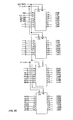
- the address translation unit (ATU) 14 is shown broadly in FIGS. 79-81, the primary function of such unit being to translate a user's logical address (L A ) into a corresponding physical address (PA) in the physical address space of the processor's memory modules discussed above.
- Such translation is effectively performed in two ways, one, by accessing a page from the system cache or from main memory at the particular page table entry specified in a field of the logical address and placing the accessed page in a translation store unit for use in performing the address translation, a sequence of operations normally designated as a Long Address Translation (LAT) and, the other, by accessing additional references to a page that has already been selected for access after an LAT has been performed and the page selected by the LAT is already present in the translation store.
- LAT Long Address Translation
- the latter translation provides an accelerated address reference and can be accomplished by saving, at the end of every Long Address Translation, the address of the physical page which has been accessed.
- the physical page involved is stored in a high speed random access memory (RAM) file designated in FIG. 79 at ATU translation store 100.
- RAM random access memory
- Translations of addresses on the physical page which is stored in the ATU translation store 100 are available to the processor within one operating time cycle of the CPU, while normally the Long Address Trnaslation will take a plurality of such cycles for a reference which requires a single level page table reference (e.g. 3 cycles) or a two-level page table reference (e.g. 5 cycles), where the page in question is available in the system cache memory. Even longer times may be required if the page involved can not be found in the system cache memory and must be accessed from main memory.
- a single level page table reference e.g. 3 cycles
- a two-level page table reference e.g. 5 cycles
- a secondary function of the ATU is to emulate all operations of the previous system of which the present system is an extension, e.g., in the system described, to perform all Eclipse memory management processor unit (MMPU1) address translation operations, as described in the above referenced publication for such systems, in an efficient and compatible way, such emulated operations being described in more detail later.
- MMPU1 Eclipse memory management processor unit
- logical word address (a byte address when shifted right by one position produces a word address)
- the segment and logical page address is 21 bits long, the segment and logical page address being divided into two fields, the Tag field and the Index field.
- the Tag field is defined as bits LA 2-14 while the Index field is defined as bit LA 1 plus bits LA 15-21.
- a logical word address LA ⁇ -31 is received from the arithmetic logic unit (ALU) on the logical address bus 26 it is latched into a logical address register (LAR) 101
- the Index bits LA 15-21 are taken directly from the logical address bus to address four RAM stores, the first being a Tag store 102, which retains the tag portions of the logical addresses corresponding to the physical addresses saved in the ATU physical address (PA) translation store 100.
- the Index bits LA 15-21 are also supplied to a validity store RAM unit 103 and to a protection store RAM unit 104, as discussed below.
- the physical address translation store 100 contains valid address translations, when a memory access is started the logical address is loaded into the logical address register 101 and the Index (bits LA 15-21) is used to select a location in the store.
- the address translation contained in the translation store 100 is the correct one and can be used to supply the desired physical address (signified by an ATU HIT signal at the output of comparator 105). If they do not match, a Long Address Translation operation must be performed to obtain the desired physical page address from the system cache or main memory. The physical page address which is thereby accessed by such LAT procedure to replace the physical page address previously contained in the ATU translation store 100 is placed on the appropriate transfer bus (CPM bus 20).
- the "tag" taken from the logical address register (LAR 2-14) is written into the tag store 102 at the location selected by the index and the physical page address from the memory data register 106 (MD 18-31) is written into the translation store 100 at the location specified by the index.
- the ATU configuration shown in FIG. 79 also contains further components which are used to place the translated physical address of a desired physical page table on the physical page address (PA) bus 27.
- PA physical page address
- HOPT high order page table
- LOPT low order page table
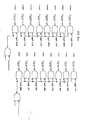
- Diagram A depicts a one-level- page table traversal
- Diagram B depicts a two-level page table traversal, the physical address bits 3-21 of the final physical address (i.e., the desired memory allocation data) being placed in the translation store 100 so that when the corresponding logical address is subsequently requires a translation, the physical address is available (an ATU HIT occurs) and there is no need for subsequent long address translation.
- the logical word address to be translated for a one-level page table translation has the format shown in Diagram A. Bits 1-3 of the word address specify one of the eight segment base registers (SBRs). The ATU uses the contents of this valid SBR to form the physical address of a page table entry (P TE ), as shown at point 1 of the diagram.
- SBRs segment base registers
- the selected S B R contains a bit (bit 1) which specifies whether the page table traversal is a one-level (bit 1 is zero) or a two-level (bit 1 is a one) page table.
- bit 1 a bit which specifies whether the page table traversal is a one-level (bit 1 is zero) or a two-level (bit 1 is a one) page table.
- Diagram A a page table entry address comprising the starting address of a selected page table and page table entry offset specifying a page address therein.
- the ATU begins with the physical address as shown at O2 of the diagram. This address becomes bits 3-21 of the PTE address. Bits 13-21 of the logical word address become bits 22-30 of the PTE address. The ATU appends a zero to the right of the PTE address, making a 29-bit word address.
- Bits 3-21 of the PTE address (unchanged in the step above) specify the starting address of a page table. Bits 22-31 of the PTE address specify an offset from the start of the table to some PTE (labelled PTEn in Diagram A). This PTE specifies the starting address of a page of memory, as shown at 3 of the diagram.
- PTEn bits 13-31, the page address become bits 3-21 of the physical address, as shown at 4 of Diagram A.
- the page offset field specified in bits 22-31 of the logical word address becomes bits 22-31 of the physical address. This is the physical word address translated from the original word address.
- the physical address bits 3-21 are placed in the translation store as the memory allocation data for subsequent use if the same logical word address requires subsequent translation. It should be noted that when using a one-level page table, bits 4-12 of the logical word address must be zero. If they are not zero and bit 1 of the SBR indicates a one-level page table is required, a page fault occurs.
- the processor produces a physical address.
- the logical word address to be translated has the format shown in the diagram, the steps (1) through (4) being substantially the same as in Diagram A except that bits 4-12 of the logical word address become bits 22-30 of the PTE address.
- the ATU appends a zero to the right of the PTE address, making a 29-bit word address.
- Bits 1-3 of the word address specify one of the eight segment base registers (SBRs).
- Bits 3-21 of the P TE address specify the starting address of a page table. Bits 22-31 of the PTE address specify an offset from the start of the table to some PTE (labelled PTEn). The PTE specifies the starting address of a page table. Thus, the ATU now constructs the address of a second PTE from the address at 4. The physical address specified in bits 13-31 of the first (PTEn) becomes bits 3-21 of the address of the second PTEm. Bits 13-21 of the logical word address become bits 22-30 of the second PTE's address. The ATU appends a zero to the right of the second PTE address to make a 29-bit word address.
- Bits 3-21 of the second PTE address specify the starting address of a second page table. Bits 22-31 of the second PTE address specify an offset from the start of the second table to some PTE (labelled PTEm in Diagram B). The second PTE specifies the starting address of a page, as shown at 5 in Diagram B.
- the second PTEm's bits 13-31, the page address become bits 3-21 of the physical address and the page offset specified in bits 22-31 of the logical word address becomes bits 22-31 of the physical address, as shown at 6 in Diagram B. This last value is the final physical word address.
- the physical page table address for the low order page table of a two-level page table is in bits 18-31 of the high order page table entry (HOPTE) which must be fetched from the main memory.
- HOPTE high order page table entry
- the second possible source of the physical page table address is the memory data register (MD) 105 which holds the data that arrives on the physical memory data (CPM) bus 20 as MD 18-31.
- a suitable page table multiplexer 107 is used to select which of the two sources will drive the physical address bus when its outputs are enabled.
- the third and final source is to drive the physical page address bus 27 directly through a physical mode buffer 108, such buffer being used to address physical memory directly (PHY 8-21) from buts LA 8-21 of the logical address bus.
- a physical mode buffer 108 such buffer being used to address physical memory directly (PHY 8-21) from buts LA 8-21 of the logical address bus.
- Such buffer is enabled while the ATU unit is turned off (i.e., no address translation is required) since the physical address in that mode is the same as the logical address and no translation is necessary.
- Bits PHY 22-31 of the physical address are offset by displacement bits, there being three possible origins for the offset.
- the first source of such offset is from bits LA 22-31 of the logical address bus which bits are used while in physical mode (no address translation is necessary) as well as the offset in the object page.
- the second source of the offset is bits LAR 4-12 (referred to as two-level page table bits in Diagram B above) of the logical address register which is used as an offset within the high order page table during a long address translation. Since this source is only nine bits long and page table entries are double words aligned on even word boundaries, a ten bit offset (to form PHY 22-31) is constructed by appending a zero bit to the least significant bit.
- the final source for the offset is bits LAR 13-21 (referred to as one-level page table bits in Diagram B above) of the logical address register which is used as an offset within the low order page table during a long address translation. A zero bit is appended to the least significant bit of this source also. Offset multiplexer 109 is used to select the desired one of such three offset sources. :
- the address bit sources for forming a low order or high order page table entry address in main memory in making a long address translation is formed from address fields in a segment- base register (SBR) and from address fields in the logical address register.
- SBR segment- base register
- the address fields of a segment base register can be depicted as follows:
- the SBR address field comprising bits 4-12 or the SBR address field comprising bits 13-21 is transferred to the memory data register 105 to form the higher order bits of the page table entry.
- the eight SBR registers are located in 8 of the 256 locations of scratch pad registers on the ATU. This use of such scratch pad locations for the segment base registers can be contrasted with prior known systems wherein the segment base register (or registers comparable thereto) in a segment, or ring, protection memory system are all located at specified locations in the main memory.
- V One of the bits of an SBR (identified above as "V” bit) is examined to determine whether the SBR contents are valid.
- L Another bit (identified above as “L” bit) is examined to determine whether a i-level or a 2-level page table entry is required so that the correct field is supplied to the memory data register.
- LEF Load Effective Address
- I/O Protect bit determines whether an I/O instruction can be permitted.
- the remaining field of the SBR contains the address offset bits.
- protection checks are made for each reference to memory, which protection checks are made by the use of protection store unit 104, protection logic unit 110 and ring protection logic unit 111 .for providing appropriate fault code bits (FLTCD ⁇ -3 which are supplied to the micro-sequencer (described below) via driver 112 on to the CPD bus 25 for initiating appropriate fault micro-code routines depending on which fault has occured.
- FLTCD ⁇ -3 fault code bits supplied to the micro-sequencer (described below) via driver 112 on to the CPD bus 25 for initiating appropriate fault micro-code routines depending on which fault has occured.
- a validity storage protection check determines whether the corresponding block of memory to which a memory reference is made has been allocated and is accessible to the current user of the system.
- the validity storage field is a one-bit field which is located, for example, at bit zero of each of the segment base registers (located on an ATU board as discussed above) or at bit zero in each of the high order page table entry addresses and low order page table entry addresses.
- a "1" indicates that the corresponding block has been so allocated and is accessible whereas a "0" indicates that the user cannot use such a memory block.
- the read protection field is a one-bit field normally located at a selected bit (bit 2, for example) in each of the low order page table entry addresses and a check thereof determines whether the corresponding object page can or cannot be read by the current user. If the page cannot be read, a read error is signaled by the fault code bits on the CPD bus. In a similar manner a check of the write protection error field determines whether the corresponding object page can be written into by the current user, an appropriate write error being signaled by the fault code bits if the user attempts to write into a page to which he is not allowed.
- the execute protection field is a one-bit field which is located at a selected bit (e.g. bit 4) in each of the low order page table entry addresses and a check thereof determines whether instructions from a corresponding object page can or cannot be executed by the current user. If such an instruction fetch is not allowed, an execute error is signaled by the fault code bits on the CPD bus. Execute protection is normally checked only during the first fetch within a page and any additional instruction fetches are performed using the physical page address from the first fetch, which for such purpose is retained by the instruction processor.
- the system will abort the operation if a chain of more than a selected number of said indirect addresses is encountered. For example, in the system under discussion if a chain of more than sixteen indirect addresses is encountered the operation is appropriately aborted and a defer error is signaled by the fault code bits on the CPD bus.
- Such protection is utilized, for example, normally when the system has performed a loop operation and the system, because of a fault in the operation thereof, continues to repeat the indirect loop addressing process without being able to break free from the loop operation.
- Ring maximization protection is utilized when the user is attempting to reference a logical location in memory in a lower ring.(segment) than the current ring of execution (CRE 1-3). Since such operation is not permitted by the system, the operation must be aborted if the user attempts to reference a lower ring than currently being used and a ring maximization error is signaled on the CPD bus. Since the logical address space is divided into eight rings, or segments, a ring which the user desires to reference can be indicated by bits 1-3, for example, of the logical address.
- FIGS. 80 and 81 The specific logic circuitry utilized for such protection checks (i.e., the protection store 104 and the protection loqic 110 and the protection loqic 111 associated therewith) is shown in FIGS. 80 and 81.
- loqic for the qeneration of the read error, write error, execution error and validity error signals is shown in FIG.80 and logic for generating the defer error and ring maximization error signals being shown in FIG. 81.
- the access field in a page table entry comprises three bits (MD 2-4) is shown in FIG. 79 and indicates the capabilities of the referenced data item in the logical address space, i.e. as to whether the reference data item is to be a read access, a write access, or an execute access, the protection store 104 responding to such bits to produce either a read enable signal (RD ENB), or a write enable (WR ENB) or an execute enable (EX ENB) .
- the ring protection governs the proper interpretation of the access privileges of the user to a particular ring, a user being permitted access only to selected, consecutively numbered rings. Thus, access can only be made to a bracket of rings (an access bracket) if the effective source for such reference is within the appropriate access bracket.
- the read bracket of a data reference in any ring is the ring number. That is, a data address reference to segment 5 (ring 5), for example, can never legitimately originate from an effective source which is greater than 5. In other words an effective source in segment 5 can never reference a ring lower than ring 5 and, therefore, if a reference from an effective source greater than 5 attempts to access ring 5 a ring maximum error (MAX ERR) will be signaled as shown by the logic in FIG. 13.
- MAX ERR ring maximum error
- the ring maximization function is used to determine whether or not the reference is a valid ring reference and, if it is, the page table entry that references the address datum is examined to see if the page is a valid one. Then, if the read protection bit indicates that such valid page can be read, the read can be performed. If any one of the examinations shows a protection error (i.e., ring maximization error, validity error, or read error) the read is aborted and an appropriate fault code routine is called. Similarly, appropriate examination for protection errors for write access and execute access situations can also be performed.
- a protection error i.e., ring maximization error, validity error, or read error
- Any ring crossing attempts occur only as a result of an explicit attempt to do so by a program control instruction, and such explicit attempt can occur only if the following conditions are satisfied.
- the return address for outward returns is merely interpreted as a normal word address.
- the branch address is interpreted as follows: Bits 16-31 are interpreted as a "gate" into the specified segment (SBR of bits 1-3) in the target space. The gate number is used to verify that the specified gate is in the called segment and, upon verification, to associate on instruction address with the specified gate via a "gate array" in the called segment, as discussed below.
- the location of the gate array in any called segment is indicated by a pointer contained in particular locations of the 'called segment (e.g., in a particular embodiment the pointer locations may be specified as locations 34 and 35 in each segment.
- the structure of the gate array is as follows:
- the gate number of the pointer which referenced the target segment is compared with bits 16-31 of the first 32 bits of the gate array. If the gate number is greater than or equal to the maximum number of gates in the gate array, the ring crossing call is not permitted and a protection' fault occurs (if the maximum number of gares is 0, the segment involved cannot be a valid target of an inward ring crossing call operation).
- the gate number is then used to index into one of the gates of the gate array which follows the first 32 bits thereof.
- the contents of the indexed gate are read and are used to control two actions.
- the effective source is compared to the gate bracket bits 1-3 of the indexed gate.
- the effective source must be less than or equal to the referenced gate bits and, if so, the P C offset bits 4-31 become the least significant 28 bits of the program counter and bits 1-3 of the program counter are set to the segment containing the gate array.
- the gate in a ring crossing operation is a permitted entry point to the ring to which the crossing is made, a new stack is constructed. In order to do so a stack switching operation must occur since there is only one stack per ring. Thus, before the new stack can be created, the contents of the current stack management registers must be saved at specified memory locations of the caller's ring.
- the callee's stack can then be created, the arguments from the caller's stack being copied onto the newly created callee's stack, the number of such arguments being specified by the X or the LCALL instruction (see Appendix B). An appropriate check is first made to determine whether copying of all of the arguments would created a stack overflow condition. If so, a stack fault is signalled, the ring crossing being permitted and the fault being processed in the called ring.
- emulation control logic unit 115 which, in response to ; coded instructions generated by the microsequencer board 13 produces such signals to permit operation for 16-bit addresses equivalent to the memory management protection unit (MMPU) of ECLIPSE comparators as described in the aforesaid publications thereon.
- MMPU memory management protection unit
- FIGS. 82-100 Specific logic circuitry for implementing the various ) blocks of the address translation unit shown in FIGS. 79-81 are shown in FIGS. 82-100.
- FIG. 82 depicts the translation store unit 100 supplied with bits MD 18-31 from the memory data register; 105 and in turn supplying the translated physical address bits i 8-21 which have resulted from a translation of the logical address 3 bits LA 15-21.
- FIG. 82 also shows the page table address multiplexer unit 107 and physical mode buffer unit 108.
- such figure includes the "last block" register unit 116 which during an ECLIPSE MMPU emulation operation provides the physical address bits PHY 8-21.
- FIG. 82 also shows the LMP Data Register.
- FIG. 83 shows Tag Store 102 and Protection Store 104.
- FIG. 84 shows the logical address reqister 101, while physical address offset multiplexer 109 and the logical address register CPD bus driver unit are shown in FIGS. 86 and 87, respectively.
- the physical address bus driver units for filing the appropriate physical address bit PHY 8-21 are shown in FIG. 88.
- Protection logic including fault detection and cache block crossing trap logic is depicted in FIGS. 89-92, protection logic identification encoder unit 110 being shown in FIG. 89, the fault code bit drive unit 112 being shown in FIG. 90, ring protection logic circuit 111 being shown in FIG. 91 and the fault detection and cache block crossing logic being shown in FIGS. 92 and 93.
- Validity store unit 103 is shown in FIG. 94 together with translation purge logic and the multiplexer associated therewith.
- the translation register of FIG. 79 is depicted in detail in FIG. 95.
- the reference/modify storage and control logic unit is shown in FIG. 96, the state save drive unit associated therewith being depicted in FIG. 97.
- the 16 bit MMPU emulation control logic is shown in FIG. 98.
- ATU timing logic is shown in FIG. 99 and suitable system code interface logic is shown in FIG. 100.
- the instruction processor (IP) 12 is utilized to handle the fetching and decoding of macro-instructions for the data processing system of the invention.
- the instruction processor operates both at and ahead of the program counter and its primary function is to provide a starting microaddress (STpAD) for each micro-instruction, which starting microaddress is supplied to the microsequencer unit 13.
- STpAD starting microaddress
- Subsidiary functions of the instruction processor are (1) to provide the source and destination accumulator designations, (2) to provide the effective address calculation parameters for the arithmetic logic unit and (3) to provide sign or zero extended displacements for making memory references or for in-line literals (immediates) to the arithmetic logic unit (ALU).
- the instruction processor includes instruction cache logic 120 (ICACHE), macro-instruction decoding logic 121 (which includes an instruction decode register as shown in FIG. 103) and program counter/displacement logic 122 as described below.
- The.ICACHE logic functions as a pre-fetcher unit, i.e., the instruction cache (ICACHE) thereof obtains a : block of subsequent macro-instructions for decoding, which block has been accessed from memory while the previous macro-instructions are being executed.
- the ICACHE stores the subsequent block of macro-instructions even if such macro-instructions are not : immediately going to be used by the microsequencer.
- the decoding logic 121 of the instruction processor responds to a macro-instruction from ICACHE, decodes the operational code thereof (opcode) to provide the opcode description information for control and status logic 123 and to supply the information needed therefrom to the starting micro-address (STuAD) register 124 (and thence to the micro-sequencer) to identify the starting micro-address of the required micro- instructions.
- opcode operational code thereof
- the displacement logic 122 supplies the displacement data to the ALU if the index for such displacement is on the ALU board. If the index for the displacement is the IP program counter, the displacement logic combines the displacement information with the program counter information available at the instruction processor to form the logical address for supply to the LA bus.
- a macro-instruction is read from an ICACHE storage unit of the ICACHE logic 120 into the decode logic 121 which thereupon decodes the instruction opcode and generates the starting micro-address for the micro-sequencer.
- the instruction processor simultaneously reads the next macro-instruction from the ICACHE into the decode logic.
- the decode logic is decoding the next macro-instruction for generating the next starting micro-address.
- the micro-sequencer reads the next micro-instruction from the next starting micro-address. Accordingly, a pipeline decoding and execution process occurs.
- the ICACHE logic 120 includes an ICAC HE data store unit 130, a tag store unit 131 and a validity store unit 132.
- the operation of the ICACHE is substantially similar in that the tag portion (PHY ICP 8-21) of the address of each desired word of the macro-instruction is compared at comparator 133 with the tag portions of the addresses stored in the TAG store 131 of those words which are stored in the ICACHE data store 130.
- the validity store unit demonstrates whether the desired address . is a valid one. If the address is valid and if a tag "match" occurs, the 32-bit double word at such address is then supplied from the ICACHE data store 130 to the decode logic 121.
- ICACHE block memory reference may be to the system cache (SYS CACHE) or to the main memory, if the system cache access also misses.
- the desired macro instructions thereof are written into the ICACHE data store 130 from CPM register 134 and the block is simultaneously routed directly into the decoding logic through bypass path 135.
- the ICACHE logic can then continue to prefetch the rest of the macro-instructions from the fetched page as an instruction block thereof, placing each one into the ICACHE data store 130 as they are accessed.
- the control logic for the ICACHE logic 120 is ICACHE/ICP control logic unit 136.
- the decode logic includes instruction decode units 140 and 141 for decoding the opcode portion of the macro-instructions.
- Decode unit 140 is used for decoding the opcodes of the original basic instructions for the system of which the present system is an extension.
- basic instructions may be the NOVA and ECLIPSE instructions for Data General Corporation's previous NOVA and ECLIPSE system.
- Decode unit 141 is used for decoding the opcodes of the extended instruction set,e.g. the "Eagle" macro-instructions mentioned above.
- the opcodes are supplied from an instruction decode register (IDR) 142 having three storage register sections, each capable of storing a word and identified as IDR A, IDR B and IDR C.
- the opcode of each macro-instruction is stored in the IDR A section while displacements are stored in the IDR B and C sections.
- An IDR shifter unit 143 is used to shift the desired opcode portion of the instruction accessed from the ICACHE data store 130 into the IDR A section of IDR 142 and to shift the appropriate displacement words of the instruction, if any, to the IDR B and IDR C sections thereof.
- the control logic for the IDR and the IDR shifter units is IDR/shifter control unit 137, shown in FIG.102.
- the decode units 140 or 141 When the macro-instruction has been routed to the decode logic, the decode units 140 or 141, as required, decode the opcode portion thereof to provide opcode description (OPCD DSCR) information, including the length of the instruction (i.e., whether the instruction comprises a single, or double or triple word).
- OPCD DSCR opcode description
- the entire instruction has been supplied to the decode logic (from ICACHE data store 130) a SET IDR VLD signal is generated to produce an IDR VLD signal at IDR/shifter control 137 (FIG.102).
- the starting micro-address is loaded into the ST ⁇ AD register 144 from either decode PROM 140 or 141 depending on whether the macro-instruction is a basic or an extended instruction. Control of the loading of STpAD register 64 resides in ST U AD load control unit 145.
- the displacement word or words, if any, are generally' present in IDR B or C (for certain NOVA instructions a byte displacement may be extracted from IDRA, although generally for almost all other instructions displacements are extracted from IDRB and IDR), being extracted from the displacement logic 146, as shown in FIG.104.
- the displacements are sign or zero extended, as necessary, and are clocked into a displacement register thereof so as to be made available either directly to the logical address (LA) bus or to the CPD bus for use at the ALU unit, as discussed below.
- an UPDATE signal is issued by the IP status logic unit 138 (FIG.102) to inform the IDR/shifter control 143 that the decoded information has been used and can be shifted out of IDR 140/141.
- the decoding of subsequent macro- instructions continues until a discontinuity in the straight- line decoding operation occurs.
- the micro-sequencer issues an IPSTRT signal to the program counter register 147 of the instruction processor (FIG. 20) so that a new program counter address (LA 4-31) can be placed in the program counter register from the logical address bus.
- the starting micro-address register 144 is reset and the starting micro-address of an appropriate wait routine, for example, is placed therein until.the decoding process for the instruction associated with the new program counter can begin.
- the sequence of macro-instructions which are being decoded are present on more than one physical page.
- a special routine must be invoked in order to fetch the next page into the ICACHE store 130 so as to continue the prefetching operation on the new page.
- the starting micro-address register is loaded with the starting micro-address of a suitable page control routine which accesses the required new page and permits the next page to be loaded into ICACHE store 130 via physical page register 134 so that the instruction processor can continue with the decoding of the macro-instructions thereon.
- the correct page must be accesssd from either the system cache or main memory because of an ICACHE "miss" in the instruction processor.
- Access to the system cache is provided at the same system cache input port as that used by the address translation unit (ATU).
- ATU address translation unit
- the I C A CHE is given a lower priority than the ATU so that if the ATU wishes to access the system cache the instruction processor must hold its access request until the ATU has completed its access.
- ICACHE logic as described herein becomes extremely advantageous in programs which utilize a short branch backwards. If a macro-instruction branch displacement is less than the number of words in the ICACHE data store there is a good chance that the required macro-instructions will still be stored locally in the ICACHE data store and no additional system cache or main memory references are required.
- the overall ICACHE logic 120 may comprise a single set, direct mapped array of 256 double words in data store 130 plus Tag and Validity bits in Tag Store 131 and Validity Store 132.Data is entered into the data store as aligned double words and the ICACHE data store is addressed with the eight bits which include bits ICP 23-27 from the instruction cache pointer (ICP) unit 150 shown in FIG.105 and bits ADR 28,29,30 from unit 139.
- ICP instruction cache pointer
- a copy of the Tag store 131 of the instructor processor's ICACHE unit is also kept in the system cache, the latter cache needing such information so that it can inform the instruction processor when data has been written into the ICACHE.
- the validity store 132 is arranged, for example, in a particular embodiment, as 64 double words by four validity bits in order to indicate the validity of each double word in the I CAC HE data store.
- Each initial fetch into a new block of instruction words will set the corresponding validity bit for the double words and reset the remaining three validity bits.
- the corresponding validity bit for the prefetch double word is set while the remaining three validity bits remain the same. The prefetching operation stops when the last double word in the block has been prefetched in order to avoid unnecessary system cache faults.
- the ICACHE control logic unit 136 (FIG.102) asserts a signal (identified as the ICAT signal) which is supplied to the ST ⁇ AD load control logic 145 (FIG.103)
- the STpAD control logic 145 supplies the starting micro-address for the ICAT micro-code routine which thereupon performs the necessary address translation operation for a transfer of the next physical page address for the ICACHE data store 130.
- the instruction processor utilizes two pointers to the instruction stream.
- the first pointer is the program counter register 147 (FIG.104) which holds the logical address of the instruction which is being executed, and the second pointer is the instruction cache pointer (ICP) 150 (FIG.106) which holds the logical address of the next macro-instruction which is needed for the decode logic.
- ICP instruction cache pointer
- a separate register PICP 152 (physical instruction cache pointer) holds the physical page address of the logical page referred to by bits 4-21 of the instruction cache pointer (ICP).
- ICP 150 functions as the prefetch logical address pointer
- the PICP functions as the prefetch physical address pointer.
- the program counter 147 and the ICP 150 are loaded from the logical address bus at the start of an instruction processor operation.
- the ICP is incremented ahead of the program counter as the decoding pipe- line operation is filled.
- the . PICP physical address is used to reference the memory and the ICP address is used as a pointer to the next logical page address for address translations when the end of the correct page has been reached.
- the optimum performance is achieved when the instructions are locally available in the ICACHE, such instructions thereby becoming substantially immediately available when the micro- sequencer requests them. Instructions which are not locally available in the ICACHE take an amount of time which is dependent on system cache access operation and page fault routine operations.
- the macro-instruction decoding logic utilizes three 16-bit fields identified as the IDR A, IDR B, and IDR C fields, as mentioned above.
- the "A” field contains the opcode while the "B” and “C” contain either the displacement(s) for the instruction in the "A” field or one or more fields of the macro-instruction which follows in the instruction stream.
- the instruction decode register, IDR 142 is arranged to keep all three fields full, if possible, by sending word requests tothe ICACHE (ICP control unit 136) when any of the three ID R fields is empty. As mentioned above, if the ICACHE word request results in an ICACHE "miss" a system cache fetch is initiated.
- the "A” field of the instruction decode register 142 is used by the decode logic PROMs 140 or 141 to decode the opcode of the macro-instruction and, also to provide the starting address of the macro-instruction which is required.
- the "B” and “C” fields determine the displacements, if any, that are required. Each field is one word in length and therefore the longest instruction that the instruction processor can decode and canonicalize the displacement for has a maximum length of three words.
- the decode PROMs 140 or 141 decode the opcode of the instruction. If the entire instruction, including opcode plus displacement, is in the instruction decode register, a signal IDR VLD is asserted by the IDR shifter control logic 137 to inform the IP status logic 138 that an entire instruction is ready to be decoded so as to provide a starting micro-address for ST P AD register 144.
- the displacement logic 146 which extracts the displacement, either sign or zero extends it, as necessary, and then loads it into a displacement register. If the displacement index is on the ALU board the displacement is latched onto the CPD bus via latch unit 153 for supply thereto. If the displacement index is the PC register 147, the displacement is added to the PC bits at adder 148 and supplied to the logical address bus via latches 149 : as shown in FIG.104.
- the instruction decode register 142 is shifted by the length of the instruction that has been decoded so as to be ready to receive the next instruction, i.e., a shift of one, two or three words.
- the IDR shifter unit 143 serves to provide such shift of the contents of the instruction decode register 142.
- a shift of three words for example, completely empties the instruction decode register which is then ready to receive the next instruction from the ICACHE (or directly from memory on an ICACHE "miss").
- the shifter for example, allows either word in a double-word instruction which has been accessed from the ICACHE to be directly loaded anywhere into the instruction decode register.
- the placement in IDR 142 is determined by examination of the validity bits in the IDR.
- the double word would be loaded into two empty
- the ICACHE pointer 150 would be incremented so that it points to the next double word. If the IDR has only one empty field and a word pointer points to an even double word, then the first word would be loaded into the IDR and the word pointer would be sent to point to the second word of the double word and the ICACHE pointer remains the same. When the word pointer points to the second word, only one word can be accessed from the ICACHE and loaded into the instruction decode register.
- the decode logic utilizes predecode logic 154 (FIG.103) which is used to select the location in one of the two sets of decode PROMs 140 and 141.
- predecode logic 154 FPGA/ECLIPSE instructions
- the second set of PROMs 141 holds the extended instructions (e.g., EAGLE instructions).
- the decoding process for the basic set of decode PROMs 140 is performed in two stages, the first level being performed in the predecode logic 154 at the output of the shifter which is used to place the basic macro-instructions into the correct form so that the decode logic 140 can decode the opcode and be ready with the displacement information in the correct form and sequence.
- each incoming macro-instruction maps into at least one location of a selected one of the decode PROMs 140 or 141 to produce the required opcode descriptors and the required starting micro-address for supply to the micro-sequencer.
- decode PROM 140 e.g., NOVA/ECLIPSE
- decode PROM 141 e.g., EAGLE
- selected bits e.g., bits ⁇ , 12-15 as discussed above
- the selection of the decode PROM is not determined by a separately designated "mode" bit as in previous systems, which prior process causes the decode operation to be mutually exclusive.
- the present system in selecting the appropriate decode operation performs such operation on an instruction by instruction basis since each instruction inherently carries with it the information required to determine such decode selection.
- FIGS. 107-136 Specific logic circuitry for implementing the block diagram of the instruction processor to provide the operation discussed above with reference to FIGS. 101-106 is shown in FIGS. 107-136.
- ICACHE data store 130 and the ICACHE data store address input logic are shown in FIGS. 107 and 108, respectively, while CPM register 134 supplying cache block words from memory being shown in FIG. 109 and 109A.
- ICACHE tag store 131 is also depicted in FIG. 109B and 109C and ICACHE validity store 132, together with the validity store address input is shown in FIGS. 110 and 111, respectively.
- Comparator 133 and logic for providing the SET IDR VLD signal are shown in FIG.112.
- FIG. 113 shows IDR shifter 143, the IDR shifter control logic 137 being shown in FI G. 114.
- the instruction decode register (IDR) unit 142 is depicted in FIG. 115 and include IDR sections A, B and C as shown.
- the ICACHE pointer (ICP) logic 150 and the ICP logical address driver logic of FIG. 106 is shown in more detail in FIGS. 116 and 117, respectively.
- the ICACHE pointer pre-fetch request control logic 151 and the physical ICP translation register 152 of FIG. 105 is depicted in more detail in FIGS. 118 and 119, respectively.
- Other general ICACHE control logic is further depicted in FIG. 120.
- the driver logic which provides inputs FASA ⁇ -15 from the CPD bus to IDR A as shown in FIG. 103 is depicted in FIG. 121, while the instruction pre-deccde logic and control therefor is shown in FIG. 122.
- Decode PROMS 140 and 141 which effectively include the ST ⁇ AD register 144, together with the IP status logic 138'are shown in FIG. 123.
- the starting microaddress control logic 145 is depicted in detail in FIG. 124.
- the displacement logic 146 is shown in FIG. 125, the displacement multiplexer associated therewith being depicted in FIG. 126.
- the sign extend (SEX) logic is shown in FIG. 127, while the zero/ones extend logic is shown in FIG. 128.
- FIG. 129 shows the displacement increment buffer of FIG. 104 while the displacement latch and drivers 153 are depicted in FIG. 130.
- FIG. 131 shows program counter register 147 and the CPD bus driver of FIG. 104, while adder 148 and the P C + DISP latch and driver units 149 are shown in FIGS. 132 and 133, respectively.
- Program counter clock logic is depicted in FIG. 134.
- FIG. 135 General instruction processor timing and control logic circuitry is shown in FIG. 135, while the system cache interface logic required for the instruction processor 12 to interface the system cache 17 is shown in FIG. 136.
- the primary function of the micro-sequencer unit is to generate micro-instructions from the starting micro-address which is supplied to a random-access-memory (RAM) storage unit on the micro-sequencer board.
- RAM random-access-memory
- FIGS. 137-138 An overall block diagram of the micro-sequencer board for the particular embodiment of the system of the invention described herein is shown in FIGS. 137-138.
- the RAM storage unit is identified as the micro-control store unit 170 and is capable of storing up to 4-K 80 bit (79 bits plus 1 parity bit) micro instructions and is sufficient to store all of the micro-instructions required for the system being described.
- the micro-instructions can be appropriately loaded into store unit 170 initially (i.e., prior to the use of the system) through a suitable console via appropriate console interface logic unit 171. Once the entire micro-instruction set has been loaded into the micro-control store unit 170, the console interface logic need no longer be used, unless a micro-instruction is changed or additional micro-instructions are to be stored. Addresses for the micro- instructions are supplied at the RA input to the micro-sequencer board.
- the system is ready for performing the micro-instructions, as determined by the instruction processor unit 12 which, as discussed above, supplies the starting micro-address (STpAD) for a micro- instruction routine.
- STpAD starting micro-address
- ST ⁇ AD starting micro-address
- the starting micro-address selects the starting micro-instruction at the appropriate location in the micro-control store and supplies the control signals associated with said instruction via buffer 174 to the appropriate locations within the overall data processing system which are involved in the operations required for such instruction in a manner similar to that which would occur in supplying instructions to any data processing system.
- the micro-sequencer must then determine the next addres's required for the next sequential micro-instruction (if any) via appropriate decoding of the "next address control" field (NACO-19) of the current micro-instruction.
- This field in the particular embodiment described is a 20-bit field of the 80-bit micro-instruction obtained from the micro-control store.
- the NAC field is suitably decoded by the NAC decode logic 175 to provide the necessary control signals (some of which are identified) required to obtain the next micro-address.
- the 'decoding process can in one mode be a conditional one, i.e., wherein the NAC field decoding is conditioned upon one of a plurality of possible conditions which must be appropriately tested to determine which, if any, condition is TRUE.
- the NAC field decoding is conditioned upon one of a plurality of possible conditions which must be appropriately tested to determine which, if any, condition is TRUE.
- the selection of the next micro-address may not be conditioned on any of the 64 conditions involved.
- the address is selected from one of four sources, as determined by the decoding and condition test logic 1 8 2, for supply to the micro-control store 170 via ADDR multiplexer unit 176.
- Decoding and condition test logic 182 is shown in further detail in FIG. 138.
- the address multiplexer output can be selected from the next sequential program counter address(pPC 4-15) which represents the previous micro-address incremented by one as obtained from the(uPC +1) unit 177 and increment logic 178 which accepts the previous micro-instruction (RA 4-15), increments it by one and supplies it to an input of the address multiplexer unit 176.
- next micro-address may be obtained from a temporary storage of a plurality of micro-addresses for a particular micro-code routine which addresses have been stored in a stack RAM storage unit 179, the next address being supplied directly as the address at the top of the stack (TOS 4-15) via a top of the stack (TOS) register 180.
- the address at the top of the stack may already have been accessed (popped) from the stack and saved in a previous operation in the Save TOS register 181 (particularly used in restoring the overall context after an interrupt process) so that the next micro-instruction address may alternatively be obtained -from the top of the stack data (STOS 4-15) which has previously been saved in the STOS register.
- a further source of the.next micro-address for the address multiplexer may be an absolute address from decode and condition test logic 182, shown more specifically in FIG.138, which address is specified by the micro-instruction word itself or an absolute address which may be identified by bits from another source external to the micro-sequencer board which other sources dispatch such address to the micro-sequencer, i.e., from the address translation unit (ATU) or from the arithmetic logic unit (ALU) selected bits of which can be suitably concatenated with absolute address bits from the current micro-instruction to form the next micro-address. As see in FIG. 138, the latter bits may be received via suitable registers 183 and 184 (see FIG.
- Such bits can be concatenated with bits from the micro-instruction itself, identified by NAC bits ⁇ -2, 8-19, to form five possible micro- addresses by concatenation logic unit 185.
- One of five concatenated addresses is capable of being selected at Dispatch Multiplexer unit 186 and thereupon supplied to Address Multiplexer 176.
- stack pointer logic 187 and stack control logic 188 are used with the stack RAM unit 179.
- the stack addresses which are supplied via stack pointer logic 187 determine the locations of the sequence of micro-instruction addresses which are required for micro-code routines, which sequence has been previously supplied to the stack via stack multiplexer unit 189, the inputs of which are obtained either as absolute addresses (AA 4-15) from the micro-instruction which is currently being processed or as addresses obtained from the micro-program counter 177 ( ⁇ PC + 1), from a dispatched ALU source (CPD 20-31) via the CPD bus, or from an address which has been previously saved (AD 4-15) in save register 190.
- conditional jump instruction CJMP
- the address of the next micro-instruction is to be supplied either as an absolute address from the dispatch multiplexer to which the micro- program must jump if the condition is TRUE or as the next sequential program address from the micro-program counter ( FC+1) if the condition is not TRUE.
- the present micro-address is at a selected location of the ⁇ -control store 170 (e.g.
- next micro-address is to be either the location signified by the next sequential program counter address (e.g., location "101") if the condition is not TRUE, or a jump to specified absolute address (e.g., at location "500") if the condition is TRUE.
- the micro-sequencer In order for the micro-sequencer to determine which of the two locations is be be selected, i.e., the absolute address (AAD 4-15) or the micro-program counter address ( ⁇ PC 4-15), the conditon must be tested to determine if it is "TRUE".
- the absolute address (AAD 4-15) will be selected as the correct address from address multiplexer 176, while if the condition is not TRUE, the next micro-program counter address ( ⁇ PC 4-15) will be selected.
- the testing logic 198 is shown in FIG. 138.
- FIGS. 139-153 Specific logic circuitry for implementing the micro- sequencer unit 13 as discussed above and shown in the block diagrams of FIGS. 137 and 138 are shown in FIGS. 139-153.
- Stack logic circuits including the stack ram 179, the stack multiplexer 189, the stack pointer unit 187 and the top-of-stack unit 180, are specifically shown in FIG. 139.
- the save-top-of-stack unit 181 is shown in FIG. 140.
- Address multiplexer 176 is depicted in FIG. 141, while the address save register is shown in FIG. 142 and the address logic 173 for supplying addresses to the microcontrol store 170 is shown in FIG. 143.
- FIG 144 depicts the.starting microaddress (ST ⁇ AD) driver unit 172.
- the imcremented microprogram counter (pPC+l) unit 177 and increment unit 178 are shown in FIG. 145.
- Microcontrol store 170 is specifically depicted in FIG. 146 * and the next address control (NAC) decode logic circuitry 175 is specifically shown in FIG. 147. Parity logic is shown in FIG. 148.
- NAC next address control
- FIGS. 149-153 specific logic circuitry for implementing such circuitry is shown in FIGS. 149-153.
- concatenation logic 185 and dispatch multiplexer 186 are depicted in FIG. 149
- CPD multiplexer 197 is shown in FIG. 150
- 6-bit counter 196 is shown in FIG. 151
- 8 flags unit 193 is shown in FIG. 152
- test ⁇ and test 1 multiplexers 194 together with condition multiplexer 195 and the condition output unit 192 are all shown in FIG. 153.
- FIG.153 shows a block diagram of a typical arithmetic logic unit generally having a configuration known to those in the art.
- the ALU unit 200 which performs the arithmetic and logical operations, has two inputs, identified as inputs Rand S, which are supplied from a pair of multiplexers 201 and 202, respectively.
- the inputs to multiplexer 202 are obtained from the A and B outputs of a register file 203.
- a third input may be obtained from a source which supplies zeros to the multiplexer at all 31 bit positions (identified as the " ⁇ " input) and a fourth input may be obtained from Q register 204.
- Register file 203 contains 16 and 32 bit registers and includes four fixed point registers (ACC ⁇ -3), four floating point registers (FPAC ⁇ -3) , and eight general registers (GR ⁇ -7) .
- the selection of the appropriate registers for supplying the A and B inputs to ALU 200 is determined by the AREG ⁇ -3 and BREGO-3 bits of the micro-instruction field, as discussed in more detail below.
- the inputs to multiplexer 201 are obtained from the A output of the register file, from the D-bus 205 or from an all zeros input, as discussed with reference to multiplexer 202.
- the output of ALU 200 is supplied to a multiplexer 206 which selects either the output from ALU 200 or an output directly supplied from the A terminal of register file 203.
- the output of multiplexer 206 can be supplied to the logical address bus if the calculation is an address calculation, to the register file 203 for writing back into a selected register therein, to Q register 204 or to a plurality of other units on the arithmetic logic board, significant exemplary ones of which are identified as shifter units 207, a data store register 208 or directly to the D-bus 205 or to the memory data bus.
- the shifter outputs are supplied to the D-bus, while the data store register 208 supplies data to the CPD bus or to the D-bus via CPD register 209. Data supplied to the D-bus can then be used in subsequent arithmetic or logic operations via multiplexer 201. Other sources of the system may also supply data to D-bus 205, if desired.
- the general configuration of the arithmetic logic unit board 11, as shown in Fig.154, is helpful in understanding the micro-instructions which are discussed below.
- the micro-control store 170 thereof supplies a micro- instruction of 80 bits, the format thereof being depicted below.
- the overall format comprises eighteen fields, one field of which has five bits available as reserve bits for future use.
- the seventeen fields which are utilized are described below.
- the first 20 bits of the micro-instruction format comprise the field for controlling the selection of the address for the next micro-instruction which address is either a "conditional" -address, i.e. an address the selection of which is dependent on whether a specified condition which is tested is either true or false, or an "unconditional" address, i.e., an address which is selected independently of any conditions.
- the NAC field of the micro-instruction for selecting a conditional address carries with it a 6 bit test field which identifies which of up to 64 conditions must be tested to determine whether a specified condition is true or false.
- the basic format of the NAC field for selecting a conditional address is shown below:
- the conditions which can be tested may relate to conditions with respect to operations of the arithmetic logic unit, the address translation unit, the instruction processor, the micro-sequencer unit itself or input/output (I/O) conditions. ;
- I/O input/output
- Appendix C lists 53 conditions which can be tested in the particular system design described herein, involving tests relevant to the ALU, ATU, IP and micro- sequencer units, as well as certain I/O tests.
- conditional addresses may be selected as discussed below, it being helpful to consider the following discussion in conjunction with FIGS. 33 and 34 showing broad block designs of the micro-sequencer logic.
- a first conditional address may be a conditional absolute address, i.e. an address which uses absolute address bits AA 4-15 appropriately selected and supplied by dispatch multiplexer 186 to the address multiplexer 176, as seen ,in FIG. 4.
- conditional absolute address utilizes the same format shown above for the mode bits, polarity bit and test bits, with the 10 absolute address bits being extended to a full 12 bits by concatenating the most significant bits of the current micro-program counter as the first two bits thereof (sometimes termed the "page bits").
- the conditional absolute address may be utilized in 5 different modes as set forth in Appendix D (see”Absolute Address Conditional” therein) .
- An example one mode such as a "Conditional Jump Code” (CJMP) can be illustrated below.
- conditional address is a conditional dispatch address, wherein a portion of the address bits are obtained (or dispatched) from sources external to the micro-sequencer unit (such as the arithmetic logic unit or the address translation unit, for example) which dispatch bits can be concatenated with some or all first eight absolute address bits (AA ⁇ -7) as shown in FIG.34.
- the micro-sequencer unit such as the arithmetic logic unit or the address translation unit, for example
- AA ⁇ -7 first eight absolute address bits
- the source from which the dispatch bits are obtained are identified by the two DSRC bits for 4 different source identifications.
- the address may be formed by direct replacement of the lower 8 bits of the formed absolute address with the lower 8 bits of the CPD bus as shown below.
- the address may be formed by direct replacement of the lower 4 bits of the formed absolute address with the lower 4 bits of the CPD bus, as shown below:
- the address may be formed by direct replacement of the lower 4 bits of the formed absolute address with a different 4 bits of the CPD bus as shown below:
- the address can be formed by direct replacement of the lower 3 bits of the formed absolute address with 2 bits from the address translation unit validity dispatch, with a zero in the least significant bit position, as shown below:
- Certain addresses may require the use either of the incremented program counter address or the top of the stack address (with the top of the stack being appropriately popped, or removed, when the address is used) and for such purposes the lower 12 bits (NAC-19) need not be involved in the address generation process. Accordingly, such 8 bits are available for other purposes as desired.
- the format therefor is shown below: An explanation of such three special condition address selections are shown in more detail in Appendix D, identified as LCNT, CPOP and LOOP.
- Certain addresses may be selected in conjunction with the setting.of the 8 flags that are involved and such flag control commands can be identified by the NAC field in accordance with the following format: As seen in Appendix D (see Flag Controls set forth therein) such instructions can-be divided into two sets each set being identified by the POP bit and each.set having four different instructions identified by the two SET bits. Each instruction involves the setting of two flags, each flag being set in accordance with the CNTL1 or CN TL 2 fields as follows:
- Two of'the instructions of the NAC field allow the conditional use of the stack without popping it (as opposed to the use and popping thereof discussed above) in accordance with the following format:
- Two instructions are involved, flag control being provided for either the set of flags ⁇ and 1 or the set of flags 2 and 3.
- a summary of such instructions, identified as the SPLIT instructions, is shown in Appendix D.
- the final conditional instruction is a context restore instruction.
- Such instruction may be used, for example, after a fault routine has been implemented and it is desired to restore the machine to its previous state. In accordance therewith, not only is the machine state restored but a decision is made as to the next micro-address which should be utilized, depending on whether the condition which is tested is true or false.
- the context restore instruction format is shown below:
- conditional address instructions In addition to the conditional address instructions discussed above, in a particular embodiment of the system discussed, there are also unconditional address instructions (one particular embodiment utilizing eight unconditional instructions are set forth in Appendix D identified as Unconditional Instructions). In accordance with the format thereof there are no conditions to be tested so that for each mode of operation only a single action is specified and no selected choice need be made.
- the 8 bits in these two fields identify which register of the register file in the arithmetic logic unit is to be used to provide the A and B inputs of the arithmetic logic unit 200.
- the register file is capable of selecting one of sixteen registers, namely, the accumulators AC ⁇ -3, the floating point registers FPAC ⁇ -3 or other general registers GR ⁇ -7 in accordance with the following select codes.
- the coded value is in hexadecimal notation and in the specific case of coding ACSR or ACDR, the register file control comes from a register that specifies a source accumulator or from a register that specifies a destination accumulator.
- the general register GR6 will be selected.
- ACSR ⁇ -3 or ACDR ⁇ -3 equal hex F then the general register GR7 will be selected.
- the control store mode 4-bit.field defines the functionality of six of the other micro-instruction fields, namely, the ALUS, ALUOP, ALUD, DIST. CRYIN, and RAND fields.
- the following table summarizes the 16 control modes for the control store mode field.
- operations can occur in either half of the operating time cycle of the system, for example, operations with respect to the CPU occurring in one-half of the cycle and operations with respect to I/O devices occurring in the other half of the cycle.
- the above table shows that the control modes for the control store mode field must be defined in accordance with the half-cycle which is occurring.
- certain fields in the overall micro-instruction format will change depending on which half of the cycle is occurring and the CMS field defines how each of such fields is affected during each of the half-cycles involved.
- the ALU source inputs (R and S) the ALU operation and the ALU destination as determined by their respective fields are discussed below, the above table providing a definition for the functionality thereof as explained by the above noted abbreviation
- the source for the D-bus (see ALU in FIG. 53) for the first half cycle is discussed below under the DIST field.
- the C R YIN definition determines the type of usage for the carry input select field as discussed below and the random field (RAND) type is also defined as discussed below with respect to such field.
- MY multiply
- DIV divide
- PRESC prescaled mantissa
- NORM modes is shown in Appendix E.
- This 2-bit field defines the source for the 31 bits which are placed on the D-bus 205 of the arithmetic logic unit (see FIG. 53) during the first half cycle.
- the functionality of this field is dependent on what is coded in the CSM field as discussed above.
- the two types identified as MATH or GEN
- the following sources are defined depending on the value of the D1ST field.
- the four bits for this field define the source of the 31 bits to be placed on the D -bus during the second half cycle in accordance with the following definitions.
- the four bits of the SHFT field define two basic functions, namely, a control of the inputs for bit shifts into the Q-register or the B-register of the arithmetic logic unit (FIG.53) and a control of a 4-bit shift (a "nibble" shift) at the Shifter 207 of the ALU.
- the latter shift is controlled by the D2ND field to occur only when such field is coded to produce a right nibble shift (NSHR) or a left nibble shift (NSHL) as indicated above.
- the bit shift occurs with respect either to the data that is present in the Q-register or to the data which is being placed into the B-register, only if the D2ND field contains something other than a NSHR or NSHL code.
- the charts in Appendix F explain more completely how the nibble shift and bit shift hardware are controlled by the SHIFT field.
- the 3 bits of the ALUS field determines which bus is supplied to the R and S input of the arithmetic logic circuit 200 (FIG. 53) in accordance with the following chart.
- A represents the A output of the register file
- B represents the B output of the register file
- Q represents the Q output from the Q register
- Z is the all zeros input
- D is the D-bus in FIG. 53.
- an ALUS field of zero for example, the R input is from the Q register, and so forth.
- the three bits of the ALUOP field define the operation which is to be performed by the arithmetic logic circuit 200 in accordance with the following chart.
- the 3 bits of the ALUD field defines the destination for the output of the arithmetic logic circuit 200 (i.e. where the result of the arithmetic or logical operation will be placed) in accordance with the following chart.
- This field represents the arithmetic logic unit carry input select field and determines what kind of carry is used. There are 4 types of usage for this field (identified as Types ⁇ -3), the use thereof being governed by the CSM field discussed above and the RAND field discussed below.
- Types ⁇ -3 4 types of usage for this field (identified as Types ⁇ -3), the use thereof being governed by the CSM field discussed above and the RAND field discussed below.
- the charts in Appendix G for each type summarize the determinations to be made by the CRYINS field.
- the 10-bit random field is a multi-functional field and is controlled as discussed above by the CSM field. There are 4 types of usage thereof, identified as MATH, FIXP, GEN, and ATU.
- the MATH type of usage has the following format:
- the fixed point type usage (FIXP) has the following format:
- the first bit of the field in this type of usage combines with the CRYINS field Type 1 to form certain micro-orders as set forth below:
- the remaining bits relate to miscellaneous operations, the first 4 miscellaneous bits (MISC 1) relating to ALU loading control and the second 5 miscellaneous bits (MISC 2) relating to various random operations with respect to carry, overflow and status operations, and set forth in Appendix I.
- MISC 1 miscellaneous bits
- MISC 2 miscellaneous bits
- the general type of usage utilizes the following format:
- the first 4 bits deal with general source and ] destination accumulator operations set forth in Appendix J.
- the 2 SPAR scratch pad bits deal with operations set forth in Appendix J.
- the 4 SPAD scratch pad bits deal with various scratch pad operations specified in Appendix J.
- the final usage type for the random field is identified as ATU usage dealing with various address translation unit operations and has the following format.
- This 2 bit logical address control field controls the data that will be placed on the logical address bus, i.e. the field specifies the source for LA bits 1-31, in accordance with the following chart:
- This 5-bit CPD source select field determines what is placed on the CPD bus, i.e. the source for the CPD 0-31 bits. This field also controls the loading of the CPDR register on the arithmetic logic unit.
- NCPDR random field (see GEN Type random field) overrides the loading of the CPDR register and prevents such loading.
- the source select and other control operations for the CPDR field are specified in accordance with the chart shown in Appendix L.
- This 3-bit field defines the type of operating cycle which will be started for the memory (e.g. read cycle, a write cycle, a read-modify-write cycle) in accordance with the following chart:
- This 2- bit field defines the completion of a memory operation in accordance with the following chart:
- This single bit field contains the odd parity of the micro-word. If an even parity error is detected the overall operation will stop at the current micro-location incremented by +1.
- Flag 0 is the width flag and defines either a narrow (16 bit) arithmetic logic unit operation or a wide (32 bit) arithmetic logic unit operation.
- Flag 1 is an address flag and defines whether the logical address is to be driven as a basic instruction address (e.g. for NOVA/ECLIPSE operation) in which case only bits 17-31 of the logical address are driven by the logical address latch on the arithmetic logic unit, the address translation unit or the instruction processor unit. If the flag indicates an instruction expended address than all bits 0-31 of the extended logical address are so driven.
- Flags 2-7 are general purpose flags and can be used as desired by the general micro-code in sequencing.
- flag 4 has been used as a "shift indirect" flag and, when NSH is coded in the SHFT field of the micro-instruction format (see the discussion thereof above), a shift is made either to the left or to the right depending on the setting of flag 4.
- flag 5 has been used to define whether or not a floating point operation requires a double precision operation.
- the first operation to be considered involves an interruption of a currently executing program by a peripheral device, for example, and the need to transfer control of the system to the appropriate interrupt operating sequence.
- One such unique interruption operation is related to the instruction designated as "EAGLE Vector on Interrupting Device" (having the abbreviated mnemonic description XVCT) in Appendix B (the instructions in the instruction set of Appendix B are listed in alphabetical order in accordance with their abbreviated mnemonic designations).
- EAGLE Vector on Interrupting Device having the abbreviated mnemonic description XVCT
- Appendix B the instructions in the instruction set of Appendix B are listed in alphabetical order in accordance with their abbreviated mnemonic designations.
- An understanding of the XVCT interrupt operation can be obtained with the help of the diagrammatic representation of the memory locations shown in FIG. 155.
- Interrupt requests are examined and identified in between the decoding of macroinstructions of a currently executing program and, if an interrupt request occurs, the contents of the stack registers for the current program are first saved in selected locations provided for such purpose in the current ring of execution (e.g. selected locations in Page 0 of the current ring).
- ring 0 is the ring reserved for special operations, e.g., interrupt operations
- the systems must then cross to ring 0 (change the CRE bits 1-3 of the SBA's to identify ring 0) and load the now empty stack registers with the contents, relating to interrupt procedures, of selected locations in ring 0.
- a selected location of ring 0, e.g., location 0, for example is examined to determine if the interrupt is a "base level" interrupt, i.e., an interrupt condition in which no other prior interrupts are being processed, or as a "higher level” interrupt in which one or more other interrupts are already pending.
- pending location 0 indicates that the interrupt is a base level interrupt (e.g., location 0 is a "zero"), as seen, for example, in FIG.155,then the interrupt code examines a selected location (e.g., location 1) of ring 0 to determine if such location contains the XVCT code (the first 16 bits of such location 1 corresponds to the first 16 bits of the XVCT code specified in Appendix B). If the interrupt is an XVCT interrupt, the stack registers are then loaded with the XVCT information to set up a XVCT stack, i.e., an XVCT stack "PUSH" as seen in FIG.156 .
- a base level interrupt e.g., location 1 is a "zero"
- the displacement bits 17-31 of location 1 (corresponding to the displacement bits 17-31 of the XVCT instruction shown in Appendix B) then represent an address which points to a selected location in a preloaded XVCT table in the main memory (see FIG.155)
- the "device code” information (a 16 bit offset code unique to each I/O device from which an interrupt request can be received) is 'received from the particular device which has requested the interrupt and offsets to a selected address which points to a particular device control table (DCT) in main memory associated with that particular device (e.g., DCT associated with device N identified in XVCT table).
- DCT device control table
- the device control table contains the address which points to macroinstructions in main memory which are required in order to perform the interrupt routine requested by the interrupting device.
- the DCT also contains a coded word ( "DlASh” ) which identifies which other device can be “masked out” (i.e., prevented from performing an interrupt while the interrupt is pending for the particular device in question). Certain other devices which have higher interrupt priority than the device in question will not be so masked.
- the DCT further defines the state of the system by a PSR (processor status register) word which is loaded into the PSR of the system and determines whether or not a fixed point overflow condition. is to be enabled.
- PSR processor status register
- SBR segment base registers
- the eight segment base registers of the system each contain a double word of a block of eight double words.
- the operation described here relates to the loading of such SBR's with an eight double-word block from memory, the starting address of which is contained in a selected accumulator of the system (e.g., AC ⁇ ).
- the LSBRA operation then loads such block into the SBR's in the manner shown by the table designated in connection with the LSBRA instruction in Appendix B.
- the displacement is contained in tht instruction designated as WBR (Wide Branch) in the instruction set in Appendix B.
- WBR Wide Branch
- Such operation is in effect a program counter relative jump" and involves a 16-bit EAGLE address (PC) and an 8-bit offset, the latter contained as bits 1-8 of the WBR instruction.
- operations are performed to extend (i.e., to validate) 16-bit data to 32 bits.
- Such operations will involve either zero-extending (ZEX) or sign-extending (SEX) the 16-bit data, as shown in the ZEX or SEX instruction in Appendix B.
- ZEX zero-extending
- SEX sign-extending
- the 16-bit integer which is contained in the source accumulator (ACS) identified by bits 1, 2 of the instruction is zero-extended to 32 bits and the result is loaded into the destination accumulator ( AC D), identified by bits 3, 4 of the instruction, with the contents of ACS remaining unchanged, unless such accumulators are the same accumulator.
- AC D destination accumulator
- For a sign extend operation the 16-bit integer in the ACS is sign extended and placed in the ACD as above.
- a further operation unique to the extended system of the invention involves an operation in which the signed 16-bit integer in bits 16-31 of the ACD is multiplied by the signed 16-bit integer in bits 16-31 of the ACS.
- Such operation is associated with the Narrow Multiply (NMUL) instruction in Appendix B.
- NMUL Narrow Multiply
- the system utilizes 32-bit accumulators, when multiplication of 16-bit words (i.e. "narrow" words) is required it is necessary to use only 16 bits of the 32-bit accumulator contents.
- An overflow occurs if the answer is larger than 16 bits, so that if the overflow bit "OVK" is in a selected state (e.g. OVK is a 1) an overflow indication occurs and the machine operation is stopped (a "trap” occurs) and an overflow handling routine must be invoked.
Priority Applications (1)
| Application Number | Priority Date | Filing Date | Title |
|---|---|---|---|
| DE8484201482T DE3177097D1 (en) | 1980-04-25 | 1981-04-27 | Data processing system with hierarchical memory protection |
Applications Claiming Priority (14)
| Application Number | Priority Date | Filing Date | Title |
|---|---|---|---|
| US14371080A | 1980-04-25 | 1980-04-25 | |
| US14368180A | 1980-04-25 | 1980-04-25 | |
| US14397480A | 1980-04-25 | 1980-04-25 | |
| US06/143,982 US4434459A (en) | 1980-04-25 | 1980-04-25 | Data processing system having instruction responsive apparatus for both a basic and an extended instruction set |
| US143681 | 1980-04-25 | ||
| US143651 | 1980-04-25 | ||
| US143982 | 1980-04-25 | ||
| US06/143,561 US4386399A (en) | 1980-04-25 | 1980-04-25 | Data processing system |
| US06/143,651 US4398243A (en) | 1980-04-25 | 1980-04-25 | Data processing system having a unique instruction processor system |
| US06/143,981 US4409655A (en) | 1980-04-25 | 1980-04-25 | Hierarchial memory ring protection system using comparisons of requested and previously accessed addresses |
| US143981 | 1988-01-13 | ||
| US143561 | 1988-01-26 | ||
| US143974 | 1998-08-31 | ||
| US143710 | 2002-05-08 |
Related Child Applications (8)
| Application Number | Title | Priority Date | Filing Date |
|---|---|---|---|
| EP84201481A Division EP0150521A3 (fr) | 1980-04-25 | 1981-04-27 | Système processeur de données à traitement d'interruptions |
| EP84201482A Division EP0150522B1 (fr) | 1980-04-25 | 1981-04-27 | Système processeur de données à protection hiérarchique de mémoire |
| EP84201483A Division EP0150523A3 (fr) | 1980-04-25 | 1981-04-27 | Système processeur de données à système de mémoire |
| EP84201484A Division EP0149858B1 (fr) | 1980-04-25 | 1981-04-27 | Système processeur de données |
| EP84201481.3 Division-Into | 1984-10-15 | ||
| EP84201484.7 Division-Into | 1984-10-15 | ||
| EP84201482.1 Division-Into | 1984-10-15 | ||
| EP84201483.9 Division-Into | 1984-10-15 |
Publications (2)
| Publication Number | Publication Date |
|---|---|
| EP0039227A2 true EP0039227A2 (fr) | 1981-11-04 |
| EP0039227A3 EP0039227A3 (en) | 1982-09-01 |
Family
ID=27568959
Family Applications (1)
| Application Number | Title | Priority Date | Filing Date |
|---|---|---|---|
| EP81301836A Ceased EP0039227A3 (en) | 1980-04-25 | 1981-04-27 | Data processing system |
Country Status (2)
| Country | Link |
|---|---|
| EP (1) | EP0039227A3 (fr) |
| JP (1) | JPH02153446A (fr) |
Cited By (13)
| Publication number | Priority date | Publication date | Assignee | Title |
|---|---|---|---|---|
| EP0110613A2 (fr) * | 1982-11-15 | 1984-06-13 | Data General Corporation | Système de traitement de données numériques |
| EP0112622A2 (fr) * | 1982-12-25 | 1984-07-04 | Fujitsu Limited | Correction d'erreur dans des unités de mémoire-tampon |
| EP0137526A2 (fr) | 1981-04-23 | 1985-04-17 | Data General Corporation | Unité arithmétique dans un système de traitement de données avec détection d'un débordement en dessus/en dessous d'exposant |
| EP0229734A2 (fr) * | 1986-01-16 | 1987-07-22 | Kabushiki Kaisha Toshiba | Dispositif de commande pour microprogramme |
| WO1987004823A1 (fr) * | 1986-01-29 | 1987-08-13 | Digital Equipment Corporation | Appareil et procede de creation d'une unite d'antememoire avec operation d'ecriture utilisant deux cycles d'horloge de systeme |
| EP0239951A2 (fr) * | 1986-03-31 | 1987-10-07 | Wang Laboratories Inc. | Sous-système de mémoire pseudo-statique |
| EP0285309A2 (fr) * | 1987-03-28 | 1988-10-05 | Kabushiki Kaisha Toshiba | Dispositif de protection de mémoire à utilisation dans un calculateur électronique |
| EP0309068A2 (fr) * | 1982-11-15 | 1989-03-29 | Data General Corporation | Système de traitement de données numériques |
| EP0503514A2 (fr) * | 1991-03-11 | 1992-09-16 | Mips Computer Systems, Inc. | Architecture d'ordinateur compatible en arrière ayant une largeur de mot et un espace d'adressage étendus |
| US8683182B2 (en) | 1995-08-16 | 2014-03-25 | Microunity Systems Engineering, Inc. | System and apparatus for group floating-point inflate and deflate operations |
| CN110235107A (zh) * | 2017-02-08 | 2019-09-13 | Arm有限公司 | 比较并交换异动 |
| CN113015975A (zh) * | 2018-06-29 | 2021-06-22 | 美光科技公司 | 安全逻辑到物理高速缓存 |
| CN115080116A (zh) * | 2022-07-25 | 2022-09-20 | 广州智慧城市发展研究院 | 兼容多种存储器接口的微控制器、方法、芯片和显示器 |
Citations (3)
| Publication number | Priority date | Publication date | Assignee | Title |
|---|---|---|---|---|
| US3786427A (en) * | 1971-06-29 | 1974-01-15 | Ibm | Dynamic address translation reversed |
| US4056845A (en) * | 1975-04-25 | 1977-11-01 | Data General Corporation | Memory access technique |
| US4084234A (en) * | 1977-02-17 | 1978-04-11 | Honeywell Information Systems Inc. | Cache write capacity |
-
1981
- 1981-04-27 EP EP81301836A patent/EP0039227A3/en not_active Ceased
-
1989
- 1989-03-18 JP JP1064974A patent/JPH02153446A/ja active Granted
Patent Citations (3)
| Publication number | Priority date | Publication date | Assignee | Title |
|---|---|---|---|---|
| US3786427A (en) * | 1971-06-29 | 1974-01-15 | Ibm | Dynamic address translation reversed |
| US4056845A (en) * | 1975-04-25 | 1977-11-01 | Data General Corporation | Memory access technique |
| US4084234A (en) * | 1977-02-17 | 1978-04-11 | Honeywell Information Systems Inc. | Cache write capacity |
Non-Patent Citations (7)
| Title |
|---|
| COMPUTER DESIGN,vol. 18,no. 10, October 1979,CONCORD (US); R.N. MONROE:"ADD_incache memory doubles minicomputer processing speed" page 115-120. * |
| COMPUTER DESIGN,vol.20,no.1,January 1981,CONCORD (US),S.WALLACH et al:"32-bit minicomputer achieves full 16-bit compatibility", pages 111-120 * |
| COMPUTER,no.5, vol.10, May 1977, LONG BEACH (US), M. POPPENDIECK et al:"Memoryextension techniques for minicomputers", pages 68-74. * |
| ELECTRONICS,vol.53,no. 12, May 22,1980, NEW YORK (US) C.J. ALSING et al.:"Minicomputer fills mainframe's shoes", pages 130-137 * |
| ELEKTRONISCHE RECHENANLAGEN ; vol. 15, no. 2, April 1973 MUNICH (DE) J. SWO- BODA: "Moeglichkeiten der beschleunigung einer Zentraleinheit durch struktu- relle Massnahmen", page 60-65 * |
| REVIEW OF THE ELECTRIAL COMMUNICATIONS LABORATORY, vol.21, no. 3,4 March-April 1973 TOKYO (JP),M. YAMADA et al: "The architecture of DIPS-1 central proces- sing unit", page 149-164. * |
| SIEMENS REVIEUW,vol. 44,no. 1,1977, MUNICH (DE),DARILEK et al: "Structure and properties of the central processing unit of the 340 process computer "pages 14-19 * |
Cited By (27)
| Publication number | Priority date | Publication date | Assignee | Title |
|---|---|---|---|---|
| EP0137526A2 (fr) | 1981-04-23 | 1985-04-17 | Data General Corporation | Unité arithmétique dans un système de traitement de données avec détection d'un débordement en dessus/en dessous d'exposant |
| EP0309068A3 (fr) * | 1982-11-15 | 1990-08-16 | Data General Corporation | Système de traitement de données numériques |
| EP0110613A3 (en) * | 1982-11-15 | 1987-01-21 | Data General Corporation | Digital data processing system |
| EP0110613A2 (fr) * | 1982-11-15 | 1984-06-13 | Data General Corporation | Système de traitement de données numériques |
| EP0309068A2 (fr) * | 1982-11-15 | 1989-03-29 | Data General Corporation | Système de traitement de données numériques |
| EP0112622A2 (fr) * | 1982-12-25 | 1984-07-04 | Fujitsu Limited | Correction d'erreur dans des unités de mémoire-tampon |
| EP0112622A3 (en) * | 1982-12-25 | 1987-01-14 | Fujitsu Limited | Error correction in buffer storage units |
| EP0229734A2 (fr) * | 1986-01-16 | 1987-07-22 | Kabushiki Kaisha Toshiba | Dispositif de commande pour microprogramme |
| US5046040A (en) * | 1986-01-16 | 1991-09-03 | Kabushiki Kaisha Toshiba | Microprogram control apparatus using don't care bits as part of address bits for common instructions and generating variable control bits |
| EP0229734A3 (fr) * | 1986-01-16 | 1990-10-10 | Kabushiki Kaisha Toshiba | Dispositif de commande pour microprogramme |
| WO1987004823A1 (fr) * | 1986-01-29 | 1987-08-13 | Digital Equipment Corporation | Appareil et procede de creation d'une unite d'antememoire avec operation d'ecriture utilisant deux cycles d'horloge de systeme |
| EP0239951A3 (en) * | 1986-03-31 | 1990-10-24 | Wang Laboratories Inc. | Pseudo-static memory subsystem |
| EP0239951A2 (fr) * | 1986-03-31 | 1987-10-07 | Wang Laboratories Inc. | Sous-système de mémoire pseudo-statique |
| EP0285309A3 (fr) * | 1987-03-28 | 1990-07-04 | Kabushiki Kaisha Toshiba | Dispositif de protection de mémoire à utilisation dans un calculateur électronique |
| EP0285309A2 (fr) * | 1987-03-28 | 1988-10-05 | Kabushiki Kaisha Toshiba | Dispositif de protection de mémoire à utilisation dans un calculateur électronique |
| EP0503514A2 (fr) * | 1991-03-11 | 1992-09-16 | Mips Computer Systems, Inc. | Architecture d'ordinateur compatible en arrière ayant une largeur de mot et un espace d'adressage étendus |
| EP0503514A3 (fr) * | 1991-03-11 | 1994-01-26 | Mips Computer Systems Inc | |
| US5568630A (en) * | 1991-03-11 | 1996-10-22 | Silicon Graphics, Inc. | Backward-compatible computer architecture with extended word size and address space |
| EP0871108A1 (fr) * | 1991-03-11 | 1998-10-14 | Silicon Graphics, Inc. | Architecture d'ordinateur compatible en arrière ayant une largeur de mot et un espace d'adressage étendus |
| US8683182B2 (en) | 1995-08-16 | 2014-03-25 | Microunity Systems Engineering, Inc. | System and apparatus for group floating-point inflate and deflate operations |
| US8769248B2 (en) | 1995-08-16 | 2014-07-01 | Microunity Systems Engineering, Inc. | System and apparatus for group floating-point inflate and deflate operations |
| CN110235107A (zh) * | 2017-02-08 | 2019-09-13 | Arm有限公司 | 比较并交换异动 |
| CN110235107B (zh) * | 2017-02-08 | 2023-12-26 | Arm有限公司 | 比较和交换事务 |
| CN113015975A (zh) * | 2018-06-29 | 2021-06-22 | 美光科技公司 | 安全逻辑到物理高速缓存 |
| CN113015975B (zh) * | 2018-06-29 | 2024-03-15 | 美光科技公司 | 安全逻辑到物理高速缓存 |
| CN115080116A (zh) * | 2022-07-25 | 2022-09-20 | 广州智慧城市发展研究院 | 兼容多种存储器接口的微控制器、方法、芯片和显示器 |
| CN115080116B (zh) * | 2022-07-25 | 2022-11-29 | 广州智慧城市发展研究院 | 兼容多种存储器接口的微控制器、方法、芯片和显示器 |
Also Published As
| Publication number | Publication date |
|---|---|
| JPH02153446A (ja) | 1990-06-13 |
| EP0039227A3 (en) | 1982-09-01 |
| JPH044618B2 (fr) | 1992-01-28 |
Similar Documents
| Publication | Publication Date | Title |
|---|---|---|
| US4434459A (en) | Data processing system having instruction responsive apparatus for both a basic and an extended instruction set | |
| US4386399A (en) | Data processing system | |
| US4398243A (en) | Data processing system having a unique instruction processor system | |
| US5781750A (en) | Dual-instruction-set architecture CPU with hidden software emulation mode | |
| JP2796590B2 (ja) | メモリ装置及びそれを使用したデータ処理装置 | |
| US5796972A (en) | Method and apparatus for performing microcode paging during instruction execution in an instruction processor | |
| US5517651A (en) | Method and apparatus for loading a segment register in a microprocessor capable of operating in multiple modes | |
| US5440710A (en) | Emulation of segment bounds checking using paging with sub-page validity | |
| KR100271947B1 (ko) | 프로세서의 명령어 집합간의 변환 방법 및 장치 | |
| US4591972A (en) | Data processing system with unique microcode control | |
| EP0503514A2 (fr) | Architecture d'ordinateur compatible en arrière ayant une largeur de mot et un espace d'adressage étendus | |
| EP0066084B1 (fr) | Mécanisme de substitution de micro-instruction dans une mémoire de commande | |
| US4569018A (en) | Digital data processing system having dual-purpose scratchpad and address translation memory | |
| EP0039227A2 (fr) | Système de traitement de données | |
| US5564030A (en) | Circuit and method for detecting segment limit errors for code fetches | |
| US20050114629A1 (en) | Method and apparatus to extend the number of instruction bits in processors with fixed length instructions, in a manner compatible with existing code | |
| EP0149858B1 (fr) | Système processeur de données | |
| EP0150522B1 (fr) | Système processeur de données à protection hiérarchique de mémoire | |
| EP0509558A2 (fr) | Système de traitement d'information avec moyen d'assistence répondant à commandes de système globales | |
| US5117491A (en) | Ring reduction logic using parallel determination of ring numbers in a plurality of functional units and forced ring numbers by instruction decoding | |
| CA1168377A (fr) | Systeme de traitement de donnees avec memoire utilisant une antememoire et des pipelines d'acces particuliers | |
| EP0066083B1 (fr) | Dispositif de substitution d'adresse | |
| EP0110613B1 (fr) | Système de traitement de données numériques | |
| US4510582A (en) | Binary number substitution mechanism | |
| US4531199A (en) | Binary number substitution mechanism in a control store element |
Legal Events
| Date | Code | Title | Description |
|---|---|---|---|
| PUAI | Public reference made under article 153(3) epc to a published international application that has entered the european phase |
Free format text: ORIGINAL CODE: 0009012 |
|
| AK | Designated contracting states |
Designated state(s): CH DE FR GB IT NL SE |
|
| RHK1 | Main classification (correction) |
Ipc: G11C 9/06 |
|
| PUAL | Search report despatched |
Free format text: ORIGINAL CODE: 0009013 |
|
| AK | Designated contracting states |
Designated state(s): CH DE FR GB IT NL SE |
|
| 17P | Request for examination filed |
Effective date: 19821206 |
|
| STAA | Information on the status of an ep patent application or granted ep patent |
Free format text: STATUS: THE APPLICATION HAS BEEN REFUSED |
|
| 18R | Application refused |
Effective date: 19900317 |
|
| RIN1 | Information on inventor provided before grant (corrected) |
Inventor name: ROSEN, JOSH Inventor name: STAUDAHER, STEVEN M. Inventor name: DRUKE, MICHAEL B. Inventor name: EPSTEIN, DAVID I. Inventor name: KEATING, DAVID L. Inventor name: WEST, THOMAS Inventor name: HENRY, CARL Inventor name: HOLBERGER, KENNETH D. Inventor name: HOLLAND, CHARLES J. Inventor name: REILLY, PAUL Inventor name: RASALA, EDWARD Inventor name: ZIEGLER, MICHAEL L. Inventor name: WALLACH, STEVEN Inventor name: VERES, JAMES E. Inventor name: GUYER, JAMES M. Inventor name: COYLE, RICHARD W Inventor name: ALSING, CARL J. |