EP0038954B1 - Self-propelled concrete pump - Google Patents
Self-propelled concrete pump Download PDFInfo
- Publication number
- EP0038954B1 EP0038954B1 EP81102490A EP81102490A EP0038954B1 EP 0038954 B1 EP0038954 B1 EP 0038954B1 EP 81102490 A EP81102490 A EP 81102490A EP 81102490 A EP81102490 A EP 81102490A EP 0038954 B1 EP0038954 B1 EP 0038954B1
- Authority
- EP
- European Patent Office
- Prior art keywords
- trailer
- concrete pump
- tractor
- semi
- pump according
- Prior art date
- Legal status (The legal status is an assumption and is not a legal conclusion. Google has not performed a legal analysis and makes no representation as to the accuracy of the status listed.)
- Expired
Links
Images

Classifications
-
- E—FIXED CONSTRUCTIONS
- E04—BUILDING
- E04G—SCAFFOLDING; FORMS; SHUTTERING; BUILDING IMPLEMENTS OR AIDS, OR THEIR USE; HANDLING BUILDING MATERIALS ON THE SITE; REPAIRING, BREAKING-UP OR OTHER WORK ON EXISTING BUILDINGS
- E04G21/00—Preparing, conveying, or working-up building materials or building elements in situ; Other devices or measures for constructional work
- E04G21/02—Conveying or working-up concrete or similar masses able to be heaped or cast
- E04G21/04—Devices for both conveying and distributing
- E04G21/0418—Devices for both conveying and distributing with distribution hose
- E04G21/0436—Devices for both conveying and distributing with distribution hose on a mobile support, e.g. truck
-
- Y—GENERAL TAGGING OF NEW TECHNOLOGICAL DEVELOPMENTS; GENERAL TAGGING OF CROSS-SECTIONAL TECHNOLOGIES SPANNING OVER SEVERAL SECTIONS OF THE IPC; TECHNICAL SUBJECTS COVERED BY FORMER USPC CROSS-REFERENCE ART COLLECTIONS [XRACs] AND DIGESTS
- Y10—TECHNICAL SUBJECTS COVERED BY FORMER USPC
- Y10T—TECHNICAL SUBJECTS COVERED BY FORMER US CLASSIFICATION
- Y10T137/00—Fluid handling
- Y10T137/6851—With casing, support, protector or static constructional installations
- Y10T137/6855—Vehicle
- Y10T137/6881—Automotive
-
- Y—GENERAL TAGGING OF NEW TECHNOLOGICAL DEVELOPMENTS; GENERAL TAGGING OF CROSS-SECTIONAL TECHNOLOGIES SPANNING OVER SEVERAL SECTIONS OF THE IPC; TECHNICAL SUBJECTS COVERED BY FORMER USPC CROSS-REFERENCE ART COLLECTIONS [XRACs] AND DIGESTS
- Y10—TECHNICAL SUBJECTS COVERED BY FORMER USPC
- Y10T—TECHNICAL SUBJECTS COVERED BY FORMER US CLASSIFICATION
- Y10T137/00—Fluid handling
- Y10T137/8593—Systems
- Y10T137/8807—Articulated or swinging flow conduit
Definitions
- the invention relates to a self-propelled concrete pump of the type specified in the preamble of claim 1.
- Concrete pumps of this type convey the concrete delivered by transport mixers to construction sites via a placing boom into a formwork.
- the concrete pumps are usually mounted on 2-, 3- and 4-axle truck chassis with a continuous, rigid frame.
- 2-, 3- and 4-axle truck chassis with a continuous, rigid frame.
- axle loads are necessary, as is the case with mobile cranes. They are only allowed to drive on public roads with a special permit and cannot use many lighter routes and bridges.
- the placing boom can only have a length of up to approximately 32 m.
- this heavy ballast has to be transported in a cost-increasing manner.
- the invention has for its object to improve the known self-propelled concrete pump of the type specified in the preamble of the claim that with a relatively light design of the semitrailer without sacrificing stability, a considerable increase in the range of the placing boom is achieved without a prescribed weight limit of entire tractor-trailer is exceeded.
- tractor unit with its weight of approx. 7 to 9 t can be used as ballast for stabilizing the placing boom.
- the support legs provided on the semitrailer are pivoted laterally outward into their prescribed position and supported on the ground by means of a telescopic device while lifting the semitrailer.
- the front support legs pointing forward by about 45 ° to the vehicle axle expediently extend in front of the front axle of the tractor unit. Because of the large reach of the support legs to the front, the semitrailer, which is about 0.5 to 1 m longer than a vehicle with a rigid chassis, does not suffer any loss of useful range.
- the front axle is not used as the foremost safety edge, as is the case with mobile cranes, but rather the connecting line running in front of the front axle approximately in the area of the bumper of the tractor unit between the floor support points of the front support legs.
- the same also applies to a vehicle with a fixed common frame between the concrete pump and motor drive, provided that corresponding swing-out support legs are provided.
- the semitrailer has the advantage that it is not limited to a total weight of 22 to 24 tonnes, like a fixed vehicle, in order to be able to drive on public roads without restrictions, but up to 38 tonnes total weight with a 5-axle design and up to 32 tonnes total weight with 4-axle design.
- An additional weight of 8 tonnes for the tractor unit, with a support width of 8 m, allows an increase in the load moment of the placing boom by 30 to 40 mt and thus a corresponding increase in its length.
- the use of a semitrailer with a three-axle tractor unit and a two-axle semitrailer with a total weight of 38 t enables the construction of a placing boom with a reach height of up to 44 m and a horizontal outreach of approx. 40 m with a support width of approx. 8 m.
- a 5-axle special chassis would be required, which may only drive on public roads with large travel restrictions and special permits. This restriction is particularly unsustainable for service companies that have to drive many different types of work every day because of the high investment and transport costs. It is eliminated by the construction according to the invention.
- the mobile concrete pump contains a semitrailer, on the semitrailer 10 of which a placing boom 13 is rotatable on a turret 11 about a vertical axis and can be unfolded by hydraulic means 12, the concrete line 14 of which can be loaded with the concrete to be conveyed via a charging container 15 and a pump unit 16 .
- a total of four support legs 17, 18 which can be swung out laterally and telescopically extended are provided on the semitrailer 10 (cf. FIG. 2).
- the tractor unit 20 is detachably connected to the kingpin 19 of the semitrailer 10 via a fifth wheel coupling 21 known per se.
- the bolt 22 ensures that both vertical and horizontal power transmission via the coupling is possible and that the tractor unit can still be pivoted about the vertical axis of the kingpin 19 relative to the satellite trailer 10.
- the bolt 22 can be fixed on the fifth wheel coupling 21 by means of a suitable screw connection in such a way that it cannot be easily removed by the operating personnel.
- the pivot bearing 23 additionally provided on the fifth wheel coupling allows the tractor 20 to pitch about a horizontal transverse axis relative to the semitrailer 10.
- lifting and holding means 29, which are also referred to below as the lifting mechanism, are arranged between the semitrailer and the tractor unit.
- the lifting mechanism 29 contains at least one lever 30 which is articulated on the turret 11 of the placing boom 13 or on the frame of the semitrailer 10.
- the lever 30 can be pivoted up and down with the aid of a hydraulic cylinder 31 about a horizontal axis running transverse to the direction of travel (FIG. 4).
- two hydraulic cylinders 31 can also be provided, the stroke of which can be coordinated with one another by means of a cross rod 33 (FIG. 5).
- link chains 34 are suspended, which have at their lower end an eyelet 37 which can be hung on a head bolt 36 which projects laterally beyond the chassis frame 35 of the tractor unit 20.
- the head bolts 36 are expediently arranged on a crossbar 38 fastened to the chassis frame 35, which has a further head bolt 39 in its central region located in the longitudinal center plane of the tractor unit.
- the link chains 34 serve as a pulling element, by means of which the tractor unit can be lifted off the ground when the lever 30 is pivoted up with the aid of the hydraulic cylinder 31.
- the lifting mechanism 29 contains a hydraulic cylinder 31 ′ attached to the semitrailer 10 or to its structure, the piston rod 45 of which has an eye 47 or a hook at the free end, on which the traction element designed as a chain or rope 34 is attachable.
- the slack pulling member 34 is guided over a deflection roller 46 located on the semitrailer.
- the semitrailer 10 with its structure consisting of pump unit 16 and placing boom 13 is first raised by swiveling out and extending the support legs 17, 18, so that the rear wheels 40 are largely or completely lifted off the ground.
- the double axle 41 of the tractor unit 20 is pulled up via the closed fifth wheel 21.
- the support legs 17, 18 are approximately in the position indicated in FIG. 2.
- the lifting mechanism 29 is then actuated. Especially if the tractor unit 20 is not exactly aligned with the semitrailer 10 after arriving at the construction site, the link chains 34 are initially attached to the central headed bolts 39. When the hydraulic cylinder or cylinders 31 and 31 'are actuated, the front part of the tractor unit 20 is then raised slightly and, after the front wheels 42 has been lifted off, aligned in a position aligned with the semitrailer 10. After lowering the tractor again, the link chains 34 can then be hung on the laterally projecting head bolts 36.
- the tractor unit 20 When the hydraulic cylinder 31 or 31 'is subsequently actuated, the tractor unit 20 is lifted off the ground with its front wheels 42 and then acts as a ballast weight for stabilizing the semitrailer when the distribution boom is extended when the rear wheels 41 also come free from the ground.
- the tractor unit 20 does not execute any undesired vibrations when the heavy placing boom 13 is pivoted, it can be locked in the aligned position. This can be done with a wedge, not shown, which is known per se and which is inserted hydraulically into the insertion slot of the fifth wheel coupling 21.
- additional hydraulic cylinders not shown in the drawing, can be attached between the semitrailer 10 and the chassis 35 of the tractor unit 20.
- the raised tractor unit can be fixed relative to the semitrailer.
- a safety device that blocks the pressure oil supply to the distributor boom hydraulics when the semitrailer is unsaddled and / or when the tractor unit is not lifted off the ground.
- two switching valves 44, 45 designed as an opener are arranged on the semitrailer, which are actuated in one case by the coupling plate of the fifth wheel coupling 21 and in the other case by the lever 30 in its upwardly pivoted end position (FIG. 3).
- the security device can also be implemented in other ways, such as. B. by a responsive to the load of the raised tractor unit, connected to the hydraulic cylinder 31 pressure switch valve.
- the link chains 34 allow the tractor to be swiveled back into the original position, which has been developed relative to the semitrailer, after the work has been completed by briefly lowering the chains 34 at another point on the chassis frame 35 or the cross member 38 after a short lowering of the front part that the tractor can be swiveled towards the intended side when the trailer is raised again.
- the semitrailer can then move back in its original direction of travel and leave the construction site, especially in narrow construction sites.
- a cable winch can also be used as the lifting mechanism. If the cable winch is arranged in the rear region of the semitrailer 10 in the vicinity of the loading container 15, it can, if necessary, also be used as a towing winch for the vehicle.
Abstract
Description
Die Erfindung betrifft eine selbstfahrende Betonpumpe der im Oberbegriff des Anspruchs 1 angegebenen Gattung.The invention relates to a self-propelled concrete pump of the type specified in the preamble of claim 1.
Betonpumpen dieser Art fördern den von Transportmischern auf Baustellen angelieferten Beton über einen Verteilermast in eine Schalung. Üblicherweise sind die Betonpumpen auf 2-, 3-und 4achsigen Lastkraftwagen-Fahrgestellen mit durchgehendem, starren Rahmen montiert. Für sehr schwere Fahrzeuge mit über 24t t Gesamtgewicht werden, wie bei Autokranen, vielachsige schwere Chassis mit überhöhten Achslasten notwendig. Diese dürfen öffentliche Straßen nur mit Sondergenehmigung befahren und können viele leichter gebaute Strecken und Brücken nicht benutzen.Concrete pumps of this type convey the concrete delivered by transport mixers to construction sites via a placing boom into a formwork. The concrete pumps are usually mounted on 2-, 3- and 4-axle truck chassis with a continuous, rigid frame. For very heavy vehicles with a total weight of more than 24 t, multi-axle heavy chassis with excessive axle loads are necessary, as is the case with mobile cranes. They are only allowed to drive on public roads with a special permit and cannot use many lighter routes and bridges.
Weiter ist es bei einer selbstfahrenden Betonpumpe der im Oberbegriff des Anspruchs 1 angegebenen Art bekannt, den Sattelanhänger eines Sattelzugs als Fahrgestell für die Betonpumpe und den Verteilermast zu benutzen (DE-A-2 737 884). In der Arbeitsstellung, in der der Verteilermast betätigt und Beton gefördert wird, ist dort der Sattelanhänger abgesattelt. Um die erforderliche Standsicherheit zu gewährleisten, muß der Sattelanhänger daher mit entsprechendem Ballast versehen werden, der dort durch eine in Fahrtrichtung vorne, vor dem Beton-Einfülltrichter angeordnete schwere Auffahrrampe für einen Fahrmischer gebildet wird. Dementsprechend ist der Drehturm des Verteilermastes am hinteren Ende des Sattelanhängers angeordnet.Furthermore, it is known in a self-propelled concrete pump of the type specified in the preamble of claim 1 to use the semitrailer of a semitrailer as a chassis for the concrete pump and the placing boom (DE-A-2 737 884). In the working position, in which the placing boom is actuated and concrete is being conveyed, the semitrailer is unhitched. In order to ensure the necessary stability, the semitrailer must therefore be provided with the appropriate ballast, which is formed there by a heavy ramp for a truck mixer, which is arranged at the front in the direction of travel and in front of the concrete hopper. Accordingly, the rotating tower of the placing boom is arranged at the rear end of the semitrailer.
Je größer der Verteilermast ausgeführt ist, um so näher kommt man an die zulässige Gewichtsgrenze für Sattelfahrzeuge, die derzeit beispielsweise in der Bundesrepublik Deutschland 38t t Gesamtgewicht beträgt. Unter Berücksichtigung dieser Gewichtsgrenze kann bei der bekannten Sattelzug-Betonpumpe mit ballastiertem oder entsprechend schwerem Sattelanhänger der Verteilermast nur eine Länge bis zu etwa 32 m erhalten. Darüber hinaus ist von Nachteil, daß dieser schwere Ballast kostenerhöhend transportiert werden muß.The larger the placing boom, the closer you get to the permissible weight limit for semi-trailers, which is currently 38t t total weight in the Federal Republic of Germany, for example. Taking this weight limit into account, in the known semitrailer concrete pump with ballasted or correspondingly heavy semitrailer, the placing boom can only have a length of up to approximately 32 m. In addition, it is disadvantageous that this heavy ballast has to be transported in a cost-increasing manner.
Der Erfindung liegt die Aufgabe zugrunde, die bekannte selbstfahrende Betonpumpe der im Oberbegriff des Anspruchs angegebenen Art dahingehend zu verbessern, daß bei verhältnismäßig leichter Bauweise des Sattelanhängers ohne Einbuße an Standsicherheit eine erhebliche Vergrößerung der Reichweite des Verteilermastes erzielt wird, ohne daß dabei eine vorgeschriebene Gewichtsgrenze des gesamten Sattelzuges überschritten wird.The invention has for its object to improve the known self-propelled concrete pump of the type specified in the preamble of the claim that with a relatively light design of the semitrailer without sacrificing stability, a considerable increase in the range of the placing boom is achieved without a prescribed weight limit of entire tractor-trailer is exceeded.
Zur Lösung dieser Aufgabe wird gemäß der Erfindung die im Anspruch 1 angegebene Merkmalskombination vorgeschlagen. Weitere vorteilhafte Ausgestaltungen und Weiterbildungen der Erfindung argeben sich aus den Unteransprüchen.To achieve this object, the combination of features specified in claim 1 is proposed according to the invention. Further advantageous refinements and developments of the invention emerge from the subclaims.
Mit den erfindungsgerräßen Vorkehrungen wird erreicht, daß die Sattelzugmaschine mit ihrem Gewicht von ca. 7 bis 9 t als Ballast zur Stabilisierung des Verteilermastes eingesetzt werden kann.With the arrangements according to the invention it is achieved that the tractor unit with its weight of approx. 7 to 9 t can be used as ballast for stabilizing the placing boom.
Bevor die Sattelzugmaschine entsprechend der Erfindung angehoben wird, werden die am Sattelanhänger vorgesehenen Stützbeine seitlich nach außen in ihre vorgeschriebene Lage geschwenkt und über eine Teleskopvorrichtung am Boden unter Anheben des Sattelanhängers abgestützt. Die vorderen um etwa 45° zur Fahrzeugachse nach vorne weisenden Stützbeine reichen dabei zweckmäßig vor die Vorderachse der Sattelzugmaschine. Aufgrund dieser großen Reichweite der Stützbeine nach vorne erleidet der um etwa 0,5 bis 1 m gegenüber einem Fahrzeug mit starrem Chassis längerbauende Sattelzug keine Einbuße an Nutzreichweite. Dies ist darin begründet, daß nicht, wie bei Autokranen, die Vorderachse als vorderste Sicherheits-Kante verwendet wird, sondern die vor der Vorderachse etwa im Bereich der Stoßstange der Sattelzugmaschine verlaufende Verbindungslinie zwischen den Boden-Aufstützpunkten der vorderen Stützbeine. Entsprechendes gilt zwar auch für ein Fahrzeug mit festem gemeinsamen Rahmen zwischen Betonpumpe und Motorantrieb, sofern dort entsprechende ausschwenkbare Stützbeine vorgesehen sind. Der Sattelzug hat jedoch den Vorteil, daß er nicht, wie ein festes Fahrzeug, auf 22 bis 24t t Gesamtgewicht beschränkt ist, um auf öffentlichen Straßen ohne Einschränkung fahren zu dürfen, sondern bis zu 38 t Gesamtgewicht bei 5achsiger Bauart und bis zu 32 t Gesamtgewicht bei 4achsiger Bauart aufweisen darf.Before the tractor unit is lifted according to the invention, the support legs provided on the semitrailer are pivoted laterally outward into their prescribed position and supported on the ground by means of a telescopic device while lifting the semitrailer. The front support legs pointing forward by about 45 ° to the vehicle axle expediently extend in front of the front axle of the tractor unit. Because of the large reach of the support legs to the front, the semitrailer, which is about 0.5 to 1 m longer than a vehicle with a rigid chassis, does not suffer any loss of useful range. This is due to the fact that the front axle is not used as the foremost safety edge, as is the case with mobile cranes, but rather the connecting line running in front of the front axle approximately in the area of the bumper of the tractor unit between the floor support points of the front support legs. The same also applies to a vehicle with a fixed common frame between the concrete pump and motor drive, provided that corresponding swing-out support legs are provided. However, the semitrailer has the advantage that it is not limited to a total weight of 22 to 24 tonnes, like a fixed vehicle, in order to be able to drive on public roads without restrictions, but up to 38 tonnes total weight with a 5-axle design and up to 32 tonnes total weight with 4-axle design.
Ein zusätzliches Gewicht der Sattelzugmaschine von 8 t erlaubt bei einer Abstützbreite von 8 m eine Steigerung des Lastmoments des Verteilermastes um 30 bis 40 mt und damit eine entsprechende Steigerung seiner Länge. Die Verwendung eines Sattelzugs mit dreiachsiger Sattelzugmaschine und zweiachsigem Sattelanhänger mit 38 t Gesamtgewicht ermöglicht bei einer Abstützbreite von ca. 8 m den Aufbau eines Verteilermastes mit bis zu 44 m Reichhöhe und ca. 40 m horizontaler Reichweite. Im Falle eines festen, nicht knickenden Fahrzeuges wäre hierfür ein 5achsiges Sonderfahrgestell nötig, das nur mit großen Wegeinschränkungen und Sondergenehmigungen auf öffentlichen Straßen fahren darf. Diese Einschränkung ist besonders für Dienstleistungsbetriebe, die täglich viele verschiedenartige Einsätze fahren müssen, wegen der hohen Investitions- und Transportkosten nicht tragbar. Sie wird durch die erfindungsgemäße Konstruktion behoben.An additional weight of 8 tonnes for the tractor unit, with a support width of 8 m, allows an increase in the load moment of the placing boom by 30 to 40 mt and thus a corresponding increase in its length. The use of a semitrailer with a three-axle tractor unit and a two-axle semitrailer with a total weight of 38 t enables the construction of a placing boom with a reach height of up to 44 m and a horizontal outreach of approx. 40 m with a support width of approx. 8 m. In the case of a fixed, non-kinking vehicle, a 5-axle special chassis would be required, which may only drive on public roads with large travel restrictions and special permits. This restriction is particularly unsustainable for service companies that have to drive many different types of work every day because of the high investment and transport costs. It is eliminated by the construction according to the invention.
Die bisher gebräuchlichsten dreiachsigen Fa'.t zeuge mit nichtknickendem Fahrgestell, deren maximal zulässiges Gesamtgewicht für einen Fahrbereich ohne Einschränkung in der Bundesrepublik Deutschland z. Zt. 24 t beträgt, können mit Verteilermasten mit einer Reichhöhe bis zu 32 m bestückt werden. Im Vergleich dazu kann bei einem Sattelzug mit den erfindungsgemäßen Merkmalen und einem zulässigen Gesamtgewicht von 38 t die Reichhöhe des Verteilermastes um 12 m auf 44 m vergrößert werden.The most common three-axle Fa'.t test so far with non-kinking chassis, the maximum permissible total weight for a driving area without restriction in the Federal Republic of Germany z. Is currently 24 t, can be equipped with placing booms with a reach height of up to 32 m. In comparison, the reach height of the placing boom can be increased by 12 m to 44 m with a semitrailer tractor with the features according to the invention and a permissible total weight of 38 t.
Aus den DE-C-1 026499 und 1 091 304 ist es zwar bei einem Drehkran mit Sattelschlepper an sich bekannt, den Sattelschlepper in der Arbeitsstellung des Drehkrans anzuheben und in der angehobenen Stellung als Ballastgewicht zur Stabilisierung des mit Stützbeinen auf dem Boden abgestützten Sattelanhängers zu verwenden. Der Sattelschlepper und seine Anhebe- und Festhaltemittel sind dort jedoch nicht am feststehenden Teil des Sattelanhängers, sondern an einem Ausleger des verschwenkbaren Oberteils des Drehkrans angeordnet. Der Sattelschlepper schwenkt also um die Kranachse, die der Sattelkupplung gegenüberliegt, mit und dient so als schwenkbare Ballast. Für einen schwenkbaren Ballast, der nur um wenige Zentimeter vom Erdboden abgehoben wird, ist weder bei Drehkranen noch bei Betonpumpen genügend Platz vorhanden, um ihn über am Boden liegende Hindernisse, Fahrzeuge, Zäune, Schranken u. dgl. hinwegschwenken. Deshalb ist der Schwenkballast bei Autokranen üblicherweise erst in 2-3 m Höhe angebracht, also in einer Höhe, auf die ein Sattelschlepper nicht angehoben werden kann.From DE-C-1 026499 and 1 091 304 it is known per se in a rotating crane with semi-trailer to raise the semi-trailer in the working position of the rotating crane and in the raised position as a ballast weight to stabilize the semi-trailer supported on the ground with support legs use. However, the tractor and its lifting and holding means are not arranged there on the fixed part of the semitrailer, but on a boom of the pivotable upper part of the slewing crane. The semitrailer also swings around the crane axis, which is opposite the fifth wheel, and thus serves as a swiveling ballast. For a swiveling ballast, which is only lifted a few centimeters from the ground, there is neither enough space for slewing cranes nor for concrete pumps to move it over obstacles, vehicles, fences, barriers etc. on the ground. Swing away. That is why the slewing ballast for mobile cranes is usually only installed at a height of 2-3 m, i.e. at a height to which a semi-trailer cannot be lifted.
Dieses Problem wurde beim Anmeldungsgegenstand dadurch umgangen, daß die Anhebe-und Festhaltemittel für die Sattelzugmaschine am feststehenden Teil des Sattelanhängers in der Nähe des die Drehachse enthaltenden Endes angeordnet wurden, so daß die Sattelzugmaschine mit dem Verteilermast nicht mitgeschwenkt werden muß.This problem was avoided in the subject of the application in that the lifting and securing means for the tractor unit were arranged on the fixed part of the semitrailer near the end containing the axis of rotation, so that the tractor unit does not have to be pivoted with the placing boom.
In der Zeichnung sind einige bevorzugte Ausführungsbeispiele der erfindungsgemäßen Sattelzug-Betonpumpe in schematischer Weise dargestellt. Es zeigt
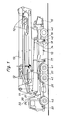
- Fig. 1 eine Seitenansicht einer Sattelzug-Betonpumpe im Zustand der Straßenfahrt mit eingeschwenkten Stützbeinen und zusammengeklapptem Verteilermast;
- Fig. 2 eine Draufsicht auf einen Ausschnitt der Sattelzug-Betonpumpe nach Fig. 1 mit ausgeschwenkten Stützbeinen;
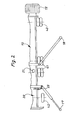
- Fig. 3 einen vergrößerten Ausschnitt aus Fig. 1 mit einem bevorzugten Hubmechanismus und den Schaltorganen einer Sicherungseinrichtung;
- Fig. 4 eine Stirnseitenansicht des Hubmechanismus nach Fig. 3 mit einem Hydraulikzylinder;
- Fig. 5 eine Stirnseitenansicht des Hubmechanismus nach Fig. mit zwei Hydraulikzylindern;
- Fig. 6 und Fig. 7 zwei weitere Ausführungsbeispiele mit abgewandelten Hubmechanismen in einer ausschnittsweisen Seitenansicht.
- Figure 1 is a side view of a tractor-trailer concrete pump in the state of driving on the road with pivoted support legs and folded boom.
- FIG. 2 shows a plan view of a section of the tractor-trailer concrete pump according to FIG. 1 with the support legs pivoted out;
- 3 shows an enlarged detail from FIG. 1 with a preferred lifting mechanism and the switching elements of a safety device;
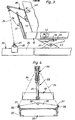
- FIG. 4 shows an end view of the lifting mechanism according to FIG. 3 with a hydraulic cylinder;
- 5 shows an end view of the lifting mechanism according to FIG. 2 with two hydraulic cylinders;
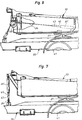
- FIGS. 6 and 7 show two further exemplary embodiments with modified lifting mechanisms in a partial side view.
Die fahrbare Betonpumpe enthält einen Sattelzug, auf dessen Sattelanhänger 10 ein an einem Drehturm 11 um eine vertikale Achse drehbarer, mit hydraulischen Mitteln 12 auseinanderklappbarer Verteilermast 13 angeordnet ist, dessen Betonleitung 14 über einen Beschikkungsbehälter 15 und ein Pumpenaggregat 16 mit dem zu fördernden Beton beaufschlagbar ist. Am Sattelanhänger 10 sind insgesamt vier seitlich ausschwenkbare und nach unten teleskopartig ausfahrbare Stützbeine 17, 18 vorgesehen (vgl. Fig. 2). Die Sattelzugmaschine 20 ist über eine an sich bekannte Sattelkupplung 21 mit dem Königszapfen 19 des Sattelanhängers 10 lösbar verbunden. Der Riegel 22 sorgt dafür, daß sowohl eine vertikale als auch eine horizontale Kraftübertragung über die Kupplung möglich ist und daß die Sattelzugmaschine dennoch um die vertikale Achse des Königszapfens 19 gegenüber dem Satellanhänger 10 verschwenkt werden kann. Der Riegel 22 kann aus Sicherheitsgründen mittels einer geeigneten Schraubverbindung so an der Sattelkupplung 21 festgelegt werden, daß er vom Bedienungspersonal nicht ohne weiteres entfernt werden kann. Das zusätzlich an der Sattelkupplung vorgesehene Drehlager 23 erlaubt eine Nickbewegung der Zugmaschine 20 um eine horizontale Querachse gegenüber dem Sattelanhänger 10.The mobile concrete pump contains a semitrailer, on the
Am vorderseitigen Ende des Sattelanhängers 10 sind zwischen dem Sattelanhänger und der Sattelzugmaschine wirkende Anhebe- und Festhaltemittel 29 angeordnet, die nachfolgend auch als Hubmechanismus bezeichnet werden.At the front end of the
Bei den in Fig. 1 bis 5 gezeigten Ausführungsbeispielen enthält der Hubmechanismus 29 mindestens einen Hebel 30, der am Drehturm 11 des Verteilermastes 13 oder am Rahmen des Sattelanhängers 10 angelenkt ist. Der Hebel 30 ist mit Hilfe eines Hydrozylinders 31 um eine quer zur Fahrtrichtung verlaufende Horizontalachse auf- und abschwenkbar (Fig.4). Statt einem können auch zwei Hydrozylinder 31 vorgesehen sein, deren Hub durch eine Querstange 33 aufeinander abstimmbar ist (Fig. 5).In the exemplary embodiments shown in FIGS. 1 to 5, the
Am freien Ende des Hebels 30 sind zwei als Gliederketten 34 ausgebildete Zugstränge eingehängt, die an ihrem unteren Ende eine an einem seitlich über den Fahrgestellrahmen 35 der Sattelzugmaschine 20 überstehenden Kopfbolzen 36 einhängbare Ringöse 37 aufweisen. Die Kopfbolzen 36 sind zweckmäßig an einer am Fahrgestellrahmen 35 befestigten Traverse 38 angeordnet, die in ihrem mittleren, in der Längsmittelebene der Sattelzugmaschine befindlichen Bereich einen weiteren Kopfbolzen 39 aufweist. Die Gliederketten 34 dienen als Zugorgan, über das beim Hochschwenken des Hebels 30 mit Hilfe des Hydrozylinders 31 die Sattelzugmaschine vom Boden abgehoben werden kann.At the free end of the
Bei den Ausführungsbeispielen nach Fig.6 6 und 7 enthält der Hubmechanismus 29 einen am Sattelanhänger 10 oder an dessen Aufbau befestigten Hydrozylinder 31', dessen Kolbenstange 45 am freien Ende ein Auge 47 oder einen Haken aufweist, an dem das als Kette oder Seil ausgebildete Zugorgan 34 befestigbar ist. Anstelle von einem können auch zwei Hydrozylinder 31' verwendet werden. Im Falle des in Fig. 6 gezeigten Ausführungsbeispiels ist das biegeschlaffe Zugorgan 34 über eine am Sattelanhänger befindliche Umlenkrolle 46 geführt.In the exemplary embodiments according to FIGS. 6 and 7, the
Im praktischen Betrieb wird nach dem Ankommen des Sattelzugs auf der Baustelle durch Ausschwenken und Ausfahren der Stützbeine 17, 18 zunächst der Sattelanhänger 10 mit seinem aus Pumpaggregat 16 und Verteilermast 13 bestehenden Aufbau angehoben, so daß die Hinterräder 40 weitgehend oder ganz vom Boden abgehoben werden. Gleichzeitig wird die Doppelachse 41 der Sattelzugmaschine 20 über die geschlossene Sattelkupplung 21 hochgezogen. Die Stützbeine 17, 18 befinden sich dabei etwa in der in Fig. 2 angedeuteten Position.In practical operation, after the semitrailer arrives at the construction site, the
Anschließend wird der Hubmechanismus 29 betätigt. Vor allem wenn die Sattelzugmaschine 20 nach dem Ankommen auf der Baustelle nicht exakt fluchtend zum Sattelanhänger 10 ausgerichtet ist, werden die Gliederketten 34 zunächst an mittleren Kopfbolzen 39 eingehängt. Beim Betätigen des bzw. der Hydrozylinder 31 bzw. 31' wird sodann der vordere Teil der Sattelzugmaschine 20 leicht angehoben und nach dem Abheben der Vorderräder 42 in eine zum Sattelanhänger 10 fluchtende Lage ausgerichtet. Nach einem nochmaligen Ablassen der Sattelzugmaschine können dann die Gliederketten 34 an den seitlich überstehenden Kopfbolzen 36 eingehängt werden. Beim anschließenden Betätigen des Hydrozylinders 31 bzw. 31' wird die Sattelzugmaschine 20 mit ihren Vorderrädern 42 vom Boden abgehoben und wirkt dann bei ebenfalls vom Boden freikommenden Hinterrädem 41 als Ballastgewicht zur Stabilisierung des Sattelanhängers bei ausgeklapptem Verteilermast.The
Damit die Sattelzugmaschine 20 beim Schwenken des schweren Verteilermastes 13 keine unerwünschten Schwingungen ausführt, kann sie in der ausgerichteten Stellung verriegelt werden. Dies kann mit einem nicht dargestellten, an sich bekannten Keil erfolgen, der in den Einfahrschlitz der Sattelkupplung 21 hydraulisch eingeschoben wird. Weiter können zu diesem Zweck zwischen dem Sattelanhänger 10 und dem Fahrgestell 35 der Sattelzugmaschine 20 zusätzliche, in der Zeichnung nicht dargestellte Hydraulikzylinder angebracht werden. Auch mit Hilfe fester, i' der Zeichnung nicht dargestellter Zugstangen, Dreieckslenkern od. dgl. anstelle der Gliederketten kann eine Fixierung der angehobenen Saitelzugmaschine gegenüber dem Sattelanhänger bewirkt werden.So that the
Um ein versehentliches Ausfahren des Verteilermastes bei nicht ausreichendem Böllastgewicht zu verhindern, ist eine Sicherungseinrichtung vorgesehen, die die Druckölzufuhr zur Verteitermasthydrautiksperrt, wenn der Sattelanhänger abgesattelt ist und/oder wenn die Sattelzugmaschine nicht vom Boden abgehoben ist. Zu diesem Zweck sind am Sattelanhänger zwei als Öffner ausgeb Idete Schaltventile 44,45 angeordnet, die im einen Falle durch die Kupplungsplatte der Sattelkupplung 21 und im anderen Falle durch den Hebel 30 in dessen nach oben geschwenkter Endlage betätigt werden (Fig. 3). Selbstverständlich kann die Sicherungseinrichtung auch in anderer Weise realisiert werden, wie z. B. durch ein auf die Last der angehobenen Sattelzugmaschine ansprechendes, mit dem Hydrozylinder 31 verbundenes Druckschaltventil.To prevent inadvertent extension of the placing boom when the weight of the boom load is insufficient, a safety device is provided that blocks the pressure oil supply to the distributor boom hydraulics when the semitrailer is unsaddled and / or when the tractor unit is not lifted off the ground. For this purpose, two switching
Die Gliederketten 34 erlauben es, die Sattelzugmaschine nach Arbeitsschluß wieder in die ursprüngliche, gegenüber dem Sattelanhänger abgewickelte Stellung zu schwenken, indem nach kurzzeitigem Absenken des Vorderteils der Zugmaschine 20 die Ketten 34 an einer anderen Stelle des Fahrgestellrahmens 35 bzw. der Traverse 38 so eingehängt werden, daß die Zugmaschine beim Wiederanheben gegenüber dem Sattelanhänger zur vorgesehenen Seite hin geschwenkt werden kann. Der Sattelzug kann dann vor allem bei engen Baustellen in seiner ursprünglichen Fahrtrichtung wieder zurückfahren und die Baustelle verlassen.The
Zur Einsparung eines Separatmotors auf dem Sattelanhänger ist es möglich, den Fahrzeugmotor der Sattelzugmaschine 20 zum Antrieb des Pumpaggregats 16 heranzuziehen. Dies kann mit Hilfe von zwischen der Sattelzugmaschine und dem Sattelanhänger verlegbaren gelenkigen Hydraulikleitungen erfolgen. Eine andere Möglichkeit besteht darin, daß in der Arbeitsstellung mit angehobener Sattelzugmaschine eine mechanische Kupplung zwischen Sattelzugmaschine und Sattelzuganhänger eingerückt wird, die über eine Kardanwelle eine auf dem Sattelanhänger angeordnete Hydropumpe mit dem Fahrzeugmotor der Zugmaschine kraftschlüssig verbindet. Im Hinblick auf die erforderliche Pumpleistung setzt dies allerdings einen leistungsfähigen Fahrzeugmotor in der Sattelzugmaschine voraus. Außerdem besteht dann die Einschränkung, daß der Sattelanhänger nicht mehr mit jeder beliebigen Sattelzugmaschine verbunden werden kann.To save a separate motor on the semitrailer, it is possible to use the vehicle motor of the
Mit dem oben beschriebenen Hubmechanismus ist es grundsätzlich auch möglich, im abgesattelten Zustand statt der Sattelzugmaschine ein anderes Ballastgewicht anzuheben. Dies ist etwa dann von Vorteil, wenn die Sattelzugmaschine auch noch anderweitig eingesetzt oder repariert werden muß und dabei Ausfallzeiten der Betonpumpe an der Baustelle vermieden werden sollen.With the lifting mechanism described above, it is also possible in principle to lift another ballast weight in the unsaddled state instead of the tractor unit. This is of advantage, for example, if the tractor unit also has to be used or repaired in another way and downtimes of the concrete pump at the construction site are to be avoided.
Anstelle eines Hydrozylinders 31 bzw. 31' kann auch eine in der Zeichnung nicht dargestellte Seilwinde als Hubmechanismus verwendet werden. Wenn die Seilwinde im hinteren Bereich des Sattelanhängers 10 in der Nähe des Beschickungsbehälters 15 angeordnet ist, kann sie erforderlichenfalls auch als Schleppwinde für das Fahrzeug verwendet werden.Instead of a
Grundsätzlich ist sogar eine Anordnung denkbar, bei der der Sattelanhänger 10 und die Sattelzugmaschine 20 lediglich mit einem strammgezogenen Zugorgan verbunden werden, so daß das Anheben der Sattelzugmaschine ohne zusätzlichen Hubmechanismus anschließend beim Ausfahren der vorderen Stützbeine erfolgen kann.In principle, an arrangement is also conceivable in which the
Claims (16)
Priority Applications (1)
| Application Number | Priority Date | Filing Date | Title |
|---|---|---|---|
| AT81102490T ATE5667T1 (en) | 1980-04-26 | 1981-04-02 | SELF-PROPELLED CONCRETE PUMP. |
Applications Claiming Priority (2)
| Application Number | Priority Date | Filing Date | Title |
|---|---|---|---|
| DE3016232 | 1980-04-26 | ||
| DE19803016232 DE3016232A1 (en) | 1980-04-26 | 1980-04-26 | SELF-DRIVING CONCRETE PUMP |
Publications (3)
| Publication Number | Publication Date |
|---|---|
| EP0038954A2 EP0038954A2 (en) | 1981-11-04 |
| EP0038954A3 EP0038954A3 (en) | 1981-12-23 |
| EP0038954B1 true EP0038954B1 (en) | 1983-12-21 |
Family
ID=6101090
Family Applications (1)
| Application Number | Title | Priority Date | Filing Date |
|---|---|---|---|
| EP81102490A Expired EP0038954B1 (en) | 1980-04-26 | 1981-04-02 | Self-propelled concrete pump |
Country Status (5)
| Country | Link |
|---|---|
| US (1) | US4418713A (en) |
| EP (1) | EP0038954B1 (en) |
| AT (1) | ATE5667T1 (en) |
| BR (1) | BR8102515A (en) |
| DE (2) | DE3016232A1 (en) |
Cited By (5)
| Publication number | Priority date | Publication date | Assignee | Title |
|---|---|---|---|---|
| WO2004113648A1 (en) | 2003-06-25 | 2004-12-29 | Putzmeister Aktiengesellschaft | Mobile concrete pump with distributing boom |
| WO2004113646A1 (en) | 2003-06-25 | 2004-12-29 | Putzmeister Aktiengesellschaft | Movable concrete pump comprising a distribution boom |
| WO2009097933A1 (en) | 2008-02-06 | 2009-08-13 | Putzmeister Concrete Pumps Gmbh | Wheeled working machine |
| CN102287055A (en) * | 2011-06-28 | 2011-12-21 | 三一重工股份有限公司 | Concrete pump truck |
| CN102943567A (en) * | 2012-11-30 | 2013-02-27 | 上海汽车改装厂有限公司 | Cantilever support and concrete pump truck provided with same |
Families Citing this family (14)
| Publication number | Priority date | Publication date | Assignee | Title |
|---|---|---|---|---|
| US4640533A (en) * | 1985-10-04 | 1987-02-03 | Construction Forms, Inc. | Adjustable pipe extender for high pressure lines carrying abrasive materials |
| US4848012A (en) * | 1987-07-27 | 1989-07-18 | Zimmerman Harold M | Multi-purpose earthworking machine |
| DE3830315A1 (en) * | 1988-09-07 | 1990-03-08 | Putzmeister Maschf | MOBILE CONCRETE PUMP |
| US5029895A (en) * | 1989-07-11 | 1991-07-09 | Schwing America, Inc. | Outrigger-mounted axle assembly |
| AU3427893A (en) * | 1991-12-31 | 1993-07-28 | Gilbert A. Loya | Multipurpose concrete placer with universal attachment for a rough terrain vehicle or crane |
| DE10032622A1 (en) * | 2000-07-07 | 2002-01-17 | Putzmeister Ag | Concrete pumping vehicle as footed boom reciprocates boom by double-acting hydraulic cylinder led through boom box and telescoping parts so box swivel axis intersects cylinder axis at right angles. |
| DE10112084A1 (en) * | 2001-03-12 | 2002-09-19 | Putzmeister Ag | Mobile thick matter pump with support structure and air-sprung wheel axle |
| US6588448B1 (en) * | 2002-01-07 | 2003-07-08 | Glazer Enterprises, Inc. | Telescopic boom-mounted concrete pump apparatus |
| DE10328769A1 (en) | 2003-06-25 | 2005-01-20 | Putzmeister Ag | Articulated mast for mobile concrete pumps |
| US7398981B1 (en) | 2003-11-20 | 2008-07-15 | Schwing America, Inc. | Auxiliary axle system for concrete pump truck |
| DE102008007917A1 (en) * | 2008-02-06 | 2009-08-13 | Putzmeister Concrete Pumps Gmbh | Mobile working machine |
| CN102364007B (en) * | 2011-10-31 | 2014-02-19 | 中联重科股份有限公司 | Concrete pump vehicle and inter-arm supporting device of folded arm frame |
| ES2425434B1 (en) * | 2012-04-12 | 2014-09-16 | Gicalla, S.A. | Quick concrete remover-unloader tilting equipment |
| DE102014200396A1 (en) * | 2014-01-13 | 2015-07-30 | Putzmeister Engineering Gmbh | Truck-mounted concrete pump and protection circuit for it |
Citations (1)
| Publication number | Priority date | Publication date | Assignee | Title |
|---|---|---|---|---|
| DE2737884A1 (en) * | 1977-08-23 | 1979-03-08 | Schlecht Karl | Saddle-back chassis-mounted concrete distributing pump - has pump filler funnel at vehicle front with lowerable pair of shafts |
Family Cites Families (7)
| Publication number | Priority date | Publication date | Assignee | Title |
|---|---|---|---|---|
| DE7240480U (en) * | 1975-07-24 | Zimmermann W | Mobile hoist | |
| US2883208A (en) * | 1955-04-28 | 1959-04-21 | Sentinel Shrewsbury Ltd | Tractor-trailer load distributing coupling |
| US2899004A (en) * | 1955-07-08 | 1959-08-11 | Simmons Lovel Reynolds | Weight-transferring hitch for four-wheel-drive tractors |
| GB1083794A (en) * | 1964-11-09 | 1967-09-20 | Century Fabrications 100 Ltd | Cranes and other load shifting apparatus |
| US3985036A (en) * | 1973-02-15 | 1976-10-12 | Challenge-Cook Bros., Incorporated | Outrigger and mounting means for truck with a conveyor boom |
| US4130134A (en) * | 1976-12-13 | 1978-12-19 | Morgen Manufacturing Company | Material conveying apparatus |
| DE2729750A1 (en) * | 1977-07-01 | 1979-01-18 | Scheele Maschf W | Lorry carried three-piece concrete supply flexible jib - has bottom arm on full circle driven rotary hinge with lengthways axis |
-
1980
- 1980-04-26 DE DE19803016232 patent/DE3016232A1/en not_active Withdrawn
-
1981
- 1981-04-02 EP EP81102490A patent/EP0038954B1/en not_active Expired
- 1981-04-02 AT AT81102490T patent/ATE5667T1/en not_active IP Right Cessation
- 1981-04-02 DE DE8181102490T patent/DE3161686D1/en not_active Expired
- 1981-04-24 BR BR8102515A patent/BR8102515A/en unknown
- 1981-04-27 US US06/257,856 patent/US4418713A/en not_active Expired - Lifetime
Patent Citations (1)
| Publication number | Priority date | Publication date | Assignee | Title |
|---|---|---|---|---|
| DE2737884A1 (en) * | 1977-08-23 | 1979-03-08 | Schlecht Karl | Saddle-back chassis-mounted concrete distributing pump - has pump filler funnel at vehicle front with lowerable pair of shafts |
Cited By (6)
| Publication number | Priority date | Publication date | Assignee | Title |
|---|---|---|---|---|
| WO2004113648A1 (en) | 2003-06-25 | 2004-12-29 | Putzmeister Aktiengesellschaft | Mobile concrete pump with distributing boom |
| WO2004113646A1 (en) | 2003-06-25 | 2004-12-29 | Putzmeister Aktiengesellschaft | Movable concrete pump comprising a distribution boom |
| WO2009097933A1 (en) | 2008-02-06 | 2009-08-13 | Putzmeister Concrete Pumps Gmbh | Wheeled working machine |
| CN102287055A (en) * | 2011-06-28 | 2011-12-21 | 三一重工股份有限公司 | Concrete pump truck |
| CN102943567A (en) * | 2012-11-30 | 2013-02-27 | 上海汽车改装厂有限公司 | Cantilever support and concrete pump truck provided with same |
| CN102943567B (en) * | 2012-11-30 | 2016-04-06 | 上海汽车改装厂有限公司 | A kind of cantilever support and there is the concrete mixer of this support |
Also Published As
| Publication number | Publication date |
|---|---|
| DE3161686D1 (en) | 1984-01-26 |
| ATE5667T1 (en) | 1984-01-15 |
| EP0038954A2 (en) | 1981-11-04 |
| BR8102515A (en) | 1982-01-05 |
| EP0038954A3 (en) | 1981-12-23 |
| DE3016232A1 (en) | 1981-11-05 |
| US4418713A (en) | 1983-12-06 |
Similar Documents
| Publication | Publication Date | Title |
|---|---|---|
| EP0038954B1 (en) | Self-propelled concrete pump | |
| EP0593390B1 (en) | Mobile crane | |
| DE1944214B2 (en) | RAILLESS MOVABLE ROTARY CRANE UNDERCARRIAGE | |
| AT523097B1 (en) | TRUCKLE CRANE WITH A TELESCOPIC BOOM AND TRUCKLE CRANE SYSTEM AND METHODS OF ATTACHING A GUYING DEVICE TO THE TELESCOPIC BOOM OF A TRUCKLE CRANE | |
| DE3139596A1 (en) | HEAVY DUTY TELESCOPIC CRANE | |
| DE2015792C2 (en) | Agricultural vehicle to be used as an agricultural tractor | |
| DE19823380A1 (en) | Device for reducing the axle load of a multi-axle mobile telescopic crane | |
| DE2944289A1 (en) | LIFTING VEHICLE | |
| DE3911868C2 (en) | ||
| EP1037848B1 (en) | Travelling mechanism for an extensively overhanging working device such as a building crane | |
| EP0919508B1 (en) | Crane having a holding device | |
| DE19728822B4 (en) | Cultivation trailing suspension | |
| DE102020121344A1 (en) | Mobile crane with trailer | |
| DE10127964A1 (en) | Floor conveyor vehicle has portal-like chassis with wheels at bottom of perpendicular stands and with connecting assemblies attached at free ends by articulated joints to each other frame for constant contact of wheels on ground | |
| DE3245095C2 (en) | ||
| DE19948143C2 (en) | Rail bogie with integrated tilt compensation for two-way vehicles | |
| DE102021111922B3 (en) | Guying system and method for a mobile crane telescopic boom | |
| DE3109831C2 (en) | Self-propelled mobile crane | |
| DE2737884A1 (en) | Saddle-back chassis-mounted concrete distributing pump - has pump filler funnel at vehicle front with lowerable pair of shafts | |
| DE2848387A1 (en) | Prefabricated garage moving and erecting vehicle - includes lifting crane jib and swivelling and locking rear ground support mechanism | |
| EP3393963B1 (en) | Modular crane, transport unit for a modular crane and method for operating a crane of this type | |
| AT201648B (en) | Mobile multi-purpose construction device | |
| DE4024608C2 (en) | Truck with a hydraulic support device | |
| EP4053066A2 (en) | Device and method for fitting / removing a mobile crane boom | |
| DE19938545A1 (en) | Loading crane for load vehicle |
Legal Events
| Date | Code | Title | Description |
|---|---|---|---|
| PUAI | Public reference made under article 153(3) epc to a published international application that has entered the european phase |
Free format text: ORIGINAL CODE: 0009012 |
|
| PUAL | Search report despatched |
Free format text: ORIGINAL CODE: 0009013 |
|
| AK | Designated contracting states |
Designated state(s): AT DE IT NL |
|
| AK | Designated contracting states |
Designated state(s): AT DE IT NL |
|
| RBV | Designated contracting states (corrected) |
Designated state(s): AT DE IT NL |
|
| 17P | Request for examination filed |
Effective date: 19820317 |
|
| ITF | It: translation for a ep patent filed |
Owner name: STUDIO JAUMANN |
|
| GRAA | (expected) grant |
Free format text: ORIGINAL CODE: 0009210 |
|
| STAA | Information on the status of an ep patent application or granted ep patent |
Free format text: STATUS: THE PATENT HAS BEEN GRANTED |
|
| AK | Designated contracting states |
Designated state(s): AT DE IT NL |
|
| PG25 | Lapsed in a contracting state [announced via postgrant information from national office to epo] |
Ref country code: NL Effective date: 19831221 |
|
| REF | Corresponds to: |
Ref document number: 5667 Country of ref document: AT Date of ref document: 19840115 Kind code of ref document: T |
|
| REF | Corresponds to: |
Ref document number: 3161686 Country of ref document: DE Date of ref document: 19840126 |
|
| PG25 | Lapsed in a contracting state [announced via postgrant information from national office to epo] |
Ref country code: AT Effective date: 19840402 |
|
| NLV1 | Nl: lapsed or annulled due to failure to fulfill the requirements of art. 29p and 29m of the patents act | ||
| PLBI | Opposition filed |
Free format text: ORIGINAL CODE: 0009260 |
|
| 26 | Opposition filed |
Opponent name: FRIEDRICH WILH. SCHWING GMBH Effective date: 19840919 |
|
| PLBG | Opposition deemed not to have been filed |
Free format text: ORIGINAL CODE: 0009274 |
|
| 26D | Opposition deemed not to have been filed |
Opponent name: FRIEDRICH WILH. SCHWING GMBH Effective date: 19840922 |
|
| ITTA | It: last paid annual fee | ||
| PGFP | Annual fee paid to national office [announced via postgrant information from national office to epo] |
Ref country code: DE Payment date: 19990424 Year of fee payment: 19 |
|
| PG25 | Lapsed in a contracting state [announced via postgrant information from national office to epo] |
Ref country code: DE Free format text: LAPSE BECAUSE OF NON-PAYMENT OF DUE FEES Effective date: 20000430 |