EP0038727A1 - Relais électromagnétique à armature pivotante à aimant permanent - Google Patents
Relais électromagnétique à armature pivotante à aimant permanent Download PDFInfo
- Publication number
- EP0038727A1 EP0038727A1 EP81400416A EP81400416A EP0038727A1 EP 0038727 A1 EP0038727 A1 EP 0038727A1 EP 81400416 A EP81400416 A EP 81400416A EP 81400416 A EP81400416 A EP 81400416A EP 0038727 A1 EP0038727 A1 EP 0038727A1
- Authority
- EP
- European Patent Office
- Prior art keywords
- cylinder head
- contacts
- armature
- fixed
- fixed contacts
- Prior art date
- Legal status (The legal status is an assumption and is not a legal conclusion. Google has not performed a legal analysis and makes no representation as to the accuracy of the status listed.)
- Ceased
Links
- 239000011810 insulating material Substances 0.000 claims description 6
- 239000011248 coating agent Substances 0.000 claims description 4
- 238000000576 coating method Methods 0.000 claims description 4
- 230000000149 penetrating effect Effects 0.000 claims 1
- 230000000694 effects Effects 0.000 description 3
- 230000003071 parasitic effect Effects 0.000 description 3
- 238000005452 bending Methods 0.000 description 2
- 238000004140 cleaning Methods 0.000 description 2
- 239000000463 material Substances 0.000 description 2
- 239000004020 conductor Substances 0.000 description 1
- 238000010276 construction Methods 0.000 description 1
- 230000005284 excitation Effects 0.000 description 1
- 238000009413 insulation Methods 0.000 description 1
- 238000002955 isolation Methods 0.000 description 1
Images

Classifications
-
- H—ELECTRICITY
- H01—ELECTRIC ELEMENTS
- H01H—ELECTRIC SWITCHES; RELAYS; SELECTORS; EMERGENCY PROTECTIVE DEVICES
- H01H51/00—Electromagnetic relays
- H01H51/22—Polarised relays
- H01H51/2227—Polarised relays in which the movable part comprises at least one permanent magnet, sandwiched between pole-plates, each forming an active air-gap with parts of the stationary magnetic circuit
-
- H—ELECTRICITY
- H01—ELECTRIC ELEMENTS
- H01H—ELECTRIC SWITCHES; RELAYS; SELECTORS; EMERGENCY PROTECTIVE DEVICES
- H01H50/00—Details of electromagnetic relays
- H01H50/16—Magnetic circuit arrangements
- H01H50/18—Movable parts of magnetic circuits, e.g. armature
- H01H50/24—Parts rotatable or rockable outside coil
Definitions
- the present invention relates to a bistable electromagnetic relay with pivoting armature provided with a permanent magnet.
- Relays of this type essentially consist of a U-shaped cylinder head fixed on a base and provided with one or two excitation coils.
- This cylinder head cooperates with an H-shaped frame formed of a permanent magnet constituting the bar of the H and on which are fixed two protruding plates forming pole pieces and constituting the branches of the H.
- the ends of the cylinder head are housed with a large clearance between these branches, so that, according to the respective polarities applied to these ends, the overflowing plates are glued to it in an oblique position of the frame, in a direction or in the other.
- the pivoting frame is covered externally with an insulating material and carries flexible blades carrying movable contacts and extending along the branches of the H to cooperate with fixed contacts carried by the base.
- the present invention aims to provide a relay with pivoting armature which is free from the aforementioned drawbacks.
- the electromagnetic relay with pivoting armature conforms to the description which was given above and it is characterized in that each flexible blade carries on its free end two movable contacts electrically connected cooperating with contacts fixed to connect them to each other.
- the closure is effected by a very short bridging of the fixed contacts by means of the electrical connection between the movable contacts, a connection which only interests a very small part of the flexible blade.
- This blade therefore does not have to be permanently connected to a fixed terminal by any connection, and the current path in the relay is very short.
- this double break reduces the parasitic capacitance between open contacts.
- the axis of rotation of the armature is located between the fixed contacts and the point of attachment of the flexible blade to the armature:
- This arrangement increases, on closing, the lateral friction of the movable contacts on the fixed contacts and the self-cleaning effect.
- the two movable contacts of the same blade remain located in the same plane parallel to the axis of the cylinder head, and the corresponding fixed contacts are located in the same plane parallel to the plane of the cylinder head , the face of the base which carries these fixed contacts being perpendicular to the plane of the cylinder head and parallel to the axis of said cylinder head.
- the relay comprises two flexible flexible blades on either side of the armature to cooperate with two pairs of respective fixed contacts, so as to constitute a double-contact change-over contact circuit cut without common point.
- the relay comprises three equidistant fixed contacts spaced at a predetermined pitch, and a flexible blade cambered so that a movable contact is located in each interval between the fixed contacts, the movable contacts being offset relative to each other by the value due not mentioned above.
- each branch of the cylinder head is provided with a coil, and the ends of these branches have flats for cooperating plane on plane with the protruding plates of the pivoting frame in its extreme angular positions.
- the assembly formed by the cylinder head and its coils is overmolded in an insulating material to form a parallelepipedic block, a first face of which carries terminals for connection of the coils and fixed contacts, and a second face of which is perpendicular to the first. , leaves the ends of the branches of the cylinder head emerging and comprises means for centering and pivoting the armature coaxially with the cylinder head.
- a perfectly protected block is thus produced from which only the ends of the cylinder head and the lugs to be connected emerge.
- the coil is therefore not likely to pollute the contacts.
- the aforementioned second face of the block is surrounded by a skirt extending the block and enclosing the ends of the legs of the cylinder head, and this skirt is designed to receive a cover comprising part of the centering and pivoting of the armature.
- the operation of the relay can thus be inspected before fitting the cover.
- the latter is simpler to produce than a cover.
- the relay comprises a removable trough provided to adapt to the aforementioned second face of the block, and this trough comprises, on its bottom, part of the means for centering and pivoting the armature and, on one of its sides, fixed contacts.
- This embodiment makes it possible to use two different insulating materials for overmolding and for the trough, the second being able in particular to be adapted, for example, to high-frequency isolation.
- the cylinder head comprises two additional branches opposite the first, arranged symmetrically and overmolded with it in the same block to cooperate with a second armature symmetrical to the first and provided with similar contact circuits.
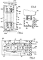
- a relay according to the invention comprises a U-shaped cylinder head 1 fixed on a plate 2 of a base 3, on the two branches 4 of which are wound coils 5.
- the two branches 4 protrude of the plate 2 in order to be housed with a large clearance between the branches of a pivoting frame 6 in H, the pivot axis being coincident with the axis of the cylinder head 1.
- This frame consists essentially of a permanent magnet 7 forming the bar of the H on which are fixed two protruding plates 8a, 8b forming pole pieces. These plates are covered externally with an insulating coating 9 completed by two insulating plates 11a, 11b covering the magnet 7 and provided with housings for receiving pivots 12a, 12b secured to a base 3 which serve to center and to allow the l 'frame 6.
- the ends of the branches 5 of the cylinder head are provided with flats 13 arranged to allow plane cooperation on plan of the protruding plates 8a, 8b with said branches.
- each blade On the insulating coating 9 are fixed two flexible strips 14 of conductive material by one of their ends along each projecting plate 8a, 8b. At the other end of each blade are fixed two movable contacts 15a, 15b to cooperate with fixed contacts 16a, 16b.
- the attachment point 17 of each blade is located such that the axis of the pivots 12a, 12b is located between the movable contacts and said attachment point.
- the fixed contacts 16a and 16b corresponding to the same blade are located in the same plane parallel to the plane of the cylinder head 1 and are connected directly and without bending to respective lugs 18a, 18b emerging from one face 19 of the base which carries these contacts and which is perpendicular to the plane of the cylinder head and parallel to the axis of the cylinder head.
- This face 19 also carries terminals 21 for output of the coils 5 (connection not shown).
- the armature 6 pivots so, for example, that, with reference to FIG. 1, the plate 8a comes to apply on the branch 4 of left, and that the plate 8b comes to apply on the branch of right.
- the movement of the lower blade 14 then applies the movable contacts 15a, 15b to the fixed contacts 16a, 16b ( Figure 2). These fixed contacts are then electrically connected by a very short portion of the blade 14, of negligible resistance.
- each movable blade provides a significant accompanying effect which causes, on closing, a lateral friction of the movable contacts on the fixed contacts, which has the effect of self-cleaning of the contacts.
- the blades 14 do not play any conducting role and do not have to be connected to an output terminal by a connection which should be flexible.
- the relay which has just been described constitutes a double-break change-over contact circuit with no common point.
- a U-shaped cylinder head provided with two coils 105 has two branches 104 located between the branches 108a, 108b of an armature 106 in H pivotally mounted and comprising a permanent magnet 107.
- this frame On one side of its coating insulating 109, this frame carries a flexible blade 114 which comprises two branches 114a, 114b each carrying a movable contact, respectively 115a, 115b, each of these contacts operating on the two faces of the blade.
- Three fixed contacts 116a, 116b, 116c are arranged on the face 119 of the base 103 so that they are regularly spaced by a predetermined pitch. These contacts are extended by lugs 118a, 118b, 118c.
- the distance between the branches 114a and 114b of the blade 114 is equal to the aforementioned pitch, so that, in an extreme position of the frame 6, the movable contact 115a comes on the contact 116a and the movable contact 115b on the contact 116b , whereas, in the other extreme position, the movable contact 115a comes on the contact 116b, the movable contact 115b coming on the contact 116c.
- FIG. 4 shows a variant in which the yoke 201 comprises two additional branches 204a opposite the branches 204 and arranged symmetrically to cooperate with a second frame (not shown) corresponding to two other pairs of fixed contacts 223a, 223b.
- the block 222 is extended on each side of the relay by a skirt, respectively 224a, 224b in which the fixed contacts are fixed.
- the pivots 212a of the frame are integral with the block 222, while the pivots 212b are integral with removable covers 225a, 225b which close the skirts 224a, 224b respectively. Before fitting the covers, the skirts protect the moving parts of the relay.
- the skirts are eliminated and a trough 327 comes to cooperate with the block 322 taking the place of both the skirt and the cover.
- a pivot 312b for the frame (not shown) and on one of the faces are fixed fixed contacts 316a, 316b which are extended by lugs 318a, 318b.
- This arrangement makes it possible to provide a different insulating material for the block 222 and for the trough 327 which carries the contacts.
- a material may be chosen for the block which is suitable for overmolding and, for the trough, a material providing good insulation at high frequencies.
Landscapes
- Physics & Mathematics (AREA)
- Electromagnetism (AREA)
- Electromagnets (AREA)
- Breakers (AREA)
Applications Claiming Priority (2)
| Application Number | Priority Date | Filing Date | Title |
|---|---|---|---|
| FR8006302A FR2486303A1 (fr) | 1980-03-21 | 1980-03-21 | Relais electromagnetique a armature pivotante a aimant permanent |
| FR8006302 | 1980-03-21 |
Publications (1)
| Publication Number | Publication Date |
|---|---|
| EP0038727A1 true EP0038727A1 (fr) | 1981-10-28 |
Family
ID=9239924
Family Applications (1)
| Application Number | Title | Priority Date | Filing Date |
|---|---|---|---|
| EP81400416A Ceased EP0038727A1 (fr) | 1980-03-21 | 1981-03-18 | Relais électromagnétique à armature pivotante à aimant permanent |
Country Status (4)
| Country | Link |
|---|---|
| US (1) | US4367447A (ref) |
| EP (1) | EP0038727A1 (ref) |
| JP (1) | JPS56160736A (ref) |
| FR (1) | FR2486303A1 (ref) |
Cited By (9)
| Publication number | Priority date | Publication date | Assignee | Title |
|---|---|---|---|---|
| DE3224468A1 (de) * | 1982-06-30 | 1984-01-05 | Siemens AG, 1000 Berlin und 8000 München | Relais mit brueckenkontaktfeder |
| DE3223867A1 (de) * | 1982-06-25 | 1984-01-05 | Siemens AG, 1000 Berlin und 8000 München | Polarisiertes relais |
| EP0113440A1 (de) * | 1982-12-07 | 1984-07-18 | Siemens Aktiengesellschaft | Elektromagnetisches Relais |
| EP0110579A3 (en) * | 1982-11-02 | 1986-10-01 | Nec Corporation | Polar relay |
| EP0096350A3 (en) * | 1982-06-03 | 1986-12-30 | Siemens Aktiengesellschaft Berlin Und Munchen | Electromagnetic relay with rotating armature |
| EP0130511B1 (de) * | 1983-06-28 | 1989-06-14 | Hengstler GmbH Geschäftsbereich Haller-Relais | Elektromagnetisches Relais mit Umschaltfeder |
| DE3837666A1 (de) * | 1988-11-05 | 1990-05-10 | Gruner Kg Relais Fabrik | Relais |
| EP0192928B1 (de) * | 1985-02-12 | 1990-06-13 | Siemens Aktiengesellschaft | Elektromagnetisches Relais |
| EP1840923A3 (en) * | 2006-03-30 | 2007-12-26 | TYCO Electronics Austria GmbH | Magnet system with H-shaped armature for a relay |
Families Citing this family (4)
| Publication number | Priority date | Publication date | Assignee | Title |
|---|---|---|---|---|
| DE19933797A1 (de) * | 1999-07-19 | 2001-03-08 | Tyco Electronics Logistics Ag | Relais mit Wippanker |
| WO2012128072A1 (ja) * | 2011-03-22 | 2012-09-27 | パナソニック株式会社 | 接点装置 |
| GB201215926D0 (en) * | 2012-09-06 | 2012-10-24 | Dialight Europ Ltd | Improvements in rotary actuators |
| DE102014103247A1 (de) * | 2014-03-11 | 2015-09-17 | Tyco Electronics Austria Gmbh | Elektromagnetisches Relais |
Citations (4)
| Publication number | Priority date | Publication date | Assignee | Title |
|---|---|---|---|---|
| US2741728A (en) * | 1952-08-29 | 1956-04-10 | Ericsson Telephones Ltd | Polarized electromagnetic devices |
| DE2262669A1 (de) * | 1972-12-21 | 1974-06-27 | Telefonbau & Normalzeit Gmbh | Elektromagnetisches hochzuverlaessiges relais |
| FR2271654A1 (ref) * | 1974-05-15 | 1975-12-12 | Matsushita Electric Works Ltd | |
| FR2392484A1 (fr) * | 1977-05-24 | 1978-12-22 | Siemens Ag | Relais electromagnetique |
Family Cites Families (1)
| Publication number | Priority date | Publication date | Assignee | Title |
|---|---|---|---|---|
| DE2407184C2 (de) | 1974-02-15 | 1982-09-02 | Schaltbau GmbH, 8000 München | Elektromagnetisches Relais mit zwei Ankern |
-
1980
- 1980-03-21 FR FR8006302A patent/FR2486303A1/fr active Granted
-
1981
- 1981-03-10 US US06/242,390 patent/US4367447A/en not_active Expired - Fee Related
- 1981-03-18 EP EP81400416A patent/EP0038727A1/fr not_active Ceased
- 1981-03-20 JP JP3967981A patent/JPS56160736A/ja active Pending
Patent Citations (4)
| Publication number | Priority date | Publication date | Assignee | Title |
|---|---|---|---|---|
| US2741728A (en) * | 1952-08-29 | 1956-04-10 | Ericsson Telephones Ltd | Polarized electromagnetic devices |
| DE2262669A1 (de) * | 1972-12-21 | 1974-06-27 | Telefonbau & Normalzeit Gmbh | Elektromagnetisches hochzuverlaessiges relais |
| FR2271654A1 (ref) * | 1974-05-15 | 1975-12-12 | Matsushita Electric Works Ltd | |
| FR2392484A1 (fr) * | 1977-05-24 | 1978-12-22 | Siemens Ag | Relais electromagnetique |
Non-Patent Citations (1)
| Title |
|---|
| Bell Laboratories Record, Vol. 44, Juin 1963 Murray Hill, US C. SCHNEIDER: "A Miniature Latch-in Relay for the Telstar Satellite pages 241-243 * page 242, page 243, colonne de gauche, ligne 21 * * |
Cited By (10)
| Publication number | Priority date | Publication date | Assignee | Title |
|---|---|---|---|---|
| EP0096350A3 (en) * | 1982-06-03 | 1986-12-30 | Siemens Aktiengesellschaft Berlin Und Munchen | Electromagnetic relay with rotating armature |
| DE3223867A1 (de) * | 1982-06-25 | 1984-01-05 | Siemens AG, 1000 Berlin und 8000 München | Polarisiertes relais |
| DE3224468A1 (de) * | 1982-06-30 | 1984-01-05 | Siemens AG, 1000 Berlin und 8000 München | Relais mit brueckenkontaktfeder |
| EP0110579A3 (en) * | 1982-11-02 | 1986-10-01 | Nec Corporation | Polar relay |
| EP0113440A1 (de) * | 1982-12-07 | 1984-07-18 | Siemens Aktiengesellschaft | Elektromagnetisches Relais |
| EP0130511B1 (de) * | 1983-06-28 | 1989-06-14 | Hengstler GmbH Geschäftsbereich Haller-Relais | Elektromagnetisches Relais mit Umschaltfeder |
| EP0192928B1 (de) * | 1985-02-12 | 1990-06-13 | Siemens Aktiengesellschaft | Elektromagnetisches Relais |
| DE3837666A1 (de) * | 1988-11-05 | 1990-05-10 | Gruner Kg Relais Fabrik | Relais |
| EP1840923A3 (en) * | 2006-03-30 | 2007-12-26 | TYCO Electronics Austria GmbH | Magnet system with H-shaped armature for a relay |
| US7495535B2 (en) | 2006-03-30 | 2009-02-24 | Tyco Electronics Austria Gmbh | Magnet system with H-shaped armature for a relay |
Also Published As
| Publication number | Publication date |
|---|---|
| US4367447A (en) | 1983-01-04 |
| FR2486303A1 (fr) | 1982-01-08 |
| JPS56160736A (en) | 1981-12-10 |
| FR2486303B1 (ref) | 1983-04-01 |
Similar Documents
| Publication | Publication Date | Title |
|---|---|---|
| CA1202654A (fr) | Relais coaxial inverseur hyperfrequence | |
| EP0433184B1 (fr) | Disjoncteur hybride moyenne tension | |
| FR2486303A1 (fr) | Relais electromagnetique a armature pivotante a aimant permanent | |
| EP4195229A1 (fr) | Appareil de coupure de courant sur une ligne électrique comprenant une ampoule à vide | |
| FR2517113A1 (fr) | Dispositif a contacts multiples pour appareils de commutation | |
| EP0599742B1 (fr) | Mécanisme d'ouverture et de fermeture pour interrupteur électrique moyenne ou haute tension | |
| EP0693763A1 (fr) | Interrupteurs électriques moyenne tension | |
| FR2696040A1 (fr) | Appareil interrupteur à contacts pour montage sur circuit imprimé. | |
| EP0335774A1 (fr) | Déclencheur magnétique pour disjoncteur | |
| FR2744284A1 (fr) | Interrupteur ou disjoncteur multipolaire moyenne tension | |
| CA1130352A (fr) | Chambre de soufflage pour appareil electrique limiteur de courant | |
| BE1004594A3 (fr) | Dispositif de condamnation mecanique et electrique pour contacteurs. | |
| EP0100699B1 (fr) | Interrupteur électrique multipolaire à basse tension et à haute tenue électrodynamique | |
| EP0514296B1 (fr) | Télérupteur à contact basculant | |
| FR2600210A1 (fr) | Disjoncteur a deux circuits de commutation dont l'un est protege | |
| FR2520156A1 (fr) | Interrupteur electrique actionne par flotteur | |
| FR2526217A1 (fr) | Appareil de commutation protege contre les explosions ou le grisou | |
| FR2686188A1 (fr) | Perfectionnement aux appareils interrupteurs a commande electromagnetique et manuelle. | |
| FR2551915A1 (fr) | Perfectionnements apportes aux coupe-circuits a manette oscillante portant une cartouche fusible et formant came pour la commande d'un circuit auxiliaire | |
| EP0061383B1 (fr) | Interrupteur à position de fonctionnement indifférente et relais utilisant un tel interrupteur | |
| EP3709323A1 (fr) | Appareil électrique destiné à établir ou interrompre le courant dans un circuit électrique | |
| EP1349187A1 (fr) | Dispositif de commutation pour ouvrir et fermer au moins une ligne électrique | |
| FR2647948A1 (fr) | Interrupteur electrique a arc tournant | |
| FR2576141A1 (fr) | Disjoncteur basse tension, avec verrou de maintien agence dans une chambre separee | |
| FR2805078A1 (fr) | Interrupteur multipolaire |
Legal Events
| Date | Code | Title | Description |
|---|---|---|---|
| PUAI | Public reference made under article 153(3) epc to a published international application that has entered the european phase |
Free format text: ORIGINAL CODE: 0009012 |
|
| 17P | Request for examination filed |
Effective date: 19810321 |
|
| AK | Designated contracting states |
Designated state(s): AT BE CH DE GB IT NL SE |
|
| ITCL | It: translation for ep claims filed |
Representative=s name: BARZANO' E ZANARDO ROMA S.P.A. |
|
| TCAT | At: translation of patent claims filed | ||
| DET | De: translation of patent claims | ||
| STAA | Information on the status of an ep patent application or granted ep patent |
Free format text: STATUS: THE APPLICATION HAS BEEN REFUSED |
|
| 18R | Application refused |
Effective date: 19840413 |
|
| RIN1 | Information on inventor provided before grant (corrected) |
Inventor name: KOEHLER, GERARD |