EP0038484B1 - Endocard-Elektrodenanordnung - Google Patents
Endocard-Elektrodenanordnung Download PDFInfo
- Publication number
- EP0038484B1 EP0038484B1 EP81102709A EP81102709A EP0038484B1 EP 0038484 B1 EP0038484 B1 EP 0038484B1 EP 81102709 A EP81102709 A EP 81102709A EP 81102709 A EP81102709 A EP 81102709A EP 0038484 B1 EP0038484 B1 EP 0038484B1
- Authority
- EP
- European Patent Office
- Prior art keywords
- loops
- electrode
- conductor
- electrode arrangement
- arrangement according
- Prior art date
- Legal status (The legal status is an assumption and is not a legal conclusion. Google has not performed a legal analysis and makes no representation as to the accuracy of the status listed.)
- Expired
Links
- 239000004020 conductor Substances 0.000 claims description 19
- 239000000463 material Substances 0.000 claims description 10
- 238000010292 electrical insulation Methods 0.000 claims description 7
- 230000000638 stimulation Effects 0.000 claims description 5
- 238000009413 insulation Methods 0.000 claims description 4
- 239000011810 insulating material Substances 0.000 claims 1
- 210000003462 vein Anatomy 0.000 description 5
- 239000008280 blood Substances 0.000 description 3
- 210000004369 blood Anatomy 0.000 description 3
- 239000000853 adhesive Substances 0.000 description 2
- 230000001070 adhesive effect Effects 0.000 description 2
- 210000002808 connective tissue Anatomy 0.000 description 2
- 238000012937 correction Methods 0.000 description 2
- 210000005003 heart tissue Anatomy 0.000 description 2
- 239000004743 Polypropylene Substances 0.000 description 1
- 208000002847 Surgical Wound Diseases 0.000 description 1
- 230000001746 atrial effect Effects 0.000 description 1
- 239000002729 catgut Substances 0.000 description 1
- 238000003780 insertion Methods 0.000 description 1
- 230000037431 insertion Effects 0.000 description 1
- 238000004519 manufacturing process Methods 0.000 description 1
- 229920000728 polyester Polymers 0.000 description 1
- -1 polypropylene Polymers 0.000 description 1
- 229920001155 polypropylene Polymers 0.000 description 1
- 238000004080 punching Methods 0.000 description 1
- 229920002379 silicone rubber Polymers 0.000 description 1
- 239000004945 silicone rubber Substances 0.000 description 1
Images
Classifications
-
- A—HUMAN NECESSITIES
- A61—MEDICAL OR VETERINARY SCIENCE; HYGIENE
- A61N—ELECTROTHERAPY; MAGNETOTHERAPY; RADIATION THERAPY; ULTRASOUND THERAPY
- A61N1/00—Electrotherapy; Circuits therefor
- A61N1/02—Details
- A61N1/04—Electrodes
- A61N1/05—Electrodes for implantation or insertion into the body, e.g. heart electrode
- A61N1/056—Transvascular endocardial electrode systems
- A61N1/057—Anchoring means; Means for fixing the head inside the heart
Definitions
- the invention relates to an endocard electrode arrangement for intracardiac stimulation of the heart, with an elongated electrical conductor which is provided with electrical insulation and with an electrode head which is electrically conductively connected to the distal end of the conductor and is used to supply the stimulation pulses to the heart and with means for fixing the conductor or the electrode head to the heart wall.
- An endocard electrode of this type is known from US Pat. No. 3,902,501.
- This electrode uses relatively rigid barbs made of silicone rubber directly behind the electrode head, which engage in the heart tissue after application and thus hold the electrode in place.
- Atrial pacemakers usually use two electrodes. Even with veins of normal size, two electrode heads can hardly be placed. The barbs hardly allow any subsequent corrections to the position; their growth on the heart wall is difficult because they offer little space for the connective tissue to regrow.
- the invention has for its object to provide an endocard electrode arrangement of the type mentioned, which grows well on the heart and yet has a relatively small volume.
- a loop or a plurality of such loops made of soft, thin material is provided for fixing the conductor or the electrode head and is fastened on the electrode head or on the electrical insulation of the elongated electrical conductor in the vicinity of the electrode head .
- Loops made of a soft, thin material lie close to the electrode when the electrode is inserted into a vein, even with a very small diameter. There is hardly any resistance to the introduction.
- the flexibility of the loop material also allows location corrections of any kind without damaging the trabecula.
- Connective tissue also grows quickly and easily into the loops, so that the electrode is well fixed to the heart wall.
- Another advantage of the loops is that the loops are filled with blood coagulum when the electrode is passed through a vein.
- the blood coagulum serves as an adhesive so that the loops are glued to the heart wall, which leads to a particularly rapid growth of the electrode.
- the electrode according to the invention can be used for a subclava puncture because of its small diameter.
- a small diameter catheter is inserted through the subclava without a surgical incision.
- the electrode is then inserted through the catheter into the vessel to the heart.
- loops consist of a resorbable material. This means that the implanted electrode can be removed very easily at a later time, since the loops dissolve over time.
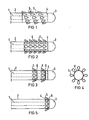
- 1 denotes the electrical conductor of an electrode. It is provided with electrical insulation 2.
- the electrode head 3 At the distal end is the electrode head 3, which is essentially cylindrical and is rounded at its free end. The head can also have other shapes, e.g. B. pure non-rounded cylindrical shape. Like. Have.
- the electrode head 3 At its rear end 4, the electrode head 3 is connected to the electrical conductor 1. After application of the electrode head 3 to the heart wall, 3 stimulation pulses can be supplied to the heart via conductor 1 and electrode head.
- loops 5 are provided in the vicinity of the electrode head, into which heart tissue can grow.
- the loops 5 are fixed in Fig. 1 on a collar 6 which is pushed onto the insulation 2.
- the loops 5 are attached along a helical line.
- the loops 5 are fastened on the collar 6 distributed around the circumference along parallel lines which run in the longitudinal direction of the elongated conductor 1.
- the electrode of FIG. 4 shows the collar 6 with loops 5 in a front view. This type of training enables punching out as a complete stamped part.
- the loops 5 can be made of a soft, thin resistive material, such as polyester or polypropylene.
- a resorbable material, such as catgut, can also be used for production, which dissolves over time when an electrode is implanted, so that an electrode replacement can be carried out without complications if required.
- the loops can be put on instead Collars can also be attached directly to the electrical insulation 2. They protrude the surface of the electrodes by about 1 to 5 mm. Because the loops 5 are made of a very soft and thin material, regardless of the number and size, they lie close to the electrode when the electrode is inserted into a vein. With the smallest diameter of the electrode there is hardly any resistance when inserting. Blood coagulum also collects in the loops when the electrode is inserted, which, as an adhesive, makes it easier for the electrode to stick to the heart wall.
Landscapes
- Health & Medical Sciences (AREA)
- Cardiology (AREA)
- Heart & Thoracic Surgery (AREA)
- Vascular Medicine (AREA)
- Engineering & Computer Science (AREA)
- Biomedical Technology (AREA)
- Nuclear Medicine, Radiotherapy & Molecular Imaging (AREA)
- Radiology & Medical Imaging (AREA)
- Life Sciences & Earth Sciences (AREA)
- Animal Behavior & Ethology (AREA)
- General Health & Medical Sciences (AREA)
- Public Health (AREA)
- Veterinary Medicine (AREA)
- Electrotherapy Devices (AREA)
Description
- Die Erfindung betrifft eine Endocard-Elektrodenanordnung für die intrakardiale Stimulation des Herzens, mit einem langgestreckten elektrischen Leiter, der mit einer elektrischen Isolierung versehen ist, und mit einem mit dem distalen Ende des Leiters elektrisch leitend verbundenen, für die Zuführung der Stimulationsimpulse zum Herzen dienenden Elektrodenkopf und mit Mitteln zum Fixieren des Leiters bzw. des Elektrodenkopfes an der Herzwand.
- Aus der US-Patentschrift 3 902 501 ist eine Endocard-Elektrode dieser Art bekannt. Als Fixiermittel dienen bei dieser Elektrode relativ steife Widerhaken aus Silicongummi unmittelbar hinter dem Elektrodenkopf, die nach Applikation ins Herzgewebe eingreifen und somit die Elektrode am Platz halten. Das Einführen einer solchen Elektrode in eine Vene, insbesondere mit einem kleinen Durchmesser, wie z.B. bei Kindern, bereitet jedoch wegen des relativ voluminösen Elektrodenkopfes nicht unerhebliche Schwierigkeiten. Bei vorhofgesteuerten Herzschrittmachern werden in der Regel sogar zwei Elektroden eingesetzt. Selbst bei Venen mit normal grossem Durchmesser sind zwei Elektrodenköpfe kaum noch plazierbar. Die Widerhaken erlauben auch kaum nachträgliche Korrekturen der Lage; ihr Anwuchs an die Herzwand ist erschwert, da sie dem Bindegewebe nur wenig Platz zum Umwachsen bieten.
- Der Erfindung liegt die Aufgabe zugrunde, eine Endocard-Elektrodenanordnung der eingangs genannten Art zu schaffen, die gut am Herzen anwächst und die dennoch ein verhältnismässig kleines Volumen hat.
- Diese Aufgabe ist erfindungsgemäss dadurch gelöst, dass zum Fixieren des Leiters bzw. des Elektrodenkopfes eine Schleife oder eine Mehrzahl solcher Schleifen aus weichem dünnem Material vorgesehen ist, die auf dem Elektrodenkopf oder auf der elektrischen Isolierung des langgestreckten elektrischen Leiters in der Nähe des Elektrodenkopfes befestigt ist.
- Schleifen aus einem weichen dünnen Material legen sich beim Einführen der Elektrode in eine Vene auch mit sehr kleinem Durchmesser dicht an die Elektrode an. Der Einführung wird also kaum Widerstand entgegengebracht. Die Flexibilität des Schleifenmaterials erlaubt darüber hinaus Ortskorrekturen beliebigerArt, ohne dass das Trabekel beschädigt wird. In die Schleifen wächst ausserdem rasch und leicht Bindegewebe hinein, so dass die Elektrode an der Herzwand gut fixiert wird. Ein weiterer Vorteil der Schleifen liegt darin, dass die Schleifen beim Durchführen der Elektrode durch eine Vene mit Blut-Koagulat gefüllt werden. Das Blut-Koagulat dient als Kleber, so dass die Schleifen an der Herzwand festgeklebt werden, was zu einem besonders raschen Festwachsen der Elektrode führt.
- Ein weiterer Vorteil ist darin zu sehen, dass die erfindungsgemässe Elektrode wegen ihres geringen Durchmessers bei einer Subclava-Punktion verwendet werden kann. Bei einer Subclava-Punktion wird ohne chirurgischen Schnitt ein Katheter kleinen Durchmessers durch die Subclava gestochen. Die Elektrode wird dann durch den Katheter in das Gefäss zum Herzen eingeführt.
- Eine vorteilhafte Weiterbildung der Erfindung besteht darin, dass die Schleifen aus einem resorbierbaren Material bestehen. Dadurch ist erreicht, dass die eingepflanzte Elektrode zu einem späteren Zeitpunkt sehr leicht zu entfernen ist, da die Schleifen sich mit der Zeit auflösen.
- Weitere Einzelheiten ergeben sich aus den Unteransprüchen.
- Die Erfindung ist anhand mehrerer in den Figuren dargestellter Ausführungsbeispiele näher erläutert.
- Es zeigen:
- Fig. 1 das distale Ende einer erfindungsgemässen Endocard-Elektrodenanordnung,
- Fig. 2 und 3 Varianten der Endocard-Elektrodenanordnung gemäss Fig. 1,
- Fig. 4 die Endocard-Elektrodenanordnung gemäss Fig. 3 in Vorderansicht,
- Fig. 5 eine Variante der Endocard-Elektrodenanordnung nach Fig. 3.
- In Fig. 1 ist mit 1 der elektrische Leiter einer Elektrode bezeichnet. Er ist mit einer elektrischen Isolierung 2 versehen. Am distalen Ende befindet sich der Elektrodenkopf 3, der im wesentlichen zylindrisch ausgebildet und an seinem freien Ende abgerundet ist. Der Kopf kann auch andere Formen, z. B. reine ungerundete Zylinderform od. dgl., aufweisen. An seinem hinteren Ende 4 ist der Elektrodenkopf 3 mit dem elektrischen Leiter 1 verbunden. Nach Applizieren des Elektrodenkopfes 3 an der Herzwand können dem Herzen über Leiter 1 und Elektrodenkopf 3 Stimulationsimpulse zugeführt werden.
- Damit die Elektrode an ihrem Platz im Herzen sicher gehalten wird, sind in der Nähe des Elektrodenkopfes Schleifen 5 vorgesehen, in die Herzgewebe einwachsen kann. Die Schleifen 5 sind in Fig. 1 auf einem Kragen 6, der auf die Isolierung 2 geschoben ist, befestigt. Hier sind die Schleifen 5 entlang einer wendelförmigen Linie angebracht.
- Bei der Elektrode der Fig. 2 sind die Schleifen 5 auf dem Kragen 6 am Umfang verteilt entlang paralleler Linien, die in der Längsrichtung des langgestreckten Leiters 1 verlaufen befestigt.
- Bei der Elektrode der Fig. 3 sind mehrere Kragen 6, die mit Schleifen 5 versehen sind, in Abstand voneinander auf die Isolierung 2 des Leiters 1 geschoben.
- Die Elektrode der Fig. 4 zeigt den Kragen 6 mit Schleifen 5 in Vorderansicht. Diese Art der Ausbildung ermöglicht Ausstanzen als komplettes Stanzteil.
- Die Elektrode der Fig. 5 zeigt eine Anordnung eines Kragens 6 mit Schleifen 5 auf dem Elektrodenkopf 3.
- Die Schleifen 5 können aus einem weichen dünnen resistiven Material, wie z.B. Polyester oder Polypropylen, gefertigt werden. Ebensogut kann zur Fertigung auch ein resorbierbares Material, wie z.B. Katgut, eingesetzt werden, das sich bei einer eingepflanzten Elektrode mit der Zeit auflöst, so dass ein Elektrodenaustausch bei Bedarf ohne Komplikationen möglich ist. Die Schleifen können anstelle auf Kragen auch direkt auf der elektrischen Isolierung 2 angebracht werden. Sie überragen die Oberfläche der Elektroden mit etwa 1 bis 5 mm. Dadurch, dass die Schleifen 5 aus einem sehr weichen und dünnen Material bestehen, liegen sie unabhängig von Anzahl und Grösse beim Einführen der Elektrode in eine Vene dicht an der Elektrode an. Bei kleinstem Durchmesser der Elektrode ergibt sich kaum Widerstand beim Einschieben. In den Schleifen sammelt sich beim Einführen der Elektrode auch Blut-Koagulat, das als Kleber das Festwachsen der Elektrode an der Herzwand erleichtert.
Claims (8)
Applications Claiming Priority (2)
| Application Number | Priority Date | Filing Date | Title |
|---|---|---|---|
| DE3015260 | 1980-04-21 | ||
| DE19803015260 DE3015260A1 (de) | 1980-04-21 | 1980-04-21 | Endocard-elektrodenanordnung |
Publications (2)
| Publication Number | Publication Date |
|---|---|
| EP0038484A1 EP0038484A1 (de) | 1981-10-28 |
| EP0038484B1 true EP0038484B1 (de) | 1983-12-14 |
Family
ID=6100552
Family Applications (1)
| Application Number | Title | Priority Date | Filing Date |
|---|---|---|---|
| EP81102709A Expired EP0038484B1 (de) | 1980-04-21 | 1981-04-09 | Endocard-Elektrodenanordnung |
Country Status (4)
| Country | Link |
|---|---|
| US (1) | US4407303A (de) |
| EP (1) | EP0038484B1 (de) |
| JP (1) | JPS56163662A (de) |
| DE (2) | DE3015260A1 (de) |
Cited By (3)
| Publication number | Priority date | Publication date | Assignee | Title |
|---|---|---|---|---|
| FR2579469A2 (fr) * | 1984-03-27 | 1986-10-03 | Atesys | Electrode pour les appareils de traitement des troubles du rythme cardiaque |
| EP0911058A1 (de) | 1997-10-21 | 1999-04-28 | Akzo Nobel N.V. | Sphärische Elektrode |
| US6162219A (en) * | 1997-10-21 | 2000-12-19 | Akzo Nobel N.V. | Electrode |
Families Citing this family (69)
| Publication number | Priority date | Publication date | Assignee | Title |
|---|---|---|---|---|
| US4628944A (en) * | 1982-02-08 | 1986-12-16 | Cordis Corporation | Cardiac pacing lead with biodegradable fixation structure |
| US4465079A (en) * | 1982-10-13 | 1984-08-14 | Medtronic, Inc. | Biomedical lead with fibrosis-inducing anchoring strand |
| DE3305271A1 (de) * | 1983-02-16 | 1984-08-16 | Siemens AG, 1000 Berlin und 8000 München | Elektrodenanordnung |
| US4550737A (en) * | 1983-10-12 | 1985-11-05 | Peter Osypka | Intravenously implantable electrode lead for use with cardiac pacemakers |
| FR2561929B1 (fr) * | 1984-03-27 | 1989-02-03 | Atesys | Appareillage automatique implante pour la defibrillation ventriculaire |
| DE3414072A1 (de) * | 1984-04-13 | 1985-10-17 | Siemens AG, 1000 Berlin und 8000 München | Endokardiale elektrodenanordnung |
| US4690148A (en) * | 1984-09-13 | 1987-09-01 | Cordis Corporation | Surface mapping electrode sets |
| US4620550A (en) * | 1985-04-15 | 1986-11-04 | Schering A.G. | Implantable bipolar stimulating electrode |
| US4716888A (en) * | 1985-06-17 | 1988-01-05 | Cordis Corporation | Tined leads |
| US4796643A (en) * | 1986-09-30 | 1989-01-10 | Telectronics N.V. | Medical electrode leads |
| US5052407A (en) * | 1988-04-14 | 1991-10-01 | Mieczyslaw Mirowski | Cardiac defibrillation/cardioversion spiral patch electrode |
| US4886065A (en) * | 1988-08-08 | 1989-12-12 | California Institute Of Technology | In vivo electrode implanting system |
| US4913164A (en) * | 1988-09-27 | 1990-04-03 | Intermedics, Inc. | Extensible passive fixation mechanism for lead assembly of an implantable cardiac stimulator |
| SE9202480D0 (sv) * | 1992-08-28 | 1992-08-28 | Siemens Elema Ab | Elektrodanordning |
| US5300107A (en) * | 1992-10-22 | 1994-04-05 | Medtronic, Inc. | Universal tined myocardial pacing lead |
| US5755767A (en) * | 1996-08-02 | 1998-05-26 | Pacesetter, Inc. | Anti-dislodgment and anti-perforation distal tip design for transvenous lead |
| US5782898A (en) * | 1996-10-15 | 1998-07-21 | Angeion Corporation | System for anchoring mid-lead electrode on an endocardial catheter lead |
| EP0911057A1 (de) | 1997-10-21 | 1999-04-28 | Akzo Nobel N.V. | Sphärische Elektrode |
| US5931864A (en) * | 1998-02-20 | 1999-08-03 | Cardiac Pacemakers, Inc. | Coronary venous lead having fixation mechanism |
| US6999819B2 (en) * | 2001-08-31 | 2006-02-14 | Medtronic, Inc. | Implantable medical electrical stimulation lead fixation method and apparatus |
| US20030105501A1 (en) * | 2001-12-03 | 2003-06-05 | Warman Eduardo N. | Shaped lead with electrodes |
| DE10331106A1 (de) * | 2003-07-04 | 2005-01-27 | Biotronik Meß- und Therapiegeräte GmbH & Co. Ingenieurbüro Berlin | Elektrodenleitung |
| US7343202B2 (en) * | 2004-02-12 | 2008-03-11 | Ndi Medical, Llc. | Method for affecting urinary function with electrode implantation in adipose tissue |
| US20080161874A1 (en) * | 2004-02-12 | 2008-07-03 | Ndi Medical, Inc. | Systems and methods for a trial stage and/or long-term treatment of disorders of the body using neurostimulation |
| US8467875B2 (en) | 2004-02-12 | 2013-06-18 | Medtronic, Inc. | Stimulation of dorsal genital nerves to treat urologic dysfunctions |
| ATE523221T1 (de) * | 2004-06-10 | 2011-09-15 | Medtronic Urinary Solutions Inc | Systeme und verfahren für die bilaterale stimulierung von linken und rechten ästen der dorsalen genitalnerven zur behandlung von funktionsstörungen, wie z.b. harninkontinenz |
| US7761167B2 (en) | 2004-06-10 | 2010-07-20 | Medtronic Urinary Solutions, Inc. | Systems and methods for clinician control of stimulation systems |
| US8195304B2 (en) | 2004-06-10 | 2012-06-05 | Medtronic Urinary Solutions, Inc. | Implantable systems and methods for acquisition and processing of electrical signals |
| US9205255B2 (en) | 2004-06-10 | 2015-12-08 | Medtronic Urinary Solutions, Inc. | Implantable pulse generator systems and methods for providing functional and/or therapeutic stimulation of muscles and/or nerves and/or central nervous system tissue |
| US7283867B2 (en) | 2004-06-10 | 2007-10-16 | Ndi Medical, Llc | Implantable system and methods for acquisition and processing of electrical signals from muscles and/or nerves and/or central nervous system tissue |
| US8165692B2 (en) | 2004-06-10 | 2012-04-24 | Medtronic Urinary Solutions, Inc. | Implantable pulse generator power management |
| US9308382B2 (en) | 2004-06-10 | 2016-04-12 | Medtronic Urinary Solutions, Inc. | Implantable pulse generator systems and methods for providing functional and/or therapeutic stimulation of muscles and/or nerves and/or central nervous system tissue |
| US8180462B2 (en) | 2006-04-18 | 2012-05-15 | Cyberonics, Inc. | Heat dissipation for a lead assembly |
| US9480846B2 (en) | 2006-05-17 | 2016-11-01 | Medtronic Urinary Solutions, Inc. | Systems and methods for patient control of stimulation systems |
| US8478420B2 (en) | 2006-07-12 | 2013-07-02 | Cyberonics, Inc. | Implantable medical device charge balance assessment |
| US20080027524A1 (en) | 2006-07-26 | 2008-01-31 | Maschino Steven E | Multi-electrode assembly for an implantable medical device |
| US7974707B2 (en) | 2007-01-26 | 2011-07-05 | Cyberonics, Inc. | Electrode assembly with fibers for a medical device |
| US8868203B2 (en) * | 2007-10-26 | 2014-10-21 | Cyberonics, Inc. | Dynamic lead condition detection for an implantable medical device |
| US8942798B2 (en) * | 2007-10-26 | 2015-01-27 | Cyberonics, Inc. | Alternative operation mode for an implantable medical device based upon lead condition |
| US8478428B2 (en) | 2010-04-23 | 2013-07-02 | Cyberonics, Inc. | Helical electrode for nerve stimulation |
| EP2974016B1 (de) | 2013-03-15 | 2019-03-06 | Alfred E. Mann Foundation for Scientific Research | Strommessung mit mehreren ausgangsstromstimulatoren mit schneller einschaltzeit |
| WO2015017475A2 (en) | 2013-07-29 | 2015-02-05 | Alfred E. Mann Foundation For Scientific Research | Microprocessor controlled class e driver |
| US10004913B2 (en) | 2014-03-03 | 2018-06-26 | The Board Of Trustees Of The Leland Stanford Junior University | Methods and apparatus for power conversion and data transmission in implantable sensors, stimulators, and actuators |
| US9669210B2 (en) * | 2014-04-22 | 2017-06-06 | Boston Scientific Neuromodulation Corporation | Electrical stimulation leads and systems with folding anchoring units and methods of making and using |
| US10434329B2 (en) | 2014-05-09 | 2019-10-08 | The Board Of Trustees Of The Leland Stanford Junior University | Autofocus wireless power transfer to implantable devices in freely moving animals |
| US9649489B2 (en) | 2014-06-02 | 2017-05-16 | Boston Scientific Neuromodulation Corporation | Electrical stimulation leads and systems with anchoring units having struts and methods of making and using |
| CN107148294B (zh) | 2014-08-15 | 2021-08-24 | 艾克索尼克斯股份有限公司 | 用于试验神经刺激的外部脉冲发生器设备和相关联方法 |
| US9555246B2 (en) | 2014-08-15 | 2017-01-31 | Axonics Modulation Technologies, Inc. | Electromyographic lead positioning and stimulation titration in a nerve stimulation system for treatment of overactive bladder |
| JP6878269B2 (ja) | 2014-08-15 | 2021-05-26 | アクソニクス モジュレーション テクノロジーズ インコーポレイテッド | 神経位置特定に基づく神経刺激電極構成のためのシステムおよび方法 |
| CA2958210C (en) | 2014-08-15 | 2023-09-26 | Axonics Modulation Technologies, Inc. | Integrated electromyographic clinician programmer for use with an implantable neurostimulator |
| US9802038B2 (en) | 2014-08-15 | 2017-10-31 | Axonics Modulation Technologies, Inc. | Implantable lead affixation structure for nerve stimulation to alleviate bladder dysfunction and other indication |
| CN107427685B (zh) | 2015-01-09 | 2021-09-21 | 艾克索尼克斯股份有限公司 | 与神经刺激充电设备一起使用的附接设备及相关联方法 |
| ES2729702T3 (es) | 2015-01-09 | 2019-11-05 | Axonics Modulation Tech Inc | Antena mejorada y procedimientos de uso para un estimulador nervioso implantable |
| WO2016112398A1 (en) | 2015-01-09 | 2016-07-14 | Axonics Modulation Technologies, Inc. | Patient remote and associated methods of use with a nerve stimulation system |
| EP3319683A4 (de) | 2015-07-10 | 2018-12-26 | Axonics Modulation Technologies, Inc. | Implantierbarer nervenstimulator mit interner elektronik ohne asic und verfahren zur verwendung |
| WO2017044904A1 (en) | 2015-09-11 | 2017-03-16 | Nalu Medical, Inc. | Apparatus for peripheral or spinal stimulation |
| WO2017132374A1 (en) | 2016-01-29 | 2017-08-03 | Axonics Modulation Technologies, Inc. | Methods and systems for frequency adjustment to optimize charging of implantable neurostimulator |
| CA3014195A1 (en) | 2016-02-12 | 2017-08-17 | Axonics Modulation Technologies, Inc. | External pulse generator device and associated methods for trial nerve stimulation |
| EP4395124A3 (de) | 2016-03-21 | 2024-07-31 | Nalu Medical, Inc. | Vorrichtungen und verfahren zur positionierung externer vorrichtungen in bezug auf implantierte vorrichtungen |
| EP3484577B1 (de) | 2016-07-18 | 2025-06-18 | Nalu Medical, Inc. | Systeme zur behandlung von beckenerkrankungen und schmerzzuständen |
| EP3585475B1 (de) | 2017-02-24 | 2024-04-03 | Nalu Medical, Inc. | Vorrichtung mit sequentiell implantierten stimulatoren |
| AU2018265016B2 (en) | 2017-05-09 | 2023-01-05 | Nalu Medical, Inc. | Stimulation apparatus |
| EP3755418B1 (de) | 2018-02-22 | 2023-06-21 | Axonics, Inc. | Nervenstimulationselektroden für nervenstimulationstests |
| WO2020185902A1 (en) | 2019-03-11 | 2020-09-17 | Axonics Modulation Technologies, Inc. | Charging device with off-center coil |
| US11439829B2 (en) | 2019-05-24 | 2022-09-13 | Axonics, Inc. | Clinician programmer methods and systems for maintaining target operating temperatures |
| WO2020242900A1 (en) | 2019-05-24 | 2020-12-03 | Axonics Modulation Technologies, Inc. | Trainer device for a neurostimulator programmer and associated methods of use with a neurostimulation system |
| EP3993866A4 (de) | 2019-07-02 | 2023-07-12 | Nalu Medical, Inc. | Stimulationsvorrichtung |
| US12420103B1 (en) | 2020-08-20 | 2025-09-23 | Axonics, Inc. | Neurostimulation leads with reduced current leakage |
| RU2766402C1 (ru) * | 2021-07-23 | 2022-03-15 | Сергей Петрович Семитко | Эндокардиальный электрод для временной трансвенозной электрокардиостимуляции |
Family Cites Families (12)
| Publication number | Priority date | Publication date | Assignee | Title |
|---|---|---|---|---|
| BE656915A (de) * | 1964-12-10 | |||
| FR2122032A5 (de) * | 1971-01-15 | 1972-08-25 | Rhone Poulenc Sa | |
| US3737579A (en) * | 1971-04-19 | 1973-06-05 | Medtronic Inc | Body tissue electrode and device for screwing the electrode into body tissue |
| US3902501A (en) * | 1973-06-21 | 1975-09-02 | Medtronic Inc | Endocardial electrode |
| DE2461370A1 (de) * | 1974-01-02 | 1975-07-03 | Sauvage Lester R | Poroese vaskulaere prothese |
| US4026303A (en) * | 1975-11-17 | 1977-05-31 | Vitatron Medical B.V. | Endocardial pacing electrode |
| DE2613086B2 (de) * | 1976-03-26 | 1979-10-11 | Siemens Ag, 1000 Berlin Und 8000 Muenchen | Endocardelektrode |
| US4156429A (en) * | 1977-10-11 | 1979-05-29 | Cardiac Pacemakers, Inc. | Implantable electrode |
| FR2423231A1 (fr) * | 1978-04-19 | 1979-11-16 | Synthelabo | Sonde de stimulation cardiaque endocavitaire |
| EP0009732A1 (de) * | 1978-10-06 | 1980-04-16 | Precimed S.A. | Katheter für Herzschrittmacher |
| DE2922354A1 (de) * | 1979-06-01 | 1980-12-11 | Bisping Hans Juergen | Transvenoese herzschrittmacher-elektrode |
| US4301815A (en) * | 1980-01-23 | 1981-11-24 | Telectronics Pty. Limited | Trailing tine electrode lead |
-
1980
- 1980-04-21 DE DE19803015260 patent/DE3015260A1/de not_active Withdrawn
-
1981
- 1981-04-09 US US06/252,428 patent/US4407303A/en not_active Expired - Lifetime
- 1981-04-09 DE DE8181102709T patent/DE3161622D1/de not_active Expired
- 1981-04-09 EP EP81102709A patent/EP0038484B1/de not_active Expired
- 1981-04-20 JP JP5962281A patent/JPS56163662A/ja active Pending
Cited By (3)
| Publication number | Priority date | Publication date | Assignee | Title |
|---|---|---|---|---|
| FR2579469A2 (fr) * | 1984-03-27 | 1986-10-03 | Atesys | Electrode pour les appareils de traitement des troubles du rythme cardiaque |
| EP0911058A1 (de) | 1997-10-21 | 1999-04-28 | Akzo Nobel N.V. | Sphärische Elektrode |
| US6162219A (en) * | 1997-10-21 | 2000-12-19 | Akzo Nobel N.V. | Electrode |
Also Published As
| Publication number | Publication date |
|---|---|
| DE3161622D1 (en) | 1984-01-19 |
| EP0038484A1 (de) | 1981-10-28 |
| JPS56163662A (en) | 1981-12-16 |
| DE3015260A1 (de) | 1981-10-22 |
| US4407303A (en) | 1983-10-04 |
Similar Documents
| Publication | Publication Date | Title |
|---|---|---|
| EP0038484A1 (de) | Endocard-Elektrodenanordnung | |
| DE69627290T2 (de) | Implantierbares Elektrodenkabel mit mindestens einem Elektrodenkontakt | |
| DE69029564T2 (de) | Geflochtene Elektrodenleitungen und Katheter für ihre Benutzung | |
| EP3369368B1 (de) | Multi-elektroden anordnung | |
| DE4335098B4 (de) | Elektrodenzuleitung mit Halteelement für einen Führungsstab und deren Verwendung | |
| US10398890B2 (en) | Introduction of medical lead into patient | |
| DE69205980T2 (de) | Zeitliche herzleitung. | |
| DE2918741C2 (de) | In den rechten Vorhof des Herzens transvenös einführbarer Katheter mit verschiebbarem Draht | |
| US4488561A (en) | Pacing lead with insertable memory coil | |
| DE69213336T2 (de) | Werkzeug zur Einführung und Tunnelung für subkutane Drahtgeflecht-Elektroden | |
| DE69319789T2 (de) | Elektrodenanordnung | |
| EP3074083B1 (de) | Vorrichtung zur transkutanen implantation epikardialer herzschrittmacherelektroden | |
| DE2219044A1 (de) | In Körpergewebe einschraubbare Elektrodenanordnung | |
| DE2652195A1 (de) | Schrittmacherelektrode | |
| DE7504819U (de) | Mit einem elektrischen leiter ausgeruestete implantable elektrode | |
| DE1764790A1 (de) | In den lebenden Koerper einpflanzbare Elektroden | |
| DE8207842U1 (de) | Implantierbare leitung | |
| EP0159540A1 (de) | Chirurgische Elektrode | |
| DE2539553A1 (de) | Elektrodenanordnung fuer medizinische zwecke | |
| EP2747835A1 (de) | Implantierbare epikardiale elektroden anordnung | |
| DE2737787A1 (de) | Elektrode | |
| DE19781819B4 (de) | Kardiale Schrittmacher-Anschlußvorrichtung | |
| EP2110154B1 (de) | Vorrichtung zur Reduktion der Störungsanfälligkeit für langgestreckte Implantate | |
| EP2143464A2 (de) | Implantierbare Elektrodenleitung oder Elektrodenleitungsanordnung | |
| DE2533766A1 (de) | Transvenoese, implantierbare herzschrittmacherelektrode |
Legal Events
| Date | Code | Title | Description |
|---|---|---|---|
| PUAI | Public reference made under article 153(3) epc to a published international application that has entered the european phase |
Free format text: ORIGINAL CODE: 0009012 |
|
| AK | Designated contracting states |
Designated state(s): DE FR NL SE |
|
| 17P | Request for examination filed |
Effective date: 19811028 |
|
| GRAA | (expected) grant |
Free format text: ORIGINAL CODE: 0009210 |
|
| AK | Designated contracting states |
Designated state(s): DE FR NL SE |
|
| REF | Corresponds to: |
Ref document number: 3161622 Country of ref document: DE Date of ref document: 19840119 |
|
| ET | Fr: translation filed | ||
| PLBE | No opposition filed within time limit |
Free format text: ORIGINAL CODE: 0009261 |
|
| STAA | Information on the status of an ep patent application or granted ep patent |
Free format text: STATUS: NO OPPOSITION FILED WITHIN TIME LIMIT |
|
| 26N | No opposition filed | ||
| PGFP | Annual fee paid to national office [announced via postgrant information from national office to epo] |
Ref country code: DE Payment date: 19900625 Year of fee payment: 10 |
|
| PGFP | Annual fee paid to national office [announced via postgrant information from national office to epo] |
Ref country code: SE Payment date: 19910423 Year of fee payment: 11 Ref country code: FR Payment date: 19910423 Year of fee payment: 11 |
|
| PGFP | Annual fee paid to national office [announced via postgrant information from national office to epo] |
Ref country code: NL Payment date: 19910430 Year of fee payment: 11 |
|
| PG25 | Lapsed in a contracting state [announced via postgrant information from national office to epo] |
Ref country code: DE Effective date: 19920201 |
|
| PG25 | Lapsed in a contracting state [announced via postgrant information from national office to epo] |
Ref country code: SE Effective date: 19920410 |
|
| PG25 | Lapsed in a contracting state [announced via postgrant information from national office to epo] |
Ref country code: NL Effective date: 19921101 |
|
| NLV4 | Nl: lapsed or anulled due to non-payment of the annual fee | ||
| PG25 | Lapsed in a contracting state [announced via postgrant information from national office to epo] |
Ref country code: FR Effective date: 19921230 |
|
| REG | Reference to a national code |
Ref country code: FR Ref legal event code: ST |
|
| EUG | Se: european patent has lapsed |
Ref document number: 81102709.3 Effective date: 19921108 |