EP0038155B1 - An improved bed or the like - Google Patents
An improved bed or the like Download PDFInfo
- Publication number
- EP0038155B1 EP0038155B1 EP81301481A EP81301481A EP0038155B1 EP 0038155 B1 EP0038155 B1 EP 0038155B1 EP 81301481 A EP81301481 A EP 81301481A EP 81301481 A EP81301481 A EP 81301481A EP 0038155 B1 EP0038155 B1 EP 0038155B1
- Authority
- EP
- European Patent Office
- Prior art keywords
- bed
- members
- support surface
- spaced
- transversely extending
- Prior art date
- Legal status (The legal status is an assumption and is not a legal conclusion. Google has not performed a legal analysis and makes no representation as to the accuracy of the status listed.)
- Expired
Links
Images

Classifications
-
- A—HUMAN NECESSITIES
- A47—FURNITURE; DOMESTIC ARTICLES OR APPLIANCES; COFFEE MILLS; SPICE MILLS; SUCTION CLEANERS IN GENERAL
- A47C—CHAIRS; SOFAS; BEDS
- A47C23/00—Spring mattresses with rigid frame or forming part of the bedstead, e.g. box springs; Divan bases; Slatted bed bases
- A47C23/06—Spring mattresses with rigid frame or forming part of the bedstead, e.g. box springs; Divan bases; Slatted bed bases using wooden springs, e.g. of slat type ; Slatted bed bases
- A47C23/062—Slat supports
- A47C23/065—Slat supports by fluid means
Definitions
- the present invention relates to support appliances such as beds, chairs or couches designed to provide a high standard or comfort for all types of user, large or small, heavy or light in weight, or to sufferers from back complaints.
- appliances such as beds, chairs or couches designed to provide a high standard or comfort for all types of user, large or small, heavy or light in weight, or to sufferers from back complaints.
- bed or the like will be used generally to describe all such appliances.
- DE-B-2621803 discloses a bed having spaced, longitudinally extending rigid members each accommodating a closed elongate resilient tube which is pressurised to meet the requirements of the person using the bed.
- the upper surface of each tube has a plurality of spaced pockets vulcanised thereto with the pockets of one tube all facing towards the pockets of the other tube.
- the body support surface of the bed is formed by a plurality of transversely extending, laminated slats arranged parallel to each other with their ends fixedly mounted in the tube pockets.
- FR-A-2407692 discloses a bed having spaced, longitudinally extending body elements each provided with a plurality of upstanding longitudinally aligned elastomeric blocks.
- the body support surface of the bed is formed by a plurality of transversely extending slats arranged parallel to each other with their ends supported by the elastomeric blocks and slidably mounted in vertical guides.
- present practice is for users to purchase beds having soft, medium or hard mattresses and once purchased, there is no adjustment possible. Guests and casual users may therefore experience some discomfort and even detrimental after effects e.g. back complaints, for some time after use. Therefore, it is also an object of this invention to provide a means whereby users of such beds, whether having back troubles or not, have the ability to rapidly adjust the bed to the exact desired hardness or softness required by the user. For example, in the case of a so-called double bed, the user of one side might be light in weight and require a more resilient (softer) surface to lie on, whereas the other user may be of heavier build and require a firmer surface in order to compensate for the increased weight.
- the present invention enables both parties to have equal comfort by setting the resilience of the surface beforehand to their respective requirements, notwithstanding that each adjacent support surface was identically produced.
- the mattress used was a compromise hardness or softness which was often not suitable for either user.
- Single or double beds manufactured in a like, exact manner with final adjustment easily effected by the purchaser thus substantially reduces manufacturing costs by standardisation of all the main components.
- the present invention consists in a bed or the like comprising a frame and a body support surface formed by a plurality of members extending transversely of the frame, said members being guided for movement normal to the plane of the body support surface with spaced portions of each member positioned, respectively, on opposite sides of its centre and the portions of the members positioned on the same side of the centre all resting on a common pressurised, flexible elongate tube such that, in use, the support surface formed by the transversely extending members, when viewed from the side of the bed, conforms substantially to the profile of a user's body supported by said support surface, characterised in that said spaced portions of each member rest on, without connection to, the associated elongate tubes.
- each side member 12 has its lower portion of channel-shaped cross-section which is formed by an inwardly directed flange 14 provided at its inner end with an upwardly directed flange 16, spaced from, but parallel to the side member 12 with an elongate flexible tube 18 accommodated in the channel-shaped portion, the tube 18 having a filling valve 19 and containing air or liquid under pressure e.g. 1 to 5 Ibs/sq. inch depending on the weight and configuration of the users.
- a plurality of independent, transversely extending body support members or slats 20 extend between the side members 12 and are guided for vertical movement in guideways 22, conveniently formed by slots in the side members 12 which engage the respective extremities of each slat 20.
- a downwardly depending support foot 21 is fixedly mounted at each corner of the bed frame 10.
- each slat 20 may be formed with a downwardly extending portion 20a which engages with the respective pressurised tube 18 positioned along each side member 12 as described above.
- the lower surface 20b of each downwardly projecting portion 20a may be arcuate, or part-spherical, whilst the upper surface 20c of each slat 20 is preferably profiled to suit the user.
- the upper surfaces of all the slats 20 may be flat as shown in Fig. 2, or concave as shown in Fig.
- the upper surfaces of the slats 20 may collectively be formed to provide humps or ridges (not shown) in order to provide varying degrees of lumbar support so that a wide variety of users of different physique can receive the benefits of the bed construction in a simple and economical manner.
- the slats 20 enable the support surface to conform accurately to the profile of the user's body in contact with the support surface so that all parts are adequately supported i.e. the end portions of slats 20 subjected to the greatest pressure are thrust downwardly onto the pressurised tubes 18 to urge any non-pressurised slats upwardly into contact with the user's body.
- a thin foam mattress 23 may be provided to overlie the slats 20 and the bed may be provided with covers which are tailored to fit and provided with zips to allow easy removal thereof for laundering.
- a rectangular bed frame having longitudinally extending side members 12 and transverse end members (not shown) as described with reference to the previous embodiment.
- Each side member 12 has at its lower portion an inwardly directed flange 14 provided at its inner end with an upwardly directed member 16 having a plurality of aligned, vertical bores 24 extending therethrough.
- the member 16 is spaced from and parallel to the side member 12 with an elongate flexible tube 18 seated on the flange 14.
- the plurality of independent, transversely extending body support members or slats 20 are positioned with their larger dimension horizontally disposed and forming the body support surface.
- Each member 20 is guided for vertical movement by means of spaced downwardly depending dowels 26 fixedly mounted on the underside of the member 20 and slidable in the bores 24 in the respective upwardly directed members 16.
- dowels 26 fixedly mounted on the underside of the member 20 and slidable in the bores 24 in the respective upwardly directed members 16.
- the side members 12 are mounted on longitudinally extending support feet 28 positioned inwardly of the side members 12.
- a mattress or cover 23 may overlie the body support surface formed by the members or slats 20.
- a central, longitudinally extending member 30 is positioned at a level lower than the side members 12 and provides a common support for the adjacent flanges 14 and the associated upwardly extending flanges 16. It will be appreciated that this arrangement obviates a central ridge extending longitudinally of the bed as would be caused by the arrangement shown in Figs. 1 to 3 and as shown in Figure 6, enables the respective adjacent inner portions 20d, 20f of the members 20 to be in juxtaposed relationship and thus provide a "merging" of the two independent body support surfaces.
- Fig. 7 which shows a modification of the arrangement shown in Figure 4, the downwardly depending dowels 26 are slidable in bearing bushes 32 fixedly mounted in a panel 34 interconnecting the respective inwardly directed flanges 14.
- the lower end of each downwardly depending dowel 26 is provided with a part-spherical member 36 engaging the resilient tube 18 which, in this modified arrangement, is accommodated in a base member 38.
- Abutment members 40 may be provided to limit the vertical movement of the transversely extending members 20.
- the slats 20 may be of wood or moulded from a synthetic resinous material.
- a bed according to the present invention has the advantage that it is of normal shape, as opposed to a number of previous designs of orthopaedic, or other types of bed which tend to be of unusual shape, thus requiring special bed clothes and other covers.
- the basic frame and assembly may be utilised in place of a deep spring or other mattress, on top of the existing base in order to conveniently convert existing beds into the improved construction described above.
- beds made according to the present invention may conveniently be supplied in kit form which facilitates transit. Such beds are provided with connector members which simplifies re-assembly.
Landscapes
- Invalid Beds And Related Equipment (AREA)
- Mattresses And Other Support Structures For Chairs And Beds (AREA)
- Massaging Devices (AREA)
- Special Chairs (AREA)
- Addition Polymer Or Copolymer, Post-Treatments, Or Chemical Modifications (AREA)
- Materials For Medical Uses (AREA)
- Organic Low-Molecular-Weight Compounds And Preparation Thereof (AREA)
- Chemical Or Physical Treatment Of Fibers (AREA)
Abstract
Description
- The present invention relates to support appliances such as beds, chairs or couches designed to provide a high standard or comfort for all types of user, large or small, heavy or light in weight, or to sufferers from back complaints. For the purpose of this specification the term "bed or the like" will be used generally to describe all such appliances.
- Normally, persons suffering from back trouble require beds that furnish a large amount of lumbar support, which the ordinary resilient mattress does not provide. A known remedy is either to provide a special, hard mattress or to insert a rigid board between the mattress and the sprung bed. It will be readily appreciated that, although this treatment is effective, it is also somewhat uncomfortable as the increased support is also applied to other parts of the body where no such support is required, and where the additional support may even be undesirable.
- DE-B-2621803 (EGGENWEILER) discloses a bed having spaced, longitudinally extending rigid members each accommodating a closed elongate resilient tube which is pressurised to meet the requirements of the person using the bed. The upper surface of each tube has a plurality of spaced pockets vulcanised thereto with the pockets of one tube all facing towards the pockets of the other tube. The body support surface of the bed is formed by a plurality of transversely extending, laminated slats arranged parallel to each other with their ends fixedly mounted in the tube pockets.
- This prior art arrangement is complicated and costly due to the vulcanising of the pockets to the tubes which, in addition, increases the possibility of failure at the seams of each pocket.
- FR-A-2407692 (INDUSTRIE DE TRANSFORMATION DU BOIS) discloses a bed having spaced, longitudinally extending body elements each provided with a plurality of upstanding longitudinally aligned elastomeric blocks. The body support surface of the bed is formed by a plurality of transversely extending slats arranged parallel to each other with their ends supported by the elastomeric blocks and slidably mounted in vertical guides.
- This known arrangement is extremely costly due to the necessity of providing a pair of elastomeric blocks for each slat with the possibility of the blocks being of varying heights and resilience.
- It is an object of the present invention to provide a bed which provides adjustable increased lumbar support without sacrificing resilience of the bed in the region of the shoulders and the pelvis of the user.
- Furthermore, present practice is for users to purchase beds having soft, medium or hard mattresses and once purchased, there is no adjustment possible. Guests and casual users may therefore experience some discomfort and even detrimental after effects e.g. back complaints, for some time after use. Therefore, it is also an object of this invention to provide a means whereby users of such beds, whether having back troubles or not, have the ability to rapidly adjust the bed to the exact desired hardness or softness required by the user. For example, in the case of a so-called double bed, the user of one side might be light in weight and require a more resilient (softer) surface to lie on, whereas the other user may be of heavier build and require a firmer surface in order to compensate for the increased weight. The present invention enables both parties to have equal comfort by setting the resilience of the surface beforehand to their respective requirements, notwithstanding that each adjacent support surface was identically produced. Previously the mattress used was a compromise hardness or softness which was often not suitable for either user. Single or double beds manufactured in a like, exact manner with final adjustment easily effected by the purchaser thus substantially reduces manufacturing costs by standardisation of all the main components.
- Accordingly, the present invention consists in a bed or the like comprising a frame and a body support surface formed by a plurality of members extending transversely of the frame, said members being guided for movement normal to the plane of the body support surface with spaced portions of each member positioned, respectively, on opposite sides of its centre and the portions of the members positioned on the same side of the centre all resting on a common pressurised, flexible elongate tube such that, in use, the support surface formed by the transversely extending members, when viewed from the side of the bed, conforms substantially to the profile of a user's body supported by said support surface, characterised in that said spaced portions of each member rest on, without connection to, the associated elongate tubes.
- In the accompanying drawings in which like reference numerals have been used throughout the various Figures to designate similar or corresponding members:-
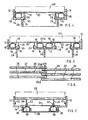
- Fig. 1 is a plan view of a bed according to the present invention,
- Fig. 2 is a cross-section, on an enlarged scale, taken along the line 2-2 of Fig. 1,
- Fig. 3 is a view, similar to Fig. 2, but showing a slightly modified construction,
- Fig. 4 is a cross-section of a second embodiment of a single bed according to the present invention,
- Fig. 5 is a cross-section similar to Fig. 4, but showing a double bed arrangement,
- Fig. 6 is a plan view showing a portion of the body support surface, and
- Fig. 7 is a cross-section, similar to Fig. 4, but showing a modified construction.
- In carrying the invention into effect according to one convenient mode, by way of example, there is provided a
rectangular bed frame 10 having longitudinally extendingside members 12 andtransverse end members 13. As shown in Fig. 2, eachside member 12 has its lower portion of channel-shaped cross-section which is formed by an inwardly directedflange 14 provided at its inner end with an upwardly directedflange 16, spaced from, but parallel to theside member 12 with an elongateflexible tube 18 accommodated in the channel-shaped portion, thetube 18 having afilling valve 19 and containing air or liquid under pressure e.g. 1 to 5 Ibs/sq. inch depending on the weight and configuration of the users. - A plurality of independent, transversely extending body support members or
slats 20 extend between theside members 12 and are guided for vertical movement inguideways 22, conveniently formed by slots in theside members 12 which engage the respective extremities of eachslat 20. A downwardly depending supportfoot 21 is fixedly mounted at each corner of thebed frame 10. - As shown in Fig. 3, the end portions of each
slat 20 may be formed with a downwardly extendingportion 20a which engages with the respectivepressurised tube 18 positioned along eachside member 12 as described above. To avoid chafing, thelower surface 20b of each downwardly projectingportion 20a may be arcuate, or part-spherical, whilst theupper surface 20c of eachslat 20 is preferably profiled to suit the user. In general, the upper surfaces of all theslats 20 may be flat as shown in Fig. 2, or concave as shown in Fig. 3 to form a longitudinally extending, concave, body support surface, so that the user is directed towards the centre of the bed, but if necessary, the upper surfaces of theslats 20 may collectively be formed to provide humps or ridges (not shown) in order to provide varying degrees of lumbar support so that a wide variety of users of different physique can receive the benefits of the bed construction in a simple and economical manner. - It will be seen that when a user lies on the bed, the
slats 20 enable the support surface to conform accurately to the profile of the user's body in contact with the support surface so that all parts are adequately supported i.e. the end portions ofslats 20 subjected to the greatest pressure are thrust downwardly onto the pressurisedtubes 18 to urge any non-pressurised slats upwardly into contact with the user's body. - If desired, a
thin foam mattress 23 may be provided to overlie theslats 20 and the bed may be provided with covers which are tailored to fit and provided with zips to allow easy removal thereof for laundering. - In the embodiment of the invention shown in Figure 4, there is provided a rectangular bed frame having longitudinally extending
side members 12 and transverse end members (not shown) as described with reference to the previous embodiment. Eachside member 12 has at its lower portion an inwardly directedflange 14 provided at its inner end with an upwardly directedmember 16 having a plurality of aligned,vertical bores 24 extending therethrough. Themember 16 is spaced from and parallel to theside member 12 with an elongateflexible tube 18 seated on theflange 14. - In this embodiment, the plurality of independent, transversely extending body support members or
slats 20 are positioned with their larger dimension horizontally disposed and forming the body support surface. Eachmember 20 is guided for vertical movement by means of spaced downwardly dependingdowels 26 fixedly mounted on the underside of themember 20 and slidable in thebores 24 in the respective upwardly directedmembers 16. Thus, in this embodiment, it is not necessary to have the extremities of themembers 20 guided for vertical movement in therespective side members 12, a similar guiding effect being provided by thedowels 26 sliding in theirrespective bores 24 in themembers 20, the respective end portions of which are supported by thetubes 18. Theside members 12 are mounted on longitudinally extendingsupport feet 28 positioned inwardly of theside members 12. A mattress orcover 23 may overlie the body support surface formed by the members orslats 20. - As shown in Figures 5 and 6, the construction described with reference to Figure 4 is particularly advantageous for double or king size beds. Thus, in a double bed construction, a central, longitudinally extending
member 30 is positioned at a level lower than theside members 12 and provides a common support for theadjacent flanges 14 and the associated upwardly extendingflanges 16. It will be appreciated that this arrangement obviates a central ridge extending longitudinally of the bed as would be caused by the arrangement shown in Figs. 1 to 3 and as shown in Figure 6, enables the respective adjacentinner portions 20d, 20f of themembers 20 to be in juxtaposed relationship and thus provide a "merging" of the two independent body support surfaces. - In Fig. 7 which shows a modification of the arrangement shown in Figure 4, the downwardly depending
dowels 26 are slidable inbearing bushes 32 fixedly mounted in a panel 34 interconnecting the respective inwardly directedflanges 14. In this construction, the lower end of each downwardly dependingdowel 26 is provided with a part-spherical member 36 engaging theresilient tube 18 which, in this modified arrangement, is accommodated in abase member 38.Abutment members 40 may be provided to limit the vertical movement of the transversely extendingmembers 20. - The
slats 20 may be of wood or moulded from a synthetic resinous material. - A bed according to the present invention has the advantage that it is of normal shape, as opposed to a number of previous designs of orthopaedic, or other types of bed which tend to be of unusual shape, thus requiring special bed clothes and other covers.
- Also, the basic frame and assembly may be utilised in place of a deep spring or other mattress, on top of the existing base in order to conveniently convert existing beds into the improved construction described above.
- A further advantage is that beds made according to the present invention may conveniently be supplied in kit form which facilitates transit. Such beds are provided with connector members which simplifies re-assembly.
Claims (10)
Priority Applications (1)
| Application Number | Priority Date | Filing Date | Title |
|---|---|---|---|
| AT81301481T ATE8569T1 (en) | 1980-04-11 | 1981-04-06 | BED OR LIKE. |
Applications Claiming Priority (2)
| Application Number | Priority Date | Filing Date | Title |
|---|---|---|---|
| GB8012121 | 1980-04-11 | ||
| GB8012121 | 1980-04-11 |
Publications (2)
| Publication Number | Publication Date |
|---|---|
| EP0038155A1 EP0038155A1 (en) | 1981-10-21 |
| EP0038155B1 true EP0038155B1 (en) | 1984-07-25 |
Family
ID=10512756
Family Applications (1)
| Application Number | Title | Priority Date | Filing Date |
|---|---|---|---|
| EP81301481A Expired EP0038155B1 (en) | 1980-04-11 | 1981-04-06 | An improved bed or the like |
Country Status (6)
| Country | Link |
|---|---|
| EP (1) | EP0038155B1 (en) |
| AT (1) | ATE8569T1 (en) |
| DE (1) | DE3164986D1 (en) |
| DK (1) | DK162281A (en) |
| FI (1) | FI811117L (en) |
| NO (1) | NO811243L (en) |
Cited By (4)
| Publication number | Priority date | Publication date | Assignee | Title |
|---|---|---|---|---|
| DE9213403U1 (en) * | 1992-10-06 | 1993-05-06 | Neumann, Hans-Joachim, 8949 Stetten | Lying surface of a sleeping system |
| DE19804362B4 (en) * | 1998-02-04 | 2007-08-02 | Woodstock Company Langegger Breitfuss Oeg | Pad for lying or sitting |
| DE102007030667A1 (en) | 2007-07-02 | 2009-01-08 | Recticel Schlafkomfort Gmbh | Support structure for a mattress |
| DE202008002110U1 (en) | 2008-01-11 | 2009-06-25 | Recticel Schlafkomfort Gmbh | Support structure for a mattress |
Families Citing this family (15)
| Publication number | Priority date | Publication date | Assignee | Title |
|---|---|---|---|---|
| NL8200401A (en) * | 1982-02-03 | 1983-09-01 | Auping Bv | BODY SUPPORT. |
| GB2164550B (en) * | 1984-09-20 | 1989-01-11 | Griffin G D | An improved body support arrangement |
| DE3505644A1 (en) * | 1985-02-19 | 1986-08-21 | Metalegno Stabilimento, Vaduz | Slatted support for double beds |
| DE3728408A1 (en) * | 1987-08-26 | 1989-03-09 | Oswald Kurt | BED |
| EP0354271A3 (en) * | 1988-08-12 | 1990-06-06 | Hcm Ag | Mattress |
| FR2641454A1 (en) * | 1989-01-09 | 1990-07-13 | Pierre Elmalek | SOMMIER AND METHOD FOR MANUFACTURING SOMMIER |
| DE69008726T2 (en) * | 1990-10-16 | 1994-10-27 | Complete Investments Ltd | Support device for the slats of a slatted frame. |
| US5070560A (en) * | 1990-10-22 | 1991-12-10 | Healthflex, Inc. | Pressure relief support system for a mattress |
| EP0489374A1 (en) * | 1990-12-06 | 1992-06-10 | Reinhard Hörburger | Slat support for mattresses and the like |
| DE4331240A1 (en) * | 1993-09-15 | 1995-03-16 | Erhard Dr Weber | Pneumatic, resilient surface bearing and its uses |
| DE19811854B4 (en) | 1998-03-18 | 2007-04-12 | Woodstock Company Langegger Breitfuss Oeg | Pad for lying or sitting |
| NL1007201C2 (en) * | 1997-10-03 | 1999-04-08 | Jade B V | Bottom assembly. |
| DK1062895T3 (en) * | 1999-06-25 | 2004-08-02 | Brivio Onorato | Damped support system for an orthopedic bed frame |
| DE102017005384A1 (en) * | 2017-06-06 | 2018-12-06 | H. Grassinger GmbH | bed |
| CN108175213A (en) * | 2018-02-27 | 2018-06-19 | 张心峰 | A kind of bedstead |
Family Cites Families (3)
| Publication number | Priority date | Publication date | Assignee | Title |
|---|---|---|---|---|
| GB327192A (en) * | 1929-07-25 | 1930-04-10 | Robert Hugh Forsythe Finlay | Improvements relating to spring surfaces for mattresses, beds, sofas, seat and chairbottoms and the like |
| DE1260092B (en) * | 1963-12-23 | 1968-02-01 | Dr Med Ludwig Zwehl | Seating and reclining furniture |
| FR2407692A1 (en) * | 1977-11-02 | 1979-06-01 | Ind Transformation Bois | Mattress with balanced weight distribution - consists of case with reinforced sides, and slats supported by springs, elastomeric blocks or inflatable compartments |
-
1981
- 1981-04-06 EP EP81301481A patent/EP0038155B1/en not_active Expired
- 1981-04-06 AT AT81301481T patent/ATE8569T1/en active
- 1981-04-06 DE DE8181301481T patent/DE3164986D1/en not_active Expired
- 1981-04-10 FI FI811117A patent/FI811117L/en not_active Application Discontinuation
- 1981-04-10 DK DK162281A patent/DK162281A/en not_active IP Right Cessation
- 1981-04-10 NO NO811243A patent/NO811243L/en unknown
Cited By (6)
| Publication number | Priority date | Publication date | Assignee | Title |
|---|---|---|---|---|
| DE9213403U1 (en) * | 1992-10-06 | 1993-05-06 | Neumann, Hans-Joachim, 8949 Stetten | Lying surface of a sleeping system |
| DE19804362B4 (en) * | 1998-02-04 | 2007-08-02 | Woodstock Company Langegger Breitfuss Oeg | Pad for lying or sitting |
| DE102007030667A1 (en) | 2007-07-02 | 2009-01-08 | Recticel Schlafkomfort Gmbh | Support structure for a mattress |
| DE202008000524U1 (en) | 2007-07-02 | 2009-05-20 | Recticel Schlafkomfort Gmbh | Support structure for a mattress |
| DE202008002110U1 (en) | 2008-01-11 | 2009-06-25 | Recticel Schlafkomfort Gmbh | Support structure for a mattress |
| WO2009087195A1 (en) | 2008-01-11 | 2009-07-16 | Recticel Schlafkomfort Gmbh | Support construction for a mattress |
Also Published As
| Publication number | Publication date |
|---|---|
| NO811243L (en) | 1981-10-12 |
| ATE8569T1 (en) | 1984-08-15 |
| DE3164986D1 (en) | 1984-08-30 |
| DK162281A (en) | 1981-10-12 |
| FI811117L (en) | 1981-10-12 |
| EP0038155A1 (en) | 1981-10-21 |
Similar Documents
| Publication | Publication Date | Title |
|---|---|---|
| EP0038155B1 (en) | An improved bed or the like | |
| US7707670B2 (en) | Pillow top for a cushion | |
| EP0599922B1 (en) | Multilayer mattress | |
| US5671492A (en) | Contoured asymmetrical mattress | |
| US5231717A (en) | Bedding system | |
| FI76684C (en) | FJAEDERLISTANORDNING FOER ETT SAENGBOTTEN. | |
| US4713854A (en) | Constant force cushion | |
| US4335476A (en) | Mattress | |
| US4213214A (en) | Multiple firmness multiple sleeper mattress | |
| US6662393B2 (en) | Composite mattress | |
| US6701556B2 (en) | Mattress or cushion structure | |
| US5134735A (en) | Mattress cushion with multiple zones | |
| US4399574A (en) | Novel mattress pad | |
| EP0962171B1 (en) | Modular mattress with gradually varying heights toward the center, having different rigidities and elastic responses | |
| US20050223667A1 (en) | Cushioned apparatus | |
| SU1526566A3 (en) | Bed or seat | |
| IES20010323A2 (en) | A Mattress | |
| US4357724A (en) | Pneumatic core for adjustable firmness of mattresses, cushions and the like | |
| CA2041488C (en) | Spring system for upholstered furniture | |
| US3856349A (en) | Portable vertebral column support | |
| US3553745A (en) | Bed frame assembly | |
| US2563124A (en) | Body support for beds | |
| WO1991002472A1 (en) | Bedding system | |
| KR200337232Y1 (en) | a mattress | |
| EP0757899A1 (en) | Improvements made in mattresses to adjust their firmness as the user sees fit |
Legal Events
| Date | Code | Title | Description |
|---|---|---|---|
| PUAI | Public reference made under article 153(3) epc to a published international application that has entered the european phase |
Free format text: ORIGINAL CODE: 0009012 |
|
| AK | Designated contracting states |
Designated state(s): AT BE CH DE FR GB LI NL SE |
|
| 17P | Request for examination filed |
Effective date: 19820413 |
|
| RAP1 | Party data changed (applicant data changed or rights of an application transferred) |
Owner name: GRIFFIN, GORDON DOUGLAS |
|
| GRAA | (expected) grant |
Free format text: ORIGINAL CODE: 0009210 |
|
| AK | Designated contracting states |
Designated state(s): AT BE CH DE FR GB LI NL SE |
|
| REF | Corresponds to: |
Ref document number: 8569 Country of ref document: AT Date of ref document: 19840815 Kind code of ref document: T |
|
| REF | Corresponds to: |
Ref document number: 3164986 Country of ref document: DE Date of ref document: 19840830 |
|
| ET | Fr: translation filed | ||
| PGFP | Annual fee paid to national office [announced via postgrant information from national office to epo] |
Ref country code: AT Payment date: 19850312 Year of fee payment: 5 |
|
| PGFP | Annual fee paid to national office [announced via postgrant information from national office to epo] |
Ref country code: NL Payment date: 19850430 Year of fee payment: 5 |
|
| PLBI | Opposition filed |
Free format text: ORIGINAL CODE: 0009260 |
|
| 26 | Opposition filed |
Opponent name: ULLRICH EGGENWEILER GMBH & C0. KG Effective date: 19850422 |
|
| NLR1 | Nl: opposition has been filed with the epo |
Opponent name: ULLRICH EGGENWEILER GMBH & CO. KG |
|
| PG25 | Lapsed in a contracting state [announced via postgrant information from national office to epo] |
Ref country code: AT Effective date: 19860406 |
|
| PG25 | Lapsed in a contracting state [announced via postgrant information from national office to epo] |
Ref country code: SE Effective date: 19860407 |
|
| PG25 | Lapsed in a contracting state [announced via postgrant information from national office to epo] |
Ref country code: LI Effective date: 19860430 Ref country code: CH Effective date: 19860430 Ref country code: BE Effective date: 19860430 |
|
| BERE | Be: lapsed |
Owner name: GRIFFIN GORDON DOUGLAS Effective date: 19860430 |
|
| PG25 | Lapsed in a contracting state [announced via postgrant information from national office to epo] |
Ref country code: NL Effective date: 19861101 |
|
| NLV4 | Nl: lapsed or anulled due to non-payment of the annual fee | ||
| GBPC | Gb: european patent ceased through non-payment of renewal fee | ||
| PG25 | Lapsed in a contracting state [announced via postgrant information from national office to epo] |
Ref country code: FR Free format text: LAPSE BECAUSE OF NON-PAYMENT OF DUE FEES Effective date: 19861231 |
|
| REG | Reference to a national code |
Ref country code: CH Ref legal event code: PL |
|
| PG25 | Lapsed in a contracting state [announced via postgrant information from national office to epo] |
Ref country code: DE Effective date: 19870101 |
|
| PLBN | Opposition rejected |
Free format text: ORIGINAL CODE: 0009273 |
|
| STAA | Information on the status of an ep patent application or granted ep patent |
Free format text: STATUS: OPPOSITION REJECTED |
|
| REG | Reference to a national code |
Ref country code: FR Ref legal event code: ST |
|
| 27O | Opposition rejected |
Effective date: 19860718 |
|
| PG25 | Lapsed in a contracting state [announced via postgrant information from national office to epo] |
Ref country code: GB Effective date: 19881118 |
|
| EUG | Se: european patent has lapsed |
Ref document number: 81301481.8 Effective date: 19870224 |