EP0038021A1 - Mallet with flexible head - Google Patents
Mallet with flexible head Download PDFInfo
- Publication number
- EP0038021A1 EP0038021A1 EP81102662A EP81102662A EP0038021A1 EP 0038021 A1 EP0038021 A1 EP 0038021A1 EP 81102662 A EP81102662 A EP 81102662A EP 81102662 A EP81102662 A EP 81102662A EP 0038021 A1 EP0038021 A1 EP 0038021A1
- Authority
- EP
- European Patent Office
- Prior art keywords
- core
- cover element
- metal core
- mallet
- end surfaces
- Prior art date
- Legal status (The legal status is an assumption and is not a legal conclusion. Google has not performed a legal analysis and makes no representation as to the accuracy of the status listed.)
- Granted
Links
Images

Classifications
-
- B—PERFORMING OPERATIONS; TRANSPORTING
- B25—HAND TOOLS; PORTABLE POWER-DRIVEN TOOLS; MANIPULATORS
- B25D—PERCUSSIVE TOOLS
- B25D1/00—Hand hammers; Hammer heads of special shape or materials
- B25D1/02—Inserts or attachments forming the striking part of hammer heads
-
- B—PERFORMING OPERATIONS; TRANSPORTING
- B25—HAND TOOLS; PORTABLE POWER-DRIVEN TOOLS; MANIPULATORS
- B25D—PERCUSSIVE TOOLS
- B25D2222/00—Materials of the tool or the workpiece
- B25D2222/54—Plastics
Definitions
- the present invention relates to hammers or mallets, and more particularly to mallets with an elastic head for use in sheet metal or automotive bodyshops.
- the head of the mallet is made of rubber or similar elastomer material, or of plastic of more or less hardness. Blows can be struck against a work surface which may be painted, without marring the surface.
- the invention as claimed is intended to provide a hammer or mallet which has a central head of an essentially non-yielding material, such as iron or steel, and an outer cover or coating of a strong flexible material such as a plastic polymer, rubberized elastomer, or the like, which is preferably non-marring when striking a surface, and in which forces being transferred upon striking a surface can be absorbed internally without causing stress concentrations leading to failure or rupture of the plastic or elastomer cover surrounding the iron core.
- an essentially non-yielding material such as iron or steel
- an outer cover or coating of a strong flexible material such as a plastic polymer, rubberized elastomer, or the like
- the core element is made of a metallic body, steel or iron for example, which has an opening therein to which a hammer handle can be attached.
- the metal core has an upper face and lateral faces, as well as end faces.
- the end faces are vertical and have projecting therefrom rounded-off protrusions fitting into similarly shaped openings in the plastic cover ends.
- the planes of the other surfaces are relatively mutually positioned to be oblique, that is, at other than right angles, and of diverging configuration.
- the transverse central section of the metallic head is larger and wider than the ends, and the extreme vertical faces having an area which is between 50% to 70% of the area of a plane passing transversely through the center of the core. Consequently, the portion of the projected oblique or inclined surfaces of the core are between 50% to 30% of the total transverse area.
- the plastic ends of the hammer are of essentially cylindrical cross section.
- FIG. 1 A typical type of mallet or hammer of the general configuration to which the present invention relates, and constructed according to the prior art, is shown in Fig. 1.
- This tool is a mallet, particularly suitable in automotive body-and-fender work.
- a handle L is fitted into a cavity M of a core N.
- the core N has end portions 0 which have terminal striker parts P of elastic material attached thereto.
- the striker ends P typically of a plastic polymer material, are fitted to the core N in a suitable manner, for example by a press fit on a central projection Q, projecting from the core N into a recess or seat R formed in the plastic material; or by screw attachment passing in or through the plastic end parts P and into the core.
- Both attachment arrangements - screw attachment as well as press fit - can be used.
- the seat formed by the projection Q in the recess R of the end portion P results in damage to the end portion P.
- the end portion P should transfer force from the center core N uniformly distributed throughout its end area or surface, as shown by the force arrows B.
- a reaction force must be absorbed by the end portion P, see the force arrows A.
- the forces illustrated by arrows A and B are equal and in opposite direction, under ideal conditions. Unfortunately, the ideal conditions do not pertain since the fitting surfaces terminate in corners S and T and force concentrations will occur at these corners.
- This arrangement is suitable particularly when the lifetime of the end portion is not expected to be extensive, since rapid interchange is simple.
- the balance of the overall head of the mallet is frequently not as desired by the mechanic or user of the tool, and obtaining appropriate weight, as well as suitable weight distribution is difficult.
- the force distribution upon striking a blow with a hammer or mallet of this type is non-uniform and thus this tool has an average lifetime, before replacement of the ends, which is substantially less than that of other tools used in an automotive repair shop, which is undesirable for many applications.
- the mallet head in accordance with the present invention has a specific shape and arrangement of the internal surfaces of the core to which matching surfaces of elastomer or other plastic ends are applied, the surface configurations being especially selected to provide for uniformity of force transfer without concentration of forces at points which might cause damage to the head structure and, in a limiting case, loosening and breakage thereof.
- the handle L can be in accordance with any well known hammer or mallet handle, and can be similar to that used in connection with any mallet of the prior art. Since the particular type of handle does not form a part of the present invention, it is shown in broken lines in the drawings.
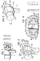
- the head of the mallet basically, has an internal or core element 100 - see Fig. 7, and a second, monolithic outer cover body 200 - see Fig. 2.
- the outer cover body 200 essentially entirely surrounds the inner core 100.
- the central core or head 100 is made of heavy-weight metal, such as cast steel. It has a central portion 101 (Fig. 7) which terminates in two end or front planes 102, 103 extending vertically with respect to planes 101, that is, parallel to the direction of the handle L.
- the front and back planes 103 have protrusions 104, 105 (Fig. 7) extending therefrom. These protrusions increase the mass of the core and compensate for loss of equivalent mass in the region of the opening for the handle. They are positioned in line with the handle hole.
- the protrusions 104, 105 have rounded end portions in order to prevent force concentrations at corners from arising in use of the tool.
- the core body 100 has an upper face 106 which is, basical ly, plane and horizontal - that is, extending at right angles to the end walls 102, 103 - and which merges with lateral walls 107, 108 which extend essentially in vertical direction.
- the walls 107, 108 need not, however, be essentially vertical; they can taper somewhat inwardly, that is, towards a center plane of symmetry passing vertically through the core.
- the junction lines of plane 106 and the lateral planes 107, 108 are curved surfaces, as best seen in Fig. 7.
- the central core structure does not have a generally cylindrical or prismatic outline; rather, it is ellipsoid-shaped, with plane end and top, bottom and side surfaces.
- the curved surfaces 110, 111 and 112 are clearly seen in Fig. 7.
- the surfaces 112 may be straight, as seen in Fig-. 7, or somewhat curved or rounded.
- the surfaces 110, 111 also, can be straight or rounded, the reference to the ellipsoid shape being intended to refer to the general appearance aspect, rather than to mathematically defined surfaces.
- Surfaces 112 may extend to the bottom surface 109.
- the polymeric body 200 which includes the actual striking surfaces with which the tool is to be used, is a single integral monolithic element. It covers and surrounds the core 100, and has two outer end portions 201, 202 (Figs. 2, 4). Basically, the extreme end portions of the outer ends 201, 202 are essentially cylindrical at their outer circumference; they may, however, also be prismatic. The diameter of the outer portions progressively increase, so that they can be termed frusto-conical; from a narrower free end, the diameter of the outer end portion increases towards the center region of the mallet, and increases in the region at least approximately even with the planes 102, 103, or in advance thereof - see Fig. 5. The increase in diameter of the end portions 201, 202 can be gradual or, as shown in figs. 2, 5, may include a step 203.
- the outer plastic body 200 has lateral planes 204 (Fig. 5) and an upper surface 205.
- the exact shape and configuration of planes 204 and surface 205 is not critical or important; it will be governed largely by the internal shape of the core, and can be arranged to have a suitable configuration which provides for a pleasing appearance. It is of fundamental importance, however, that the thickness of the walls defined by the surfaces 204 and 205 is approximately constant, that is, that the covering thickness of plastic material internally of the walls or surfaces 204, 205 over the steel core 100 is generally and approximately uniform.
- the ends 201, 202 have a generally acceptable and suitable diameter, for example about 5.5 cm - roughly slightly larger than 2 inches.
- the corresponding portion 102 of the body 100 is substantially smaller, for example, has a diameter of about 2.5 cm - about 1 inch.
- the inclined planes 110, 111, 112, which are contiguous to the vertical wall 102, provide for gradual decrease of the wall thickness of the adjacent covering walls of the elastomer body 100 without any transition formed by sharp edges which might result in force concentration. At the same time, one can readily observe - see Figs.
- Fig. 4 includes the force diagram in which the internal forces B' can be seen to be substantially smaller than the reaction forces A' which represent the action of the tool on the object being struck.
- the cross-sectional area of the body 200 increases from the terminal end of the surfaces 201, 202 towards the center until it becomes between 30% to 50% larger than the frontal area of the respective surface 201, 202.
- the frontal area 201, 202 of course is that area which is available for hammering, that is, where the blow is being struck.
- the internal resisting force of the plastic material which is resilient and elastic, is notably less than the force which it is capable of absorb ing in compression when the core 100 acts on the surface to be struck through the elastic covering.
- the presence of the plurality of inclined planes which start from the end faces 102, 103 of the core 100 distributes the forces within the plastic end portions uniformly and without force concentrations which might result in breakage or fissures of or in the material.
- the outer cover being monolithic, totally encloses the core 100.
- a portion of the reaction force can be absorbed by the remainder of the plastic part 200; some of the plastic, at the side remote from the object to be struck will be placed in tension. This further reduces the forces within the monolithic body 200 to a value which is smaller than that which can be theoretical ly calculated. It has been found that an average force distribution within the plastic material which is 40% smaller than that at the end which strikes the object will have to be absorbed by the material 200 in the regions which are not in direct line with the blow.
- the overall force distribution within the plastic body 200 thus will be comparatively uniform and much more so than in prior art structures.
- the balance of the head is excellent, since the weight distribution will be such that the center of gravity of the overall structure is essentially similar to that of a common hammer without a plastic or other non-marring end portion, a result not obtained with hammers illustrated, for example, in Fig. 1.
- the protrusions 104, 105 which can be so positioned that they, essentially, balance the loss of material within the core due to the presence of the handle hole, provide for excellent balance.
- the handle can be attached into the combination of the core 100 in a conventional manner.
- Fig. 6 illustrates an arrangement in which an orifice or a cavity M is formed, which is free from plastic material of the body 200.
- the handle can be wedged therein, or fitted, using bonding adhesives and, if desired, an expansion wedge which can be passed through the closed end of the orifice M (not shown) in conventional manner can be used.
- FIG. 4 Another alternative, and which is a preferred form, is attaching the handle as shown in Figs. 4 and 5.
- This arrangement provides for a sleeve or lining 206 extending into the throughopening M' and forming part of the outer plastic covering body 200.
- the sleeve or lining (206) is fitted into an enlargement 113 formed in the body 100, and made of the same material and integral with the elastomer body 200.
- the internally fitting sleeve or lining 206 provides for the effect of a bushing or a soft pillow seat, while, on the other, providing for continuity of absorption of forces to the elastomer body 200, by securing the body 200 within the head 200 and directly to the handle L.
- the lower face 109 of the body 100 need not and usually is not covered by the material of the body 200. Body 200, thus, will not penetrate inside the cavity M or M', respectively, for the handle L.
- the body 200 is preferably bonded or adhered to the body 100 by suitable adhesives or bonding materials, compatible with the respective materials of the body 200 and 100.
- the lateral faces of the core body 100 and the outer cover 200 can be formed with matching, interfitting grooves, channels, or orifices.
- a groove 114 (Fig. 7) is provided in the lateral face 108 of the core, into which a matching ridge formed on the body 200 (not shown) fits - see, also, the phantom view of Fig. 3.
- the specific shapes which the body 100 or the body 200 may have can be varied, as required.
- the dimensions given are approximate and not critical, and can be changed to suit various requirements of use.
- a cylindrical outer surface 201, 202 is preferred, although the outer surface may, also, be polygonal.
- the materials used are conventional and. can be those customarily used in connection with prior art mallets for similar use.
Abstract
Description
- The present invention relates to hammers or mallets, and more particularly to mallets with an elastic head for use in sheet metal or automotive bodyshops.
- Various types of mallets or hammers with elastic heads are used in workshops, particularly for sheet metal shaping and forming, for repairs, in automotive body and fender shops, and the like. Usually, the head of the mallet is made of rubber or similar elastomer material, or of plastic of more or less hardness. Blows can be struck against a work surface which may be painted, without marring the surface.
- It is difficult to provide for good retention of an elastic or plastic head on a hammer body, particularly if the body of the hammer is to have a substantial weight so that the blows to be struck will provide sufficient impact force on the object or surface which is being hammered. Mallets, therefore, should have a core of heavy material, such as iron, steel, or the like, which is encased by rubber, plastic, or other similar substance, which is non-marring with respect to the surface to be struck. The surface to be struck should have the force of the hammer applied thereto evenly; this requires essentially even or uniform force transfer between the striking surface of the mallet and the interior components thereof. In the past, it was difficult to provide for good force transfer which insures adhesion of the outer elastic or non-marring rubber or plastic or similar portion without degradation or breakage thereof.
- The invention as claimed is intended to provide a hammer or mallet which has a central head of an essentially non-yielding material, such as iron or steel, and an outer cover or coating of a strong flexible material such as a plastic polymer, rubberized elastomer, or the like, which is preferably non-marring when striking a surface, and in which forces being transferred upon striking a surface can be absorbed internally without causing stress concentrations leading to failure or rupture of the plastic or elastomer cover surrounding the iron core.
- Briefly, the core element is made of a metallic body, steel or iron for example, which has an opening therein to which a hammer handle can be attached. The metal core has an upper face and lateral faces, as well as end faces. The end faces are vertical and have projecting therefrom rounded-off protrusions fitting into similarly shaped openings in the plastic cover ends. The planes of the other surfaces are relatively mutually positioned to be oblique, that is, at other than right angles, and of diverging configuration. The transverse central section of the metallic head is larger and wider than the ends, and the extreme vertical faces having an area which is between 50% to 70% of the area of a plane passing transversely through the center of the core. Consequently, the portion of the projected oblique or inclined surfaces of the core are between 50% to 30% of the total transverse area. Preferably, the plastic ends of the hammer are of essentially cylindrical cross section.
- In the drawings:
- Fig. 1 illustrates a hammer in accordance with the prior art in part-longitudinal sectional view;
- Fig. 2 is a perspective view of a hammer incorporating the present invention;
- Fig. 3 is a phantom perspective view of Fig. 2, showing the internal construction;
- Fig. 4 is a vertical section along the plane y-y' of Fig. 2;
- Fig. 5 is a horizontal, partly offset section along the section line x-x' of Fig. 4, in which the right-hand plane of the section is below that of the left-hand section plane - with respect to Fig. 4;
- Fig. 6 is a view similar to Fig. 4 and illustrating another embodiment; and
- Fig. 7 is a perspective view of the core element also seen in Fig. 3, to an enlarged scale, and omitting the handle.
- A typical type of mallet or hammer of the general configuration to which the present invention relates, and constructed according to the prior art, is shown in Fig. 1. This tool is a mallet, particularly suitable in automotive body-and-fender work. A handle L is fitted into a cavity M of a core N. The core N has end portions 0 which have terminal striker parts P of elastic material attached thereto. The striker ends P, typically of a plastic polymer material, are fitted to the core N in a suitable manner, for example by a press fit on a central projection Q, projecting from the core N into a recess or seat R formed in the plastic material; or by screw attachment passing in or through the plastic end parts P and into the core. Both attachment arrangements - screw attachment as well as press fit - can be used. The seat formed by the projection Q in the recess R of the end portion P results in damage to the end portion P. In use, the end portion P should transfer force from the center core N uniformly distributed throughout its end area or surface, as shown by the force arrows B. A reaction force must be absorbed by the end portion P, see the force arrows A. The forces illustrated by arrows A and B are equal and in opposite direction, under ideal conditions. Unfortunately, the ideal conditions do not pertain since the fitting surfaces terminate in corners S and T and force concentrations will occur at these corners. The force concentrations and non-uniformity of force distribution, consequent to the fit of the projection Q in the recess R results in loosening of the retentive force of the end portion P on the core N and, in limiting cases, in fracture of the end element or end portion P.
- It has also already been proposed to construct the head N of two half-shells. This construction is not shown; in general, the internal arrangement is somewhat similar to that illustrated in Fig. 1. The half-shells are arranged to clamp projecting end portions from the elastic ends therebetween. The half-shells are held together by a stud, bolt or the like. This arrangement has the advantage that the elastic heads or end portions P can be easily changed if they should become damaged or break.
- This arrangement is suitable particularly when the lifetime of the end portion is not expected to be extensive, since rapid interchange is simple. The balance of the overall head of the mallet is frequently not as desired by the mechanic or user of the tool, and obtaining appropriate weight, as well as suitable weight distribution is difficult. The force distribution upon striking a blow with a hammer or mallet of this type is non-uniform and thus this tool has an average lifetime, before replacement of the ends, which is substantially less than that of other tools used in an automotive repair shop, which is undesirable for many applications.
- The mallet head in accordance with the present invention has a specific shape and arrangement of the internal surfaces of the core to which matching surfaces of elastomer or other plastic ends are applied, the surface configurations being especially selected to provide for uniformity of force transfer without concentration of forces at points which might cause damage to the head structure and, in a limiting case, loosening and breakage thereof.
- Referring to Fig. 2: The handle L can be in accordance with any well known hammer or mallet handle, and can be similar to that used in connection with any mallet of the prior art. Since the particular type of handle does not form a part of the present invention, it is shown in broken lines in the drawings.
- The head of the mallet, basically, has an internal or core element 100 - see Fig. 7, and a second, monolithic outer cover body 200 - see Fig. 2. The
outer cover body 200 essentially entirely surrounds theinner core 100. - The central core or
head 100 is made of heavy-weight metal, such as cast steel. It has a central portion 101 (Fig. 7) which terminates in two end orfront planes planes 101, that is, parallel to the direction of the handle L. The front andback planes 103 haveprotrusions 104, 105 (Fig. 7) extending therefrom. These protrusions increase the mass of the core and compensate for loss of equivalent mass in the region of the opening for the handle. They are positioned in line with the handle hole. Theprotrusions - The
core body 100 has anupper face 106 which is, basical ly, plane and horizontal - that is, extending at right angles to theend walls 102, 103 - and which merges withlateral walls walls plane 106 and thelateral planes curved surfaces surfaces 112 may be straight, as seen in Fig-. 7, or somewhat curved or rounded. Thesurfaces Surfaces 112 may extend to thebottom surface 109. - ' The
polymeric body 200, which includes the actual striking surfaces with which the tool is to be used, is a single integral monolithic element. It covers and surrounds thecore 100, and has twoouter end portions 201, 202 (Figs. 2, 4). Basically, the extreme end portions of theouter ends planes end portions step 203. - The outer
plastic body 200 has lateral planes 204 (Fig. 5) and anupper surface 205. The exact shape and configuration ofplanes 204 andsurface 205 is not critical or important; it will be governed largely by the internal shape of the core, and can be arranged to have a suitable configuration which provides for a pleasing appearance. It is of fundamental importance, however, that the thickness of the walls defined by thesurfaces steel core 100 is generally and approximately uniform. - Uniformity of thickness of the covering walls has this effect in force transfer relationships: The ends 201, 202 (see Figs. 4 and 5) have a generally acceptable and suitable diameter, for example about 5.5 cm - roughly slightly larger than 2 inches. The corresponding
portion 102 of thebody 100 is substantially smaller, for example, has a diameter of about 2.5 cm - about 1 inch. Theinclined planes vertical wall 102, provide for gradual decrease of the wall thickness of the adjacent covering walls of theelastomer body 100 without any transition formed by sharp edges which might result in force concentration. At the same time, one can readily observe - see Figs. 4 and 5 - that the transverse area of thebody 100 is at all times at least 30% to 50% larger than the frontal area of thesurface - The cross-sectional area of the
body 200 increases from the terminal end of thesurfaces respective surface frontal area core 100 distributes the forces within the plastic end portions uniformly and without force concentrations which might result in breakage or fissures of or in the material. - The outer cover, being monolithic, totally encloses the
core 100. Thus, a portion of the reaction force can be absorbed by the remainder of theplastic part 200; some of the plastic, at the side remote from the object to be struck will be placed in tension. This further reduces the forces within themonolithic body 200 to a value which is smaller than that which can be theoretical ly calculated. It has been found that an average force distribution within the plastic material which is 40% smaller than that at the end which strikes the object will have to be absorbed by thematerial 200 in the regions which are not in direct line with the blow. - The overall force distribution within the
plastic body 200 thus will be comparatively uniform and much more so than in prior art structures. The balance of the head is excellent, since the weight distribution will be such that the center of gravity of the overall structure is essentially similar to that of a common hammer without a plastic or other non-marring end portion, a result not obtained with hammers illustrated, for example, in Fig. 1. Theprotrusions - The handle can be attached into the combination of the core 100 in a conventional manner. Fig. 6 illustrates an arrangement in which an orifice or a cavity M is formed, which is free from plastic material of the
body 200. The handle can be wedged therein, or fitted, using bonding adhesives and, if desired, an expansion wedge which can be passed through the closed end of the orifice M (not shown) in conventional manner can be used. - Another alternative, and which is a preferred form, is attaching the handle as shown in Figs. 4 and 5. This arrangement provides for a sleeve or lining 206 extending into the throughopening M' and forming part of the outer
plastic covering body 200. The sleeve or lining (206) is fitted into anenlargement 113 formed in thebody 100, and made of the same material and integral with theelastomer body 200. On the one hand, the internally fitting sleeve or lining 206 provides for the effect of a bushing or a soft pillow seat, while, on the other, providing for continuity of absorption of forces to theelastomer body 200, by securing thebody 200 within thehead 200 and directly to the handle L. - The
lower face 109 of thebody 100 need not and usually is not covered by the material of thebody 200.Body 200, thus, will not penetrate inside the cavity M or M', respectively, for the handle L. - The
body 200 is preferably bonded or adhered to thebody 100 by suitable adhesives or bonding materials, compatible with the respective materials of thebody core body 100 and theouter cover 200 can be formed with matching, interfitting grooves, channels, or orifices. As an illustration, a groove 114 (Fig. 7) is provided in thelateral face 108 of the core, into which a matching ridge formed on the body 200 (not shown) fits - see, also, the phantom view of Fig. 3. - Various changes and modifications may be made, and the specific shapes which the
body 100 or thebody 200 may have can be varied, as required. The dimensions given are approximate and not critical, and can be changed to suit various requirements of use. Generally, a cylindricalouter surface
Claims (10)
characterised in that
and said unitary plastic cover element (200) extends over said core to a region short of the edge of said opening.
and said unitary plastic cover element (200) is formed with a depending unitary sleeve (206) extending into said through-bore to provide a cushion and connecting portion for the handle (L), the handle extending through said opening and into said sleeve (206).
Priority Applications (1)
| Application Number | Priority Date | Filing Date | Title |
|---|---|---|---|
| AT81102662T ATE6602T1 (en) | 1980-04-16 | 1981-04-08 | HAND HAMMER WITH FLEXIBLE HEAD. |
Applications Claiming Priority (2)
| Application Number | Priority Date | Filing Date | Title |
|---|---|---|---|
| AR280707 | 1980-04-16 | ||
| AR280707A AR218840A1 (en) | 1980-04-16 | 1980-04-16 | IMPROVEMENTS IN HAMMERS WITH ELASTIC HAMMER |
Publications (2)
| Publication Number | Publication Date |
|---|---|
| EP0038021A1 true EP0038021A1 (en) | 1981-10-21 |
| EP0038021B1 EP0038021B1 (en) | 1984-03-14 |
Family
ID=3474875
Family Applications (1)
| Application Number | Title | Priority Date | Filing Date |
|---|---|---|---|
| EP81102662A Expired EP0038021B1 (en) | 1980-04-16 | 1981-04-08 | Mallet with flexible head |
Country Status (8)
| Country | Link |
|---|---|
| US (1) | US4373565A (en) |
| EP (1) | EP0038021B1 (en) |
| JP (1) | JPS56152590A (en) |
| AR (1) | AR218840A1 (en) |
| AT (1) | ATE6602T1 (en) |
| BR (1) | BR8102319A (en) |
| DE (1) | DE3162589D1 (en) |
| ES (1) | ES265982Y (en) |
Families Citing this family (14)
| Publication number | Priority date | Publication date | Assignee | Title |
|---|---|---|---|---|
| US6128977A (en) * | 1997-04-09 | 2000-10-10 | Emerson Electric Co. | Shock-absorbing claw hammer |
| US6763747B1 (en) | 1997-04-09 | 2004-07-20 | Emerson Electric Co. | Shock absorbing hammer and handle assembly |
| US6016722A (en) * | 1997-07-21 | 2000-01-25 | Emerson Electric Co. | Shock-absorbing claw hammer |
| AU8850598A (en) * | 1997-08-29 | 1999-03-22 | Judith Gertrude Bartlett | Riveting tool and method to reduce marring of the workpiece |
| US6477922B1 (en) | 1998-04-29 | 2002-11-12 | John A. Burnett | Impact tool |
| US6106482A (en) * | 1999-05-20 | 2000-08-22 | Health & Technology, Inc. | Reflex hammer |
| US20080189930A1 (en) * | 2007-02-13 | 2008-08-14 | Yung-Shou Chen | Method for making a hammer |
| CA2594152A1 (en) * | 2007-08-01 | 2009-02-01 | Gordon C. Cobb | Mallethead pro 3 |
| US9242360B2 (en) | 2012-04-18 | 2016-01-26 | Apex Brands, Inc. | Multiple purpose hand tool |
| US9789597B2 (en) | 2014-03-07 | 2017-10-17 | Estwing Manufacturing Company, Inc. | Striking tool with attached striking surface |
| US9802304B2 (en) | 2014-03-07 | 2017-10-31 | Estwing Manufacturing Company, Inc. | Aluminum striking tools |
| CN105033955A (en) * | 2015-07-14 | 2015-11-11 | 浙江柏尔木业有限公司 | Furniture installation hammer |
| TWI564123B (en) * | 2016-08-03 | 2017-01-01 | 鴻安國際興業有限公司 | Plastic bottle |
| USD829074S1 (en) | 2016-09-21 | 2018-09-25 | Estwing Manufacturing Company, Inc. | Hammer |
Citations (1)
| Publication number | Priority date | Publication date | Assignee | Title |
|---|---|---|---|---|
| AU1130766A (en) * | 1967-09-04 | 1969-03-13 | Barry Brown John | Improvements in or relating to anti-recoil hand tool |
Family Cites Families (8)
| Publication number | Priority date | Publication date | Assignee | Title |
|---|---|---|---|---|
| US52696A (en) * | 1866-02-20 | Improved elastic mallet | ||
| US1409449A (en) * | 1922-03-14 | Hammer | ||
| FR595706A (en) * | 1924-06-28 | 1925-10-08 | Vulcanized rubber mallets and mallets | |
| GB592900A (en) * | 1944-10-18 | 1947-10-02 | Walter Kurt Jahn | Hammer head and method of making same |
| US2570691A (en) * | 1946-01-31 | 1951-10-09 | Erick N Kindland | Hammer having replaceable striking heads |
| GB996383A (en) * | 1960-10-03 | 1965-06-30 | George Edward Marshall | Improvements relating to hammers |
| DE1277769B (en) * | 1965-08-12 | 1968-09-12 | Max Baumann U Co Fa | Kickback free hand hammer |
| US3844321A (en) * | 1971-06-22 | 1974-10-29 | Custom Electronic Syst Inc | Unitarily cast hammer |
-
1980
- 1980-04-16 AR AR280707A patent/AR218840A1/en active
-
1981
- 1981-03-17 US US06/244,782 patent/US4373565A/en not_active Expired - Fee Related
- 1981-04-08 AT AT81102662T patent/ATE6602T1/en not_active IP Right Cessation
- 1981-04-08 EP EP81102662A patent/EP0038021B1/en not_active Expired
- 1981-04-08 DE DE8181102662T patent/DE3162589D1/en not_active Expired
- 1981-04-13 BR BR8102319A patent/BR8102319A/en unknown
- 1981-04-14 JP JP5513681A patent/JPS56152590A/en active Pending
- 1981-04-14 ES ES1981265982U patent/ES265982Y/en not_active Expired
Patent Citations (1)
| Publication number | Priority date | Publication date | Assignee | Title |
|---|---|---|---|---|
| AU1130766A (en) * | 1967-09-04 | 1969-03-13 | Barry Brown John | Improvements in or relating to anti-recoil hand tool |
Also Published As
| Publication number | Publication date |
|---|---|
| ATE6602T1 (en) | 1984-03-15 |
| DE3162589D1 (en) | 1984-04-19 |
| ES265982U (en) | 1983-02-01 |
| ES265982Y (en) | 1983-07-16 |
| JPS56152590A (en) | 1981-11-26 |
| US4373565A (en) | 1983-02-15 |
| AR218840A1 (en) | 1980-06-30 |
| EP0038021B1 (en) | 1984-03-14 |
| BR8102319A (en) | 1981-12-08 |
Similar Documents
| Publication | Publication Date | Title |
|---|---|---|
| EP0038021B1 (en) | Mallet with flexible head | |
| US4610561A (en) | Sectional structure for carpentry, particularly to realize cubicles | |
| US6202511B1 (en) | Vibration damped hammer | |
| US2678853A (en) | Securing means for hammers | |
| US20090078090A1 (en) | Recoilles Hammer | |
| US4683784A (en) | Hammer | |
| WO2001049460A1 (en) | Composite tool and method of manufacture | |
| PL178643B1 (en) | Fixing device incorporating a nail and a tensioning member | |
| AU738137B2 (en) | Shock absorption system for a striking tool | |
| US3148716A (en) | Impact tool with chip-resistant striking face | |
| US2884969A (en) | Hammer construction with shock absorbing means | |
| US6463832B1 (en) | Capped head hammer | |
| US3208724A (en) | Carpenter's claw hammer with vibration dampening means | |
| US3341261A (en) | Portable impact tools | |
| US6457384B1 (en) | Capped head hammer | |
| AU746050B2 (en) | Nail magazine | |
| US4718313A (en) | Hammer head for a hammer | |
| US5213023A (en) | Hammer | |
| US3129737A (en) | Hammer with detachable head | |
| US2337440A (en) | Flexible handle for tools | |
| US3779296A (en) | Handle for manual percussion tools | |
| US3394745A (en) | Hammer head mounting | |
| US20210323134A1 (en) | Hammer With Improved Striking Face | |
| US5152629A (en) | Tool handle wedge | |
| MXPA05003617A (en) | Manufacture of an offset head nail. |
Legal Events
| Date | Code | Title | Description |
|---|---|---|---|
| PUAI | Public reference made under article 153(3) epc to a published international application that has entered the european phase |
Free format text: ORIGINAL CODE: 0009012 |
|
| AK | Designated contracting states |
Designated state(s): AT BE CH DE FR GB IT LU NL SE |
|
| 17P | Request for examination filed |
Effective date: 19820417 |
|
| ITF | It: translation for a ep patent filed |
Owner name: JACOBACCI & PERANI S.P.A. |
|
| GRAA | (expected) grant |
Free format text: ORIGINAL CODE: 0009210 |
|
| AK | Designated contracting states |
Designated state(s): AT BE CH DE FR GB IT LI LU NL SE |
|
| PG25 | Lapsed in a contracting state [announced via postgrant information from national office to epo] |
Ref country code: SE Free format text: THE PATENT HAS BEEN ANNULLED BY A DECISION OF A NATIONAL AUTHORITY Effective date: 19840314 Ref country code: NL Effective date: 19840314 Ref country code: LI Effective date: 19840314 Ref country code: CH Effective date: 19840314 Ref country code: BE Effective date: 19840314 Ref country code: AT Effective date: 19840314 |
|
| REF | Corresponds to: |
Ref document number: 6602 Country of ref document: AT Date of ref document: 19840315 Kind code of ref document: T |
|
| PGFP | Annual fee paid to national office [announced via postgrant information from national office to epo] |
Ref country code: DE Payment date: 19840319 Year of fee payment: 4 |
|
| REF | Corresponds to: |
Ref document number: 3162589 Country of ref document: DE Date of ref document: 19840419 |
|
| PG25 | Lapsed in a contracting state [announced via postgrant information from national office to epo] |
Ref country code: LU Free format text: LAPSE BECAUSE OF NON-PAYMENT OF DUE FEES Effective date: 19840430 |
|
| ET | Fr: translation filed | ||
| PGFP | Annual fee paid to national office [announced via postgrant information from national office to epo] |
Ref country code: FR Payment date: 19840517 Year of fee payment: 4 |
|
| REG | Reference to a national code |
Ref country code: CH Ref legal event code: PL |
|
| NLV1 | Nl: lapsed or annulled due to failure to fulfill the requirements of art. 29p and 29m of the patents act | ||
| PLBE | No opposition filed within time limit |
Free format text: ORIGINAL CODE: 0009261 |
|
| STAA | Information on the status of an ep patent application or granted ep patent |
Free format text: STATUS: NO OPPOSITION FILED WITHIN TIME LIMIT |
|
| 26N | No opposition filed | ||
| PG25 | Lapsed in a contracting state [announced via postgrant information from national office to epo] |
Ref country code: FR Free format text: LAPSE BECAUSE OF NON-PAYMENT OF DUE FEES Effective date: 19871230 |
|
| GBPC | Gb: european patent ceased through non-payment of renewal fee | ||
| PG25 | Lapsed in a contracting state [announced via postgrant information from national office to epo] |
Ref country code: DE Effective date: 19880101 |
|
| REG | Reference to a national code |
Ref country code: FR Ref legal event code: ST |
|
| PG25 | Lapsed in a contracting state [announced via postgrant information from national office to epo] |
Ref country code: GB Effective date: 19881118 |