EP0037874A1 - Diverter valve - Google Patents
Diverter valve Download PDFInfo
- Publication number
- EP0037874A1 EP0037874A1 EP81100764A EP81100764A EP0037874A1 EP 0037874 A1 EP0037874 A1 EP 0037874A1 EP 81100764 A EP81100764 A EP 81100764A EP 81100764 A EP81100764 A EP 81100764A EP 0037874 A1 EP0037874 A1 EP 0037874A1
- Authority
- EP
- European Patent Office
- Prior art keywords
- slide plate
- diverter valve
- sealing
- fluid
- metal
- Prior art date
- Legal status (The legal status is an assumption and is not a legal conclusion. Google has not performed a legal analysis and makes no representation as to the accuracy of the status listed.)
- Withdrawn
Links
- 238000007789 sealing Methods 0.000 claims abstract description 33
- 239000012530 fluid Substances 0.000 claims abstract description 29
- 239000002184 metal Substances 0.000 claims description 16
- 229910052751 metal Inorganic materials 0.000 claims description 16
- 238000000034 method Methods 0.000 claims description 15
- 230000013011 mating Effects 0.000 claims description 7
- 238000005121 nitriding Methods 0.000 claims description 7
- 229910001315 Tool steel Inorganic materials 0.000 claims description 4
- 238000004519 manufacturing process Methods 0.000 claims description 3
- 239000000463 material Substances 0.000 description 36
- 230000000694 effects Effects 0.000 description 6
- 229910000906 Bronze Inorganic materials 0.000 description 5
- 125000006850 spacer group Chemical group 0.000 description 5
- VYZAMTAEIAYCRO-UHFFFAOYSA-N Chromium Chemical compound [Cr] VYZAMTAEIAYCRO-UHFFFAOYSA-N 0.000 description 3
- 239000004033 plastic Substances 0.000 description 3
- 229920003023 plastic Polymers 0.000 description 3
- VEXZGXHMUGYJMC-UHFFFAOYSA-N Hydrochloric acid Chemical compound Cl VEXZGXHMUGYJMC-UHFFFAOYSA-N 0.000 description 2
- -1 blow molding Substances 0.000 description 2
- 238000000576 coating method Methods 0.000 description 2
- 230000007547 defect Effects 0.000 description 2
- 238000001125 extrusion Methods 0.000 description 2
- 238000001914 filtration Methods 0.000 description 2
- 239000000178 monomer Substances 0.000 description 2
- 239000002985 plastic film Substances 0.000 description 2
- 229920000642 polymer Polymers 0.000 description 2
- 238000005496 tempering Methods 0.000 description 2
- 239000011345 viscous material Substances 0.000 description 2
- OKTJSMMVPCPJKN-UHFFFAOYSA-N Carbon Chemical compound [C] OKTJSMMVPCPJKN-UHFFFAOYSA-N 0.000 description 1
- VEXZGXHMUGYJMC-UHFFFAOYSA-M Chloride anion Chemical compound [Cl-] VEXZGXHMUGYJMC-UHFFFAOYSA-M 0.000 description 1
- 239000004677 Nylon Substances 0.000 description 1
- 239000004698 Polyethylene Substances 0.000 description 1
- XAGFODPZIPBFFR-UHFFFAOYSA-N aluminium Chemical compound [Al] XAGFODPZIPBFFR-UHFFFAOYSA-N 0.000 description 1
- 230000015572 biosynthetic process Effects 0.000 description 1
- 238000000071 blow moulding Methods 0.000 description 1
- 239000010974 bronze Substances 0.000 description 1
- 229910052799 carbon Inorganic materials 0.000 description 1
- 238000005255 carburizing Methods 0.000 description 1
- 230000015556 catabolic process Effects 0.000 description 1
- 239000011248 coating agent Substances 0.000 description 1
- 238000010276 construction Methods 0.000 description 1
- 239000000356 contaminant Substances 0.000 description 1
- 230000003247 decreasing effect Effects 0.000 description 1
- 238000006731 degradation reaction Methods 0.000 description 1
- 230000002939 deleterious effect Effects 0.000 description 1
- 238000010586 diagram Methods 0.000 description 1
- 230000008030 elimination Effects 0.000 description 1
- 238000003379 elimination reaction Methods 0.000 description 1
- 239000000835 fiber Substances 0.000 description 1
- 239000000499 gel Substances 0.000 description 1
- 239000012943 hotmelt Substances 0.000 description 1
- 239000012535 impurity Substances 0.000 description 1
- 238000002347 injection Methods 0.000 description 1
- 239000007924 injection Substances 0.000 description 1
- 150000002739 metals Chemical class 0.000 description 1
- 229920001778 nylon Polymers 0.000 description 1
- 230000035515 penetration Effects 0.000 description 1
- 229920000728 polyester Polymers 0.000 description 1
- 229920000573 polyethylene Polymers 0.000 description 1
- 230000001681 protective effect Effects 0.000 description 1
- 238000005507 spraying Methods 0.000 description 1
- 239000007858 starting material Substances 0.000 description 1
- 230000001360 synchronised effect Effects 0.000 description 1
- 229920002994 synthetic fiber Polymers 0.000 description 1
- 239000004758 synthetic textile Substances 0.000 description 1
Images

Classifications
-
- F—MECHANICAL ENGINEERING; LIGHTING; HEATING; WEAPONS; BLASTING
- F16—ENGINEERING ELEMENTS AND UNITS; GENERAL MEASURES FOR PRODUCING AND MAINTAINING EFFECTIVE FUNCTIONING OF MACHINES OR INSTALLATIONS; THERMAL INSULATION IN GENERAL
- F16K—VALVES; TAPS; COCKS; ACTUATING-FLOATS; DEVICES FOR VENTING OR AERATING
- F16K11/00—Multiple-way valves, e.g. mixing valves; Pipe fittings incorporating such valves
- F16K11/02—Multiple-way valves, e.g. mixing valves; Pipe fittings incorporating such valves with all movable sealing faces moving as one unit
- F16K11/06—Multiple-way valves, e.g. mixing valves; Pipe fittings incorporating such valves with all movable sealing faces moving as one unit comprising only sliding valves, i.e. sliding closure elements
-
- B—PERFORMING OPERATIONS; TRANSPORTING
- B01—PHYSICAL OR CHEMICAL PROCESSES OR APPARATUS IN GENERAL
- B01D—SEPARATION
- B01D35/00—Filtering devices having features not specifically covered by groups B01D24/00 - B01D33/00, or for applications not specifically covered by groups B01D24/00 - B01D33/00; Auxiliary devices for filtration; Filter housing constructions
- B01D35/12—Devices for taking out of action one or more units of multi- unit filters, e.g. for regeneration
-
- B—PERFORMING OPERATIONS; TRANSPORTING
- B29—WORKING OF PLASTICS; WORKING OF SUBSTANCES IN A PLASTIC STATE IN GENERAL
- B29C—SHAPING OR JOINING OF PLASTICS; SHAPING OF MATERIAL IN A PLASTIC STATE, NOT OTHERWISE PROVIDED FOR; AFTER-TREATMENT OF THE SHAPED PRODUCTS, e.g. REPAIRING
- B29C48/00—Extrusion moulding, i.e. expressing the moulding material through a die or nozzle which imparts the desired form; Apparatus therefor
- B29C48/25—Component parts, details or accessories; Auxiliary operations
- B29C48/254—Sealing means
- B29C48/2545—Sealing means for filters
-
- B—PERFORMING OPERATIONS; TRANSPORTING
- B29—WORKING OF PLASTICS; WORKING OF SUBSTANCES IN A PLASTIC STATE IN GENERAL
- B29C—SHAPING OR JOINING OF PLASTICS; SHAPING OF MATERIAL IN A PLASTIC STATE, NOT OTHERWISE PROVIDED FOR; AFTER-TREATMENT OF THE SHAPED PRODUCTS, e.g. REPAIRING
- B29C48/00—Extrusion moulding, i.e. expressing the moulding material through a die or nozzle which imparts the desired form; Apparatus therefor
- B29C48/25—Component parts, details or accessories; Auxiliary operations
- B29C48/255—Flow control means, e.g. valves
- B29C48/2554—Flow control means, e.g. valves provided in or in the proximity of filter devices
-
- B—PERFORMING OPERATIONS; TRANSPORTING
- B29—WORKING OF PLASTICS; WORKING OF SUBSTANCES IN A PLASTIC STATE IN GENERAL
- B29C—SHAPING OR JOINING OF PLASTICS; SHAPING OF MATERIAL IN A PLASTIC STATE, NOT OTHERWISE PROVIDED FOR; AFTER-TREATMENT OF THE SHAPED PRODUCTS, e.g. REPAIRING
- B29C48/00—Extrusion moulding, i.e. expressing the moulding material through a die or nozzle which imparts the desired form; Apparatus therefor
- B29C48/25—Component parts, details or accessories; Auxiliary operations
- B29C48/36—Means for plasticising or homogenising the moulding material or forcing it through the nozzle or die
- B29C48/50—Details of extruders
- B29C48/69—Filters or screens for the moulding material
- B29C48/691—Arrangements for replacing filters, e.g. with two parallel filters for alternate use
-
- F—MECHANICAL ENGINEERING; LIGHTING; HEATING; WEAPONS; BLASTING
- F16—ENGINEERING ELEMENTS AND UNITS; GENERAL MEASURES FOR PRODUCING AND MAINTAINING EFFECTIVE FUNCTIONING OF MACHINES OR INSTALLATIONS; THERMAL INSULATION IN GENERAL
- F16K—VALVES; TAPS; COCKS; ACTUATING-FLOATS; DEVICES FOR VENTING OR AERATING
- F16K11/00—Multiple-way valves, e.g. mixing valves; Pipe fittings incorporating such valves
- F16K11/02—Multiple-way valves, e.g. mixing valves; Pipe fittings incorporating such valves with all movable sealing faces moving as one unit
-
- F—MECHANICAL ENGINEERING; LIGHTING; HEATING; WEAPONS; BLASTING
- F16—ENGINEERING ELEMENTS AND UNITS; GENERAL MEASURES FOR PRODUCING AND MAINTAINING EFFECTIVE FUNCTIONING OF MACHINES OR INSTALLATIONS; THERMAL INSULATION IN GENERAL
- F16K—VALVES; TAPS; COCKS; ACTUATING-FLOATS; DEVICES FOR VENTING OR AERATING
- F16K27/00—Construction of housing; Use of materials therefor
- F16K27/04—Construction of housing; Use of materials therefor of sliding valves
- F16K27/044—Construction of housing; Use of materials therefor of sliding valves slide valves with flat obturating members
-
- B—PERFORMING OPERATIONS; TRANSPORTING
- B29—WORKING OF PLASTICS; WORKING OF SUBSTANCES IN A PLASTIC STATE IN GENERAL
- B29C—SHAPING OR JOINING OF PLASTICS; SHAPING OF MATERIAL IN A PLASTIC STATE, NOT OTHERWISE PROVIDED FOR; AFTER-TREATMENT OF THE SHAPED PRODUCTS, e.g. REPAIRING
- B29C48/00—Extrusion moulding, i.e. expressing the moulding material through a die or nozzle which imparts the desired form; Apparatus therefor
- B29C48/03—Extrusion moulding, i.e. expressing the moulding material through a die or nozzle which imparts the desired form; Apparatus therefor characterised by the shape of the extruded material at extrusion
-
- Y—GENERAL TAGGING OF NEW TECHNOLOGICAL DEVELOPMENTS; GENERAL TAGGING OF CROSS-SECTIONAL TECHNOLOGIES SPANNING OVER SEVERAL SECTIONS OF THE IPC; TECHNICAL SUBJECTS COVERED BY FORMER USPC CROSS-REFERENCE ART COLLECTIONS [XRACs] AND DIGESTS
- Y10—TECHNICAL SUBJECTS COVERED BY FORMER USPC
- Y10T—TECHNICAL SUBJECTS COVERED BY FORMER US CLASSIFICATION
- Y10T137/00—Fluid handling
- Y10T137/8593—Systems
- Y10T137/86493—Multi-way valve unit
- Y10T137/86879—Reciprocating valve unit
Definitions
- This invention relates to a plastic filtration system for removing contaminants before product formation and more specifically to a diverter valve for directing the flow of viscous materials between alternate filters.
- process fluids such as "hot melts” and fluid monomer and polymer feed stocks, for example, nylon and polyesters
- process fluids such as "hot melts” and fluid monomer and polymer feed stocks, for example, nylon and polyesters
- process fluids such as "hot melts” and fluid monomer and polymer feed stocks, for example, nylon and polyesters
- Such processes typically embody extrusion, injection, blow molding, coating and spraying techniques, for example, in the manufacture of synthetic textile fibers, plastic tubing, plastic sheets and films and protective or insulating coatings for electrical wires.
- filter unit in the flow stream to effect removal of impurities which might result in an imperfect product or cause clogging of downstream equipment such as spinnerettes or extrusion dies.
- filters must be cleaned or replaced periodically.
- two parallel filter units (each of which may consist of more than one filter element) are provided together with changeover or diverter valves for alternatively diverting flow from one filter unit to the other so that one unit is in service while the other is being cleaned or replaced. It is usually desirable in such processes that filter changeover be accomplished without any significant reduction in process fluid flow or pressure to downstream equipment and without introducing air to the flow stream.
- a major problem in successfully developing a system of the type above-referred to is to provide diverter valves which will operate reliably at the pressures (approximately 5000 PSI) and at the high temperatures (approximately 600 degrees Fahrenheit or more) within the highly corrosive environment provided by the materials being processed.
- the prior art diverter valves have used a rotary plug valve or a variation thereof to control the flow of the material being processed.
- Such valves comprise a circular or conical plug which fits within a mating opening provided in the valve body with the plug containing flow ports requiring critical matching to obtain the desired flow.
- Such rotary plug valves when subjected to the pressures and temperatures required, have a tendency to freeze or seize up. If critical matching does not occur or a leak does occur, there is no possibility for the surface between the body and plug to be forced together to cure the defect.
- slide plates have been utilized in order to divert the flow of the material being processed.
- slide plates typically require non-metallic resilient seals to control or prevent leakage.
- Such seals again will not withstand high temperatures and pressures for long periods of time, thus providing a valve which is not reliable except for extremely short periods or in a different environment.
- Some examples of devices utilizing slide plates of various types within a plastic filtration system are shown by the following United States Patents: 2,661,497, 2,763,308, 2,786,504, 3,007,199, 3,059,276, 3,112,525, 3,145,746, and 3,503,096.
- a spool valve may be utilized to overcome some of the prior art problems. See United States Patent 3,833, 121. Although such a valve does overcome some of the problems, there is nonetheless a remaining problem evident in the spool valve, as well as in many of the prior art valves of the rotary, plug or slide plate types. That is, the construction in the flow areas through which the material being processed must move define isolated areas which are subject to stagnation. That is, the material being processed will move into these isolated areas and remain there. Depending upon the type of material involved, degradation will occur with extremely deleterious effects on the material being processed.
- the stagnant material will form hydrochloric acid and carbon and will then commence to increase in size (grow) until it extends into the flow of the material being processed and breaks off and contaminates the entire process. If other types of materials, such as polyethylene are being processed, the material will become cross-linked or carbonized in the stagnant area and will cause gels to form.
- a slide plate diverter valve for use with high viscosity fluids at temperatures in excess of about 400 degrees Fahrenheit and pressures in excess of about 1000 PSI, includes a metallic manifold block defining inlet and outlet ports with a metallic slide plate having a fluid flow passage-way in one surface thereof receiving the fluid flowing through the ports to provide a continuous flow path for the fluid with the flow path having no isolated regions subject to stagnation.
- a diverter valve constructed in accordance with more specific features of the present invention includes a manifold body defining inlet and outlet ports along with a slide plate having a cavity or recess defined therein and dimensioned to span the inlet flow port and one of the outlet flow ports simultaneously. By thus moving the slide plate between two limit positions provided for it, the material being processed may be caused to flow from the inlet port to either of the selected outlet ports and thus to the desired filter.
- a backing plate is provided to maintain the slide plate in contact with the manifold block at all times.
- a plurality of clamping or tie rods extend between the backing plate and the manifold block and are adjustable to apply a clamping pressure between the engaging surfaces of the manifold block and the slide plate to effect a seal therebetween. The only seal provided is the metal-to-metal seal existing between the mutually engaging surfaces of the slide plate and the manifold block.
- the surfaces which are mutually engaging and which provide the seal must be extremely hard, flat, and have a smooth finish.
- hot work tool steel has been utilized as the starting material.
- the material is carburized, utilizing the old and well-known carburizing process. Although such material when carburized does operate quite well, after subjection to the high temperatures (in excess of 400 degrees Fahrenheit) required in applications for which the diverter valve of the present invention are desired, it has been found that the carburized material begins to temper further and as a result thereof the valve galls and freezes up.
- the surfaces of the present valve which are mutually engaging to provide the seals are subjected to a nitriding process.
- the nitriding process which is preferred is the well-known Floe process and the hot work tool steel after being appropriately hardened and tempered is subjected to the nitriding process for a time sufficient to cause approximately a 10 mil penetration of the nitriding into the surface of the material although such is not critical. It has been found that through utilization of the nitriding process, the valve of the present invention even when subjected to high temperatures (600 to 700 degrees Fahrenheit) for extremely long periods of time, no tempering occurs and therefore the valve continues to reliably operate over extremely long periods of time.
- one of the two mutually engaging sealing surfaces of the valve that is, either the manifold block or the slide plate, is plated with a hard finishing material, such, for example, as hard chrome.
- a hard finishing material such as hard chrome.
- Both of the surfaces which are mutually engaging to provide the seal are properly ground and lapped to obtain the desired surfaces which will provide effectively the mechanical seal required.
- the surface which is to be plated with the hard chrome is first provided with a finish grind and is thereafter plated to a thickness of approximately to 2 to 3 mils with the hard chrome.
- the surface is ground and lapped to provide a flatness which is less than 8 light bands over the entire surface and preferably is approximately 2 to 3 light bands of flatness thereover.
- the finish provided on the surfaces which are mating is less than a 16 micro-inch finish and preferably is approximately a 4 micro-finish. With such flatness and such finish, a seal is obtained through the metal-to-metal contact without the use of any secondary seal of any type.
- the backing plate is designed to receive an aluminium-bronze alloy bearing insert against which the slide plate moves during operation thereof.
- a plurality of bolts are disposed longitudinally along each side of the slide plate so as to evenly distribute pressure along the slide plate thereby urging the mutually engaging sealing surfaces together to effect the desired seal for the material being processed.
- Each of the tie rods is surrounded with a spacer also constructed of an aluminum-bronze alloy. The surface of the spacers contacts the side edges of the slide plate, thereby maintaining the slide plate in a precise desired position so that the recess in the slide plate properly aligns with the inlet and outlet ports in the manifold block.
- the upper and lower flat surfaces of the slide plate be parallel to each other and that the opposite sides of the slide plate also be parallel to each other.
- Such parallelism must be within approximately 1 mil total variation on the upper and lower flat surfaces and within approximately 3 to 4 mils on the sides in order to properly position the slide valve maintain the same in a streamlined condition (elimination of isolated flow areas subject to stagnation) at all times and to preclude seizing or jamming thereof between the backing plate and the manifold block.
- the pressures of the material being processed may, from time to time, fluctuate either increasing or decreasing. When the pressures increase, they must be absorbed by the material utilized in the diverter valve. It has been found that by utilizing the tie rods constructed in accordance with the present invention, that such tie rods effectively operate as a spring.
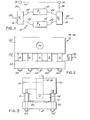
- a system 10 utilizing the diverter valve of the present invention is generally and schematically illustrated.
- a filter F1 and F2 is shown generally at 12 and 14, respectively.
- the filters 12 and 14 are interconnected to valves V1 and V2 shown generally at 16 and 18, respectively, through the utilization of appropriate conduits such as shown at 20 through 26.
- a desired material to be processed is applied through the conduit 28 to the inlet diverter valve 16 and leaves the outlet diverter valve 18 by way of the conduit 30 which, in turn, is connected to the desired processing equipment such as an extruder, spinnerette, mold, or the like (not shown).
- Valve operators 32 and 34 are connected as illustrated by the dashed lines 36 and 38 to the valves 16 and 18 to effect synchronous operation thereof (when such is desired) designated by the dashed line 40 interconnecting the operators 32 and 34.
- the diverter valve such as shown at 16 and 18 includes a manifold block 50 and a backing plate 52.
- a slider plate 54 is sandwiched between the manifold block 50 and the backing plate 52 and is adapted for reciprocal movement as illustrated by the arrow 56.
- a plurality of the tie rods 58 through 66 are disposed along the length of the slide plate 54 and are connected between the manifold block 50 and the backing plate 52.
- a similar plurality of tie rods are provided on the opposite side of the valve 16/18 as shown more fully in Fig. 5 at 58-66.
- a guide member or spacer S in the form of a bushing surrounds each of the tie rods for purposes to be more fully explained below.
- the manifold block has an inlet passageway 70 provided therein along with a pair of outlet passageways 72 and 74.
- a recess 76 is provided in the upper face 78 of the slide plate 54.
- the recess 76 is designed in such a way that when the slide plate is in one of its limit positions, it exactly coincides with openings or ports provided at the face 80 on the manifold block 50, such, for example, as the ports 82 and 84 for the passageways 70 and 74, respectively.
- the recess 76 would exactly cover the ports 82 and 86. Stops (not shown) may be provided to so position the slide plate.
- the backing plate 52 defines a recess 88 therein within which is received an insert 90 preferably of an aluminum-bronze alloy which is used as a bearing for the bottom surface 92 of the slide plate 54.
- the surfaces 78 and 80 of the slide plate 54 and manifold block 50, respectively, have applied thereto the desired flatnesses and finishes to effect the metal-to-metal seal so as to preclude the material being processed from leaking therebetween.
- Fig. 5 there is illustrated the upper surface of the slide plate 54 with the recess 76 therein along with the tie rods 58 through 68 and the ones on the opposite sides of the valve designated 58' through 68'.
- each of the tie rods is surrounded by the guide member S.
- Each of the guides or bushings is preferably constructed of an aluminum-bronze alloy and is in contact with the opposite side edges 94 and 96 parallel to each other, the slide plate 54 is accurately and properly positioned relative to the manifold block so that recess 76 always mates with ports 82 and either 84 or 86 depending upon the limit position of the slide plate 54.
Landscapes
- Engineering & Computer Science (AREA)
- Mechanical Engineering (AREA)
- General Engineering & Computer Science (AREA)
- Chemical & Material Sciences (AREA)
- Chemical Kinetics & Catalysis (AREA)
- Multiple-Way Valves (AREA)
- Sliding Valves (AREA)
- Superconductors And Manufacturing Methods Therefor (AREA)
Applications Claiming Priority (2)
| Application Number | Priority Date | Filing Date | Title |
|---|---|---|---|
| US06/139,307 US4334552A (en) | 1980-04-11 | 1980-04-11 | Diverter valve |
| US139307 | 1980-04-11 |
Publications (1)
| Publication Number | Publication Date |
|---|---|
| EP0037874A1 true EP0037874A1 (en) | 1981-10-21 |
Family
ID=22486031
Family Applications (1)
| Application Number | Title | Priority Date | Filing Date |
|---|---|---|---|
| EP81100764A Withdrawn EP0037874A1 (en) | 1980-04-11 | 1981-02-03 | Diverter valve |
Country Status (12)
| Country | Link |
|---|---|
| US (1) | US4334552A (enExample) |
| EP (1) | EP0037874A1 (enExample) |
| JP (1) | JPS56143869A (enExample) |
| KR (1) | KR830005521A (enExample) |
| BR (1) | BR8101452A (enExample) |
| DK (1) | DK46381A (enExample) |
| ES (1) | ES499147A0 (enExample) |
| FI (1) | FI810290A7 (enExample) |
| GR (1) | GR73546B (enExample) |
| IE (1) | IE810142L (enExample) |
| NO (1) | NO810287L (enExample) |
| PT (1) | PT72544B (enExample) |
Families Citing this family (12)
| Publication number | Priority date | Publication date | Assignee | Title |
|---|---|---|---|---|
| US4493476A (en) * | 1982-09-28 | 1985-01-15 | Strickland Reid A | Slide valve for controlling fluid flow |
| DE3335755A1 (de) * | 1983-10-01 | 1985-04-18 | Hansa Metallwerke Ag, 7000 Stuttgart | Brausenkopf |
| US4580759A (en) * | 1984-08-13 | 1986-04-08 | Combustion Engineering, Inc. | Multiple port, sliding plate valve |
| KR880005354A (ko) * | 1986-10-08 | 1988-06-28 | 나까무라 겐조 | 전자 작동기 |
| IT1210776B (it) * | 1987-06-01 | 1989-09-20 | Gevipi Ag | Cartuccia per rubinetto a piastrine in materiale duro con rivestimento metallico delle superfici di scorrimento |
| US5087483A (en) * | 1988-11-22 | 1992-02-11 | Masco Corporation | Carburizing ceramic plates for a faucet valve |
| US5295510A (en) * | 1992-08-21 | 1994-03-22 | Lci Corporation | Diverter valve |
| US5634953A (en) * | 1995-04-20 | 1997-06-03 | Cincinnati Milacron Inc. | Extruder venting system with vacuum shuttle valve |
| US6135145A (en) * | 1997-06-06 | 2000-10-24 | Maag Pump Systems Textron Inc. | Valve and filtration arrangement for polymer processing system |
| DE10030584A1 (de) * | 2000-06-21 | 2002-01-03 | Gneuss Kunststofftechnik Gmbh | Mehrweg-Drehschieber-Ventil zur Verteilung von hochmolekularen Polymer-Kunststoff-Schmelzen |
| DE10139620A1 (de) * | 2001-08-11 | 2003-02-27 | Bosch Gmbh Robert | Kraftstoffeinspritzventil für Brennkraftmaschinen und ein Verfahren zur Härtung desselben |
| JP4363283B2 (ja) * | 2004-09-13 | 2009-11-11 | 株式会社デンソー | 空気通路開閉装置 |
Citations (2)
| Publication number | Priority date | Publication date | Assignee | Title |
|---|---|---|---|---|
| GB672693A (en) * | 1948-02-13 | 1952-05-28 | Georges Henri Dion | Improvements in or relating to measuring instruments for physical quantities |
| US2951505A (en) * | 1957-07-08 | 1960-09-06 | Dynex Inc | Slide plate type hydraulic valve |
Family Cites Families (11)
| Publication number | Priority date | Publication date | Assignee | Title |
|---|---|---|---|---|
| US1855913A (en) * | 1928-05-14 | 1932-04-26 | Trico Products Corp | Windshield cleaner control |
| GB672963A (en) | 1947-07-03 | 1952-05-28 | Lang Pneumatic Ltd | Improvements in, or relating to, valves |
| US2950737A (en) * | 1958-02-20 | 1960-08-30 | Deere & Co | Fertilizer distributor |
| US3021823A (en) * | 1959-04-28 | 1962-02-20 | Stewart Warner Corp | Reciprocating air motor |
| US3521674A (en) * | 1968-06-24 | 1970-07-28 | Beckman Instruments Inc | Sampling valve |
| US3683965A (en) * | 1970-04-08 | 1972-08-15 | Materials Technology Corp | Adjustable choke valve |
| US3661357A (en) * | 1970-06-01 | 1972-05-09 | United States Steel Corp | Dust valve |
| US3960361A (en) * | 1975-03-14 | 1976-06-01 | Bertea Corporation | Solenoid valve |
| JPS5263812A (en) * | 1975-11-21 | 1977-05-26 | Hitachi Ltd | Martensitic stainless steel for nitriding |
| JPS52138027A (en) * | 1976-04-08 | 1977-11-17 | Nissan Motor | Ferrous member superior in initial fitting and wear resisting property and production process therefor |
| US4204886A (en) * | 1979-04-24 | 1980-05-27 | Kolene Corp. | Method for improving and article having improved wear resistance |
-
1980
- 1980-04-11 US US06/139,307 patent/US4334552A/en not_active Expired - Lifetime
-
1981
- 1981-01-27 IE IE810142A patent/IE810142L/xx unknown
- 1981-01-28 NO NO810287A patent/NO810287L/no unknown
- 1981-02-02 FI FI810290A patent/FI810290A7/fi not_active Application Discontinuation
- 1981-02-03 DK DK46381A patent/DK46381A/da unknown
- 1981-02-03 EP EP81100764A patent/EP0037874A1/en not_active Withdrawn
- 1981-02-05 ES ES499147A patent/ES499147A0/es active Granted
- 1981-02-07 KR KR1019810000386A patent/KR830005521A/ko active Pending
- 1981-02-19 PT PT72544A patent/PT72544B/pt unknown
- 1981-02-28 JP JP2769181A patent/JPS56143869A/ja active Pending
- 1981-03-03 GR GR64295A patent/GR73546B/el unknown
- 1981-03-12 BR BR8101452A patent/BR8101452A/pt unknown
Patent Citations (2)
| Publication number | Priority date | Publication date | Assignee | Title |
|---|---|---|---|---|
| GB672693A (en) * | 1948-02-13 | 1952-05-28 | Georges Henri Dion | Improvements in or relating to measuring instruments for physical quantities |
| US2951505A (en) * | 1957-07-08 | 1960-09-06 | Dynex Inc | Slide plate type hydraulic valve |
Also Published As
| Publication number | Publication date |
|---|---|
| PT72544A (en) | 1981-03-01 |
| NO810287L (no) | 1981-10-12 |
| ES8205987A1 (es) | 1982-06-16 |
| FI810290L (fi) | 1981-10-12 |
| GR73546B (enExample) | 1984-03-13 |
| KR830005521A (ko) | 1983-08-20 |
| PT72544B (en) | 1982-03-11 |
| DK46381A (da) | 1981-10-12 |
| IE810142L (en) | 1981-10-11 |
| BR8101452A (pt) | 1981-10-13 |
| US4334552A (en) | 1982-06-15 |
| JPS56143869A (en) | 1981-11-09 |
| ES499147A0 (es) | 1982-06-16 |
| FI810290A7 (fi) | 1981-10-12 |
Similar Documents
| Publication | Publication Date | Title |
|---|---|---|
| US4334552A (en) | Diverter valve | |
| DE69700357T2 (de) | Vorrichtung und Verfahren zum abgelenkten Abdichten | |
| US4506696A (en) | Gas tight plug valve | |
| DE1288392B (de) | Drehschieber | |
| EP2512773B1 (de) | Verstellbare düse | |
| US10828820B2 (en) | Extrusion die systems, die changers, and related methods | |
| US5147195A (en) | Extrusion apparatus with adjustable flow-restricting member | |
| KR102275236B1 (ko) | 중점도 내지 고점도 유체용 회전 스크린 필터링 장치 및 이를 위한 밀봉 및 실장 방법 | |
| KR102167818B1 (ko) | 밀봉 디바이스를 갖는 여과 장치 | |
| US3163175A (en) | Precision adjustable control valve assembly | |
| DE69427646T2 (de) | Dichtung für eine vorrichtung zum filtrieren von polymeren | |
| US4084783A (en) | Molding tool for making valve | |
| KR101906176B1 (ko) | 배관의 홈 가공 장치 및 이를 이용한 가공 방법 | |
| KR20240095515A (ko) | 체크 밸브 | |
| US3833121A (en) | Plastic filtration systems | |
| WO2001086177A1 (de) | Anwendungsgebiet und stand der technik | |
| DE19831540A1 (de) | Partielle Veränderung des Fließkanalquerschnitts eines geschlossenen Strömungskanalquerschnitts | |
| US20230356449A1 (en) | Modular fluid processing apparatuses, modular components and related methods | |
| DE69619375T2 (de) | Aktive, automatische klemmkraftregelung | |
| DE3833220A1 (de) | Spritzgiesswerkzeug zur verarbeitung thermoplastischer kunststoffe | |
| EP3353519A1 (de) | Kanalsystem für eine leitungskomponente einer prozesstechnischen anlage, system zum detektieren einer prozessmediumsleckage und leitungskomponente der prozesstechnischen anlage | |
| EP0483236B1 (en) | Rotary diverter valve having flat valve interfaces | |
| EP0841142B1 (de) | Spritzgussform | |
| DE10231920A1 (de) | Mehrlagen-Membran | |
| US5295510A (en) | Diverter valve |
Legal Events
| Date | Code | Title | Description |
|---|---|---|---|
| PUAI | Public reference made under article 153(3) epc to a published international application that has entered the european phase |
Free format text: ORIGINAL CODE: 0009012 |
|
| AK | Designated contracting states |
Designated state(s): BE DE FR GB LU NL |
|
| STAA | Information on the status of an ep patent application or granted ep patent |
Free format text: STATUS: THE APPLICATION IS DEEMED TO BE WITHDRAWN |
|
| 18D | Application deemed to be withdrawn |
Effective date: 19820927 |
|
| RIN1 | Information on inventor provided before grant (corrected) |
Inventor name: BLANCHARD, ROBERT RAYMOND |