EP0037614A1 - Machine for shaping roofing means out of concrete by extrusion - Google Patents
Machine for shaping roofing means out of concrete by extrusion Download PDFInfo
- Publication number
- EP0037614A1 EP0037614A1 EP81200376A EP81200376A EP0037614A1 EP 0037614 A1 EP0037614 A1 EP 0037614A1 EP 81200376 A EP81200376 A EP 81200376A EP 81200376 A EP81200376 A EP 81200376A EP 0037614 A1 EP0037614 A1 EP 0037614A1
- Authority
- EP
- European Patent Office
- Prior art keywords
- shaping
- frame
- stationary frame
- transverse
- machine according
- Prior art date
- Legal status (The legal status is an assumption and is not a legal conclusion. Google has not performed a legal analysis and makes no representation as to the accuracy of the status listed.)
- Granted
Links
Images

Classifications
-
- B—PERFORMING OPERATIONS; TRANSPORTING
- B28—WORKING CEMENT, CLAY, OR STONE
- B28B—SHAPING CLAY OR OTHER CERAMIC COMPOSITIONS; SHAPING SLAG; SHAPING MIXTURES CONTAINING CEMENTITIOUS MATERIAL, e.g. PLASTER
- B28B1/00—Producing shaped prefabricated articles from the material
- B28B1/29—Producing shaped prefabricated articles from the material by profiling or strickling the material in open moulds or on moulding surfaces
Definitions
- Machine for shaping roofing means out of concrete by extrusion in which each roofing means at one end is provided with an integral flange portion that is substantially perpendicular to the main direction of the roofing means and in which metal under-moulds are used each comprising a main portion shaping the lower side of the roofing means, a transverse portion at one end of said main portion shaping the innerside of said flange portion and a flange at the lower end of said transvere portion shaping the lower part of said flange portion.
- a machine used therefore comprises in general a horizontally extending conveyor track, in which under-moulds, so-called pallets, linked one behind the other are moved along with the aid/conveyor chains or such.
- a shaing box is mounted with the reservoir for mortar, a mixing roller, a shaing roller and a doctor plate. This doctor plate together with the shaping roller takes care of the shaping of the upper face of the tiles.
- the lower side of the tiles indeed have projections in cross-direction, such as suspension bosses. These bosses are molded by appropriate recesses in the under-moulds. These projections only have a restricted height and do not give difficulties.
- roofing means in the shape of the gable tiles, these are tiles with a flange at one of its longitudinal sides,thus extending in/extrusion direction, can be made in a satisfactory way it is not possible to shape with the aid of such a device roofing means having a flange transverse to the extrusion direction.
- roofing means are chaperon tiles, under-tiles, first ridge tiles and end ridge tiles.
- roofing means with a flange along a longitudinal side and a flange along the upper or lower side, in fact in combination of gable tiles and chperon tiles or under-tiles.
- Chaperon tiles so tiles with a flange along the upper side, are used to finish pent-roofs that are applied more and more.
- roofing means provided with a transverse flange cannot be shaped by the normal continuously working machine because of the fact that the filling and the compacting of the mortar into the moulding cavity, delimiting the transverse flange, is not satisfactory.
- the main reason is that the moving pallet cannot be supported in a sufficient exact manner with regard to the transverse wall, that delimites the outer side of the flange portion and cannot be integral with the pallet. If this would be the case then the shaped roofing means cannot be released from the pallet.
- roofing means manually with flange portions of course indeed with mechanical auxiliary means. It will be clear that the shaping of roofing means is very labour intensive and therefore expensive and that moreover the quality depends strongly on the attention and skil of the labourer.
- the invention aims to provide a machine with the aid of which roofing means with flange portions can be shaped mechanically.
- the objections of the manual shaping method are removed according to which in a manual the shaping cavity for the flange portion has to be filled and compacted.
- the machine according to the invention is characterized in that the machine comprises a horizontal oblong stationary frame and in it in series a number of stations for shaping at a time onr roofing means, each station comprises side walls and transverse walls in which an under-mould can be fitted and comprises supports for supporting the undermould in vertical direction in such a manner that the shaping cavity for the flange portion is defined by the innerside of a transverse wall of the staion in said frame, the outerside of the transverse portion of the undermould and the upperside of the flange of the undermould, said machine further comprises movable frame, that can be displaced along the stationary frame and that is provided with means to fill all stations in one step with mortar to compact and to shape its upperside.
- the machine according to the application comprises a stationary frame and amovable frame.
- the stationary frame is oblong, extends in horizontal direction and comprises a number of substantially horizontally extending parallel longitudinal rails, supported by legs.
- the legs are indicated by 1 and a number of longitudinal rails are indicated by 2 and 3 resp.
- each under-mould comprises an in general horizontally extending profiled main part 4a, a transverse part 4d destined to shape one side of the flange portion of the roofing means and a flange 4c destined to shape the lower edge of the flange portion.
- Each under-mould 4 fits between two vertical transverse walls 5 and two vertical side walls 6 6 of the stationary frame. It will be clear that the upper limit of each transverse wall 5 has to be adapted to the curvature of the roofing means to be shaped.
- each shaping station is formed by two U-beams 7 extending along the length of the stationary frame.
- supports 8 are mounted on which the longitudinal axes of the under-mould 4 are supported when the under-mould is postioned on its place in the stationary frame.
- each under-mould is fittingly enclosed by the transverse walls 5 and the side walls 6 and is supported in vertical direction by the supports 8. It will be clear that still more supports can be provided, for instance on the transverse walls 5, so that each under-mould also is supported at both or at one head end.
- each station pneumatic lifting means 9 are present which are able to move the under-mould 4 vertically upwards from its place in a stationary frame (see fig. 1).
- the movable frame is indicated by 20 and is supported at one side with the aid of rollers 21 by the square longitudinal beam 2 of the stationary frame and at the other side by rollers 22 resting on the U-beam 3 of the stationary frame.
- a rack 23 is mounted along which a pinion can roll. This pinion is driven with the aid of motor 25 that moves together with the movable frame 20.
- the movable frame 20 comprises essentially a shaping box 26 in which from a hopper mortar can be casted. During the filling of the shaping box 26 the movable frame 20 is at one end of the stationary frame. It will be celar that therefore that stationary frame hs to be provided with a blind part. At the other end also a blind part is present above which the frame 20 is present in case the whole extrudate is extrudated.
- a second motor 27 drives through a chain 27a or such the shaping roller 28. From this shaping roller 28 through a second chain 29 or such a shaft 30 is driven that is provided with pins or such that are meant to keep the concrete mortar in movement and to press it below the shaping roller 28.
- a second chain 29 or such a shaft 30 is driven that is provided with pins or such that are meant to keep the concrete mortar in movement and to press it below the shaping roller 28.
- the shaping box 26 is limited at its side edges by side walls moving slidingly over longitudinal strips 6, while the front side is delimited by a cover plate indicated by 31 and at the back a doctor plate 32 is present, of which the lower edge determines the final upper shape of the roofing means to be shaped.
- This plate 32 together with the upperside of the row of under-moulds 4 forms the extrusion mouth for the extrudate.
- the frame 20 is present above the blind portion at one end of the stationary frame.
- the filling station not shown, is at the right hand side of the drawing.
- the drive motor 27 for the shaping roller 28 and the mixing shaft 30 are put into action.
- the mortar comes at the right hand side in figure 1 out of the shaping box 26 through the extrusion mouth.
- the mortar is pressed by the shaping roller 28 into the under-moulds 4 and also in the cavity of each flange portion.
- the compacting of the mortar also is caused by the shaping roller 28 while the lower edge of teh doctor plate 32 wipes the upper side of the extrudate.
- the shaped extrudate has to be devided on the spot of the transverse walls 5.
- one or more vertical moving cutting devices 33 see fig. 2, are used.
- the or each cutting device 33 comprises two parallel cutting knifes 34 so between the cutting knifes a space is present.
- the cutting of teh extrudate preferable takes place after the shaping of the whole extrudate so when the frame 20 is above the left hand blind portion.
- each under-mould 4 is moved upwardly and can be taken off so that the roofing means shaped thereon can be dried in a drying device after which the roofing means can be taken from the under-mould.
- the'capacity of the device can be increased by shaping a number of series roofing means next to each other in one step.
Abstract
Description
- Machine for shaping roofing means out of concrete by extrusion in which each roofing means at one end is provided with an integral flange portion that is substantially perpendicular to the main direction of the roofing means and in which metal under-moulds are used each comprising a main portion shaping the lower side of the roofing means, a transverse portion at one end of said main portion shaping the innerside of said flange portion and a flange at the lower end of said transvere portion shaping the lower part of said flange portion.
- At present it is general practice to shape tiles out of concrete. A machine used therefore comprises in general a horizontally extending conveyor track, in which under-moulds, so-called pallets, linked one behind the other are moved along with the aid/conveyor chains or such. Above the pallet in a determined position a shaing box is mounted with the reservoir for mortar, a mixing roller, a shaing roller and a doctor plate. This doctor plate together with the shaping roller takes care of the shaping of the upper face of the tiles.
- On the upperside of the tiles no projections in cross direction are present for this is not possible in an extrusion method.
- The lower side of the tiles indeed have projections in cross-direction, such as suspension bosses. These bosses are molded by appropriate recesses in the under-moulds. These projections only have a restricted height and do not give difficulties.
- Though with such a machine not only concrete tiles but also roofing means in the shape of the gable tiles, these are tiles with a flange at one of its longitudinal sides,thus extending in/extrusion direction, can be made in a satisfactory way it is not possible to shape with the aid of such a device roofing means having a flange transverse to the extrusion direction. Examples of such roofing means are chaperon tiles, under-tiles, first ridge tiles and end ridge tiles. Also still exist roofing means with a flange along a longitudinal side and a flange along the upper or lower side, in fact in combination of gable tiles and chperon tiles or under-tiles.
- Chaperon tiles, so tiles with a flange along the upper side, are used to finish pent-roofs that are applied more and more.
- Under-tiles, so tiles with a flange along the lower side, are used to seal of the lower edge of a roof, among others against entering by birds and against looking in to the lower tile lath.
- In both cases it was also possible to use normal tiles and to finish the edge with the aid of wood or mortar. This is expensive because of the maintenance and is not so nice respectively.
- The demand for roofing means becomes greater and greater.
- Roofing means provided with a transverse flange cannot be shaped by the normal continuously working machine because of the fact that the filling and the compacting of the mortar into the moulding cavity, delimiting the transverse flange, is not satisfactory. The main reason is that the moving pallet cannot be supported in a sufficient exact manner with regard to the transverse wall, that delimites the outer side of the flange portion and cannot be integral with the pallet. If this would be the case then the shaped roofing means cannot be released from the pallet.
- Another reason is that no sufficient time is available to transmit sufficient mortar in the shaping cavity of the flange portion and to compact it.
- Until now one has been urged to shape roofing means manually with flange portions of course indeed with mechanical auxiliary means. It will be clear that the shaping of roofing means is very labour intensive and therefore expensive and that moreover the quality depends strongly on the attention and skil of the labourer.
- The invention aims to provide a machine with the aid of which roofing means with flange portions can be shaped mechanically. By this the objections of the manual shaping method are removed according to which in a manual the shaping cavity for the flange portion has to be filled and compacted.
- The machine according to the invention is characterized in that the machine comprises a horizontal oblong stationary frame and in it in series a number of stations for shaping at a time onr roofing means, each station comprises side walls and transverse walls in which an under-mould can be fitted and comprises supports for supporting the undermould in vertical direction in such a manner that the shaping cavity for the flange portion is defined by the innerside of a transverse wall of the staion in said frame, the outerside of the transverse portion of the undermould and the upperside of the flange of the undermould, said machine further comprises movable frame, that can be displaced along the stationary frame and that is provided with means to fill all stations in one step with mortar to compact and to shape its upperside.
- A number of roofing means so are shaped in series in one step, by which the speed of production also is substantially higher than with the manual shaping method, while moreover by the measures to be described below, the quality of the flange portion is constant and good.
- The invention will be described in more detail with the aid of the drawing in which an example is given.
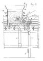
- Figure 1 shows in perspectif and schematically a view of the machine according to the invention.
- Figure 2 shows a longitudinal section over a part of the machine according to the invention on larger scale.
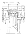
- Figure 3 shows a cross-section along the line III-III in fig. 2.
- The machine according to the application comprises a stationary frame and amovable frame. The stationary frame is oblong, extends in horizontal direction and comprises a number of substantially horizontally extending parallel longitudinal rails, supported by legs. The legs are indicated by 1 and a number of longitudinal rails are indicated by 2 and 3 resp.
- In the stationary frame in length direction of the frame one behind the other a number of stations is present for shaping at the time onre roofing means. It is for instance possible to provide a machine with 7 such stations. However, it will be clear that this number is completely arbitrary. In figure 2 one of such stations is shown completely while both adjoining stations are shown partly.
- As is the case with the manual method for shaping roofing means under-moulds of aluminium or such material are used. These under-moulds, the so-called pallets, are indicated in the drawing by 4. The under-moulds are of known construction and are completely adapted for shaping the lower side of the roofing means to be formed. Each under-mould comprises an in general horizontally extending profiled main part 4a, a transverse part 4d destined to shape one side of the flange portion of the roofing means and a
flange 4c destined to shape the lower edge of the flange portion. - Each under-
mould 4 fits between two verticaltransverse walls 5 and twovertical side walls 6 6 of the stationary frame. It will be clear that the upper limit of eachtransverse wall 5 has to be adapted to the curvature of the roofing means to be shaped. - The
side walls 6 of each shaping station are formed by twoU-beams 7 extending along the length of the stationary frame. On theside walls 6supports 8 are mounted on which the longitudinal axes of the under-mould 4 are supported when the under-mould is postioned on its place in the stationary frame. - In this way each under-mould is fittingly enclosed by the
transverse walls 5 and theside walls 6 and is supported in vertical direction by thesupports 8. It will be clear that still more supports can be provided, for instance on thetransverse walls 5, sothat each under-mould also is supported at both or at one head end. - Below each station pneumatic lifting means 9 are present which are able to move the under-
mould 4 vertically upwards from its place in a stationary frame (see fig. 1). - The movable frame is indicated by 20 and is supported at one side with the aid of
rollers 21 by the squarelongitudinal beam 2 of the stationary frame and at the other side byrollers 22 resting on theU-beam 3 of the stationary frame. Along the U-beam 3 over the whole length of teh stationary frame arack 23 is mounted along which a pinion can roll. This pinion is driven with the aid ofmotor 25 that moves together with themovable frame 20. - It will be clear that in case the
motor 25 drives thepinion 24 themovable frame 20 will move along the stationary frame. - The
movable frame 20 comprises essentially ashaping box 26 in which from a hopper mortar can be casted. During the filling of theshaping box 26 themovable frame 20 is at one end of the stationary frame. It will be celar that therefore that stationary frame hs to be provided with a blind part. At the other end also a blind part is present above which theframe 20 is present in case the whole extrudate is extrudated. - On the
frame 20 still asecond motor 27 is present, see figure 1. Thissecond motor 27 drives through achain 27a or such theshaping roller 28. From this shapingroller 28 through asecond chain 29 or such ashaft 30 is driven that is provided with pins or such that are meant to keep the concrete mortar in movement and to press it below theshaping roller 28. Such a construction is known per se for a machine for shaping ordinary tiles, so tiles with flange parts. - It will be clear that the mortar is not allowed to spread freely over the stations. Therefore the
shaping box 26 is limited at its side edges by side walls moving slidingly overlongitudinal strips 6, while the front side is delimited by a cover plate indicated by 31 and at the back adoctor plate 32 is present, of which the lower edge determines the final upper shape of the roofing means to be shaped. - This
plate 32 together with the upperside of the row of under-moulds 4 forms the extrusion mouth for the extrudate. - During the filling of the
shaping box 26 with mortar theframe 20 is present above the blind portion at one end of the stationary frame. In fig. 1 the filling station, not shown, is at the right hand side of the drawing. - When the
moulding box 26 is sufficiently filled with mortar the frame moves with the aid ofmotor 25 to the left in the direction of arrow A in figures 1 and 2. - The
drive motor 27 for the shapingroller 28 and the mixingshaft 30 are put into action. The mortar comes at the right hand side in figure 1 out of theshaping box 26 through the extrusion mouth. The mortar is pressed by the shapingroller 28 into the under-moulds 4 and also in the cavity of each flange portion. - The compacting of the mortar also is caused by the shaping
roller 28 while the lower edge of tehdoctor plate 32 wipes the upper side of the extrudate. - To take care of the fact that also the shaping cavities for the flange portions are filled and compacted in a sufficient manner for a sufficient supply of mortar has to be taken care. By driving the shaping
roller 28 at a sufficient speed of rotation this can be obtained. It will be obvious that this speed of rotation of the shapingroller 28 depends on the speed of movement of theframe 20. - When the whole extrudate is shaped the
frame 20 arrives above the left blind portion of teh stationary frame and is stopped. - Now the shaped extrudate has to be devided on the spot of the
transverse walls 5. For this one or more vertical movingcutting devices 33, see fig. 2, are used. - The or each cutting
device 33 comprises two parallel cutting knifes 34 so between the cutting knifes a space is present. - When the cutting
device 33 is moved from the position indicated in fig. 2 to a lower position the extrudate is cut at both sides of tehtransverse wall 5. The material of the extrudate present on the upper side of thetransverse wall 5 will be taken up in the space between both cutting knifes and removed at the moment the cuttingdevice 33 moves up again. - The cutting of teh extrudate preferable takes place after the shaping of the whole extrudate so when the
frame 20 is above the left hand blind portion. - With the aid of a mechanism then at the same time all cutting
devices 33 can be moved upwardly and downwardly again. It is also possible to use only onecutting device 33 that subsequently executes all cutting steps and so moves along the stationary frame. - At the moment the extrudate is cut lifting means 9 take care that each under-
mould 4 is moved upwardly and can be taken off sothat the roofing means shaped thereon can be dried in a drying device after which the roofing means can be taken from the under-mould. - It will be obvious that the'capacity of the device can be increased by shaping a number of series roofing means next to each other in one step.
Claims (8)
Priority Applications (1)
| Application Number | Priority Date | Filing Date | Title |
|---|---|---|---|
| AT81200376T ATE3383T1 (en) | 1980-04-03 | 1981-04-02 | MACHINE FOR FORMING CONCRETE DACHSTONE MOLDINGS BY EXTRUSION. |
Applications Claiming Priority (2)
| Application Number | Priority Date | Filing Date | Title |
|---|---|---|---|
| NL8002000A NL8002000A (en) | 1980-04-03 | 1980-04-03 | APPARATUS FOR EXTRUSION FORMING CONCRETE ATTACHMENTS FOR ROOFING. |
| NL8002000 | 1980-04-03 |
Publications (2)
| Publication Number | Publication Date |
|---|---|
| EP0037614A1 true EP0037614A1 (en) | 1981-10-14 |
| EP0037614B1 EP0037614B1 (en) | 1983-05-18 |
Family
ID=19835115
Family Applications (1)
| Application Number | Title | Priority Date | Filing Date |
|---|---|---|---|
| EP81200376A Expired EP0037614B1 (en) | 1980-04-03 | 1981-04-02 | Machine for shaping roofing means out of concrete by extrusion |
Country Status (4)
| Country | Link |
|---|---|
| EP (1) | EP0037614B1 (en) |
| AT (1) | ATE3383T1 (en) |
| DE (1) | DE3160304D1 (en) |
| NL (1) | NL8002000A (en) |
Citations (4)
| Publication number | Priority date | Publication date | Assignee | Title |
|---|---|---|---|---|
| US2734249A (en) * | 1956-02-14 | Roofing tile making machines | ||
| FR1133225A (en) * | 1954-10-22 | 1957-03-25 | Device for compressing concrete parts to be manufactured in formwork | |
| US3122812A (en) * | 1961-04-04 | 1964-03-03 | Frank A Gory | Tile manufacturing machine |
| US3193903A (en) * | 1962-05-11 | 1965-07-13 | Nordon Inc | Tile casting installation |
-
1980
- 1980-04-03 NL NL8002000A patent/NL8002000A/en not_active Application Discontinuation
-
1981
- 1981-04-02 EP EP81200376A patent/EP0037614B1/en not_active Expired
- 1981-04-02 DE DE8181200376T patent/DE3160304D1/en not_active Expired
- 1981-04-02 AT AT81200376T patent/ATE3383T1/en active
Patent Citations (4)
| Publication number | Priority date | Publication date | Assignee | Title |
|---|---|---|---|---|
| US2734249A (en) * | 1956-02-14 | Roofing tile making machines | ||
| FR1133225A (en) * | 1954-10-22 | 1957-03-25 | Device for compressing concrete parts to be manufactured in formwork | |
| US3122812A (en) * | 1961-04-04 | 1964-03-03 | Frank A Gory | Tile manufacturing machine |
| US3193903A (en) * | 1962-05-11 | 1965-07-13 | Nordon Inc | Tile casting installation |
Also Published As
| Publication number | Publication date |
|---|---|
| NL8002000A (en) | 1981-11-02 |
| EP0037614B1 (en) | 1983-05-18 |
| DE3160304D1 (en) | 1983-07-07 |
| ATE3383T1 (en) | 1983-06-15 |
Similar Documents
| Publication | Publication Date | Title |
|---|---|---|
| CA2467250C (en) | Installation for producing reinforced concrete parts | |
| EP0037614A1 (en) | Machine for shaping roofing means out of concrete by extrusion | |
| BG61685B1 (en) | Machine and method for the production of roof tiles | |
| US5080840A (en) | Method and apparatus for the manufacture of roof covering plates having a transverse flange | |
| CN112659326B (en) | Intelligent building brick manufacturing device | |
| CN211241484U (en) | A roll cutting machine for face skin production | |
| CN101489745B (en) | Door core producing mould | |
| US4381907A (en) | Apparatus for manufacturing insulating construction profiles | |
| ITMI20002537A1 (en) | PRESS FOR THE PRODUCTION OF TILES EQUIPPED WITH BELT LOADING DEVICES | |
| US4102618A (en) | Manufacturing benches for moulded construction | |
| CA1044434A (en) | Apparatus for the production of castings | |
| GB2217170A (en) | Continuous process baking machines | |
| EP0015614A1 (en) | Method and device for the manufacture of cleaving tiles and cleaving tile obtained | |
| GB1590330A (en) | Manufacture of building blocks such as bricks | |
| CN214934186U (en) | Insulation board wall board blanking device | |
| US3584354A (en) | Machine for moulding the short sides of building elements having a u-shaped cross section | |
| CN219991510U (en) | Manual soap cutting device | |
| CN113119291B (en) | Foam concrete prefabrication demoulding device and demoulding method thereof | |
| US2104293A (en) | Brick and tile machine | |
| JPH0550419A (en) | Device for molding tile with groove | |
| US1695132A (en) | Apparatus for the manufacture of roofing tiles | |
| SU28825A1 (en) | Press for the manufacture of heat-concrete stones with internal channels closed at both ends | |
| US4150933A (en) | Apparatus for molding roofing panels having a stepped portion | |
| RU2037400C1 (en) | Apparatus for molding products from construction materials | |
| EP0778112B1 (en) | Process for making wall elements |
Legal Events
| Date | Code | Title | Description |
|---|---|---|---|
| PUAI | Public reference made under article 153(3) epc to a published international application that has entered the european phase |
Free format text: ORIGINAL CODE: 0009012 |
|
| AK | Designated contracting states |
Designated state(s): AT BE CH DE FR IT NL SE |
|
| 17P | Request for examination filed |
Effective date: 19811019 |
|
| GRAA | (expected) grant |
Free format text: ORIGINAL CODE: 0009210 |
|
| AK | Designated contracting states |
Designated state(s): AT BE CH DE FR IT LI NL SE |
|
| PG25 | Lapsed in a contracting state [announced via postgrant information from national office to epo] |
Ref country code: SE Free format text: THE PATENT HAS BEEN ANNULLED BY A DECISION OF A NATIONAL AUTHORITY Effective date: 19830518 Ref country code: LI Effective date: 19830518 Ref country code: IT Free format text: LAPSE BECAUSE OF FAILURE TO SUBMIT A TRANSLATION OF THE DESCRIPTION OR TO PAY THE FEE WITHIN THE PRESCRIBED TIME-LIMIT;WARNING: LAPSES OF ITALIAN PATENTS WITH EFFECTIVE DATE BEFORE 2007 MAY HAVE OCCURRED AT ANY TIME BEFORE 2007. THE CORRECT EFFECTIVE DATE MAY BE DIFFERENT FROM THE ONE RECORDED. Effective date: 19830518 Ref country code: FR Free format text: THE PATENT HAS BEEN ANNULLED BY A DECISION OF A NATIONAL AUTHORITY Effective date: 19830518 Ref country code: CH Effective date: 19830518 |
|
| REF | Corresponds to: |
Ref document number: 3383 Country of ref document: AT Date of ref document: 19830615 Kind code of ref document: T |
|
| PG25 | Lapsed in a contracting state [announced via postgrant information from national office to epo] |
Ref country code: AT Effective date: 19830601 |
|
| REF | Corresponds to: |
Ref document number: 3160304 Country of ref document: DE Date of ref document: 19830707 |
|
| REG | Reference to a national code |
Ref country code: CH Ref legal event code: PL |
|
| EN | Fr: translation not filed | ||
| PLBE | No opposition filed within time limit |
Free format text: ORIGINAL CODE: 0009261 |
|
| STAA | Information on the status of an ep patent application or granted ep patent |
Free format text: STATUS: NO OPPOSITION FILED WITHIN TIME LIMIT |
|
| 26N | No opposition filed | ||
| PGFP | Annual fee paid to national office [announced via postgrant information from national office to epo] |
Ref country code: NL Payment date: 19900430 Year of fee payment: 10 |
|
| PGFP | Annual fee paid to national office [announced via postgrant information from national office to epo] |
Ref country code: BE Payment date: 19910529 Year of fee payment: 11 |
|
| PG25 | Lapsed in a contracting state [announced via postgrant information from national office to epo] |
Ref country code: NL Effective date: 19911101 |
|
| NLV4 | Nl: lapsed or anulled due to non-payment of the annual fee | ||
| PG25 | Lapsed in a contracting state [announced via postgrant information from national office to epo] |
Ref country code: BE Effective date: 19920430 |
|
| BERE | Be: lapsed |
Owner name: REDLAND-BRAAS-BREDERO EUROPA RBB B.V. Effective date: 19920430 |
|
| PGFP | Annual fee paid to national office [announced via postgrant information from national office to epo] |
Ref country code: DE Payment date: 19990420 Year of fee payment: 19 |
|
| PG25 | Lapsed in a contracting state [announced via postgrant information from national office to epo] |
Ref country code: DE Free format text: LAPSE BECAUSE OF NON-PAYMENT OF DUE FEES Effective date: 20010201 |