EP0037558A2 - Übungsgerät - Google Patents
Übungsgerät Download PDFInfo
- Publication number
- EP0037558A2 EP0037558A2 EP81102454A EP81102454A EP0037558A2 EP 0037558 A2 EP0037558 A2 EP 0037558A2 EP 81102454 A EP81102454 A EP 81102454A EP 81102454 A EP81102454 A EP 81102454A EP 0037558 A2 EP0037558 A2 EP 0037558A2
- Authority
- EP
- European Patent Office
- Prior art keywords
- rope
- members
- bar
- exercise
- recited
- Prior art date
- Legal status (The legal status is an assumption and is not a legal conclusion. Google has not performed a legal analysis and makes no representation as to the accuracy of the status listed.)
- Granted
Links
Images


Classifications
-
- A—HUMAN NECESSITIES
- A63—SPORTS; GAMES; AMUSEMENTS
- A63B—APPARATUS FOR PHYSICAL TRAINING, GYMNASTICS, SWIMMING, CLIMBING, OR FENCING; BALL GAMES; TRAINING EQUIPMENT
- A63B21/00—Exercising apparatus for developing or strengthening the muscles or joints of the body by working against a counterforce, with or without measuring devices
- A63B21/16—Supports for anchoring force-resisters
- A63B21/1618—Supports for anchoring force-resisters on a door or a door frame
- A63B21/1627—Supports for anchoring force-resisters on a door or a door frame for anchoring on or between the vertical posts of a door frame
-
- A—HUMAN NECESSITIES
- A63—SPORTS; GAMES; AMUSEMENTS
- A63B—APPARATUS FOR PHYSICAL TRAINING, GYMNASTICS, SWIMMING, CLIMBING, OR FENCING; BALL GAMES; TRAINING EQUIPMENT
- A63B21/00—Exercising apparatus for developing or strengthening the muscles or joints of the body by working against a counterforce, with or without measuring devices
- A63B21/00181—Exercising apparatus for developing or strengthening the muscles or joints of the body by working against a counterforce, with or without measuring devices comprising additional means assisting the user to overcome part of the resisting force, i.e. assisted-active exercising
-
- A—HUMAN NECESSITIES
- A63—SPORTS; GAMES; AMUSEMENTS
- A63B—APPARATUS FOR PHYSICAL TRAINING, GYMNASTICS, SWIMMING, CLIMBING, OR FENCING; BALL GAMES; TRAINING EQUIPMENT
- A63B21/00—Exercising apparatus for developing or strengthening the muscles or joints of the body by working against a counterforce, with or without measuring devices
- A63B21/012—Exercising apparatus for developing or strengthening the muscles or joints of the body by working against a counterforce, with or without measuring devices using frictional force-resisters
- A63B21/018—Exercising apparatus for developing or strengthening the muscles or joints of the body by working against a counterforce, with or without measuring devices using frictional force-resisters including a rope or other flexible element moving relative to the surface of elements
-
- A—HUMAN NECESSITIES
- A63—SPORTS; GAMES; AMUSEMENTS
- A63B—APPARATUS FOR PHYSICAL TRAINING, GYMNASTICS, SWIMMING, CLIMBING, OR FENCING; BALL GAMES; TRAINING EQUIPMENT
- A63B21/00—Exercising apparatus for developing or strengthening the muscles or joints of the body by working against a counterforce, with or without measuring devices
- A63B21/00058—Mechanical means for varying the resistance
- A63B21/00069—Setting or adjusting the resistance level; Compensating for a preload prior to use, e.g. changing length of resistance or adjusting a valve
Definitions
- the present invention relates generally to exercise devices and more specifically to a mono-kinetic exercise device for mounting in a rectangular frame.
- Exercise devices have existed in various forms almost since the beginning of history. They have ranged from a tree limb for doing pullups or chinups to modern medical exercisers and weight machines of immense complexity.
- One of the main means of exercising the body is by exerting the muscles to move an object in space against resistance.
- the most commom application of this sort of exercise is in weight lifting, wherein a barbell loaded with the desired amount of weight is lifted and manipulated.
- Variations on this theme are numerous and include such items as weights attached to pulleys, which are pulled upwards by the use of ropes, and tension bars.
- Each of these devices utilizes the friction between a rope or elongated fabric against a surface to provide the resistance to movement required for proper muscle exertion.
- the means by which the friction is provided is different and the type of exercise for which the specific device is designed varies.
- an exercise device for mounting within a generally rectangular frame comprising:
- An advantage of the present invention is that it is rugged and inexpensive.
- a further advantage of the present invention is that it is easily mounted and removed from an ordinary door frame or similar frame.
- Yet another advantage of the present invention is that the easily adjusted tensioning means provides that the tension and the resistance to movement can be tailored for the particular user, and can be gradually increased as the user becomes stronger.
- Yet another advantage of the present invention is that the grasping bar remains balanced from side to side regardless of usage.
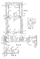
- Figs. 1 - 4 illustrate a first embodiment of an exercise device of the present invention referred to by the general reference character 5.
- Fig. 1 there is shown a door frame having sides 6 and 8. Near the top of the frame are two mounting brackets, generally designated 10 and 12, while another pair of brackets, designated 14 and 16, are located near the bottom of the frame.
- the brackets 10 and 14 have detent means, as ' is hereinafter described in detail, and the brackets 12 and 16 may be provided with detent means but normally are plain brackets without the detents.
- An upper bar, generally designated 18, is mounted between the brackets 10 and 12 while a lower bar 20 is mounted between the brackets 14 and 16.
- Each of the bars as seen typically for the bar 20 in Fig.
- a center bar 30 is provided and this is the bar one grasps for purposes of exercise.
- This bar is supported on ropes 32 and 34 which are attached to the springs 36 and 38 which are supported on bar 18.
- the bottom ends of the ropes 32 and 34 wrap around bar 20, as is shown in general at 40 and 42 and which later is described in detail.
- the bar 30 has hubs 44 and 46 at the terminal ends.
- the outer surface of each of the hubs issmooth and round, and each hub has two holes passing through the diameter thereof, namely the holes 48 and 50 in the hub 44 and the holes 52 and 54 in the hub 46.
- Rope 32 passes downwardly through hole 48 and then is wrapped once or more around hub 44, as is shown at 56, and then passes downwardly through hole 50 where it wraps around the bar 20 as is shown at 40.
- Rope 34 is similarly strung at the opposite end as is clearly shown in Fig. 1.
- the bottom ends of the ropes 32 and 34 wrap around the bar 20, as is shown at 40 and 42, and the purpose of this is to control the amount of resistance of the exercise device.
- one end of the roller 22, that is the end composed of the tube 24, has a plurality of slots 56 therein.
- Bracket 14 has a central opening 58, and at the top of this opening is a detent pin 60 while at the bottom of the opening is a ramp-like portion 62.
- the bracket itself is held in place by means of mounting screws 64 and 66. If one wishes to change the tension, it is only necessary to push downwardly on tube 22 as is shown in Fig. 4. This disengages the slots 56 from pin 60 so that tube 22 can easily be turned.
- All four of the support brackets can be the same, although for the purposes of the present invention, it is only essential that one of the brackets be of the structure shown in Figs. 2, 3 and 4 to lock a bar end, since it is not necessary that the opposite end of the bar be locked or that the upper bar be locked, if it is not required that the exercise direction be reversible.
- the brackets 10 and 14 are of the structure shown in Figs. 2-4 so that the bar can be reversible.
- the opposite brackets 12 and 16 can be of the structure shown at the right hand side of Fig. 2 wherein the bracket 16 is merely provided with a round, central opening 82 to receive the round bar end 26 and is provided with mounting screws as previously described.
- a first alternate embodiment of an exercise device of the present invention is illustrated in Fig. 5 and referred to by the general reference character 110.
- the device 110 is also mounted in a door frame 112 or other similarly shaped and supported rectangular frame. Mounted at the corners of the frame are four support hooks 114.
- the support hooks 114 are firmly mounted to the door frame 112 in a semi-permanent manner such that they can support sufficient weight to allow the exercise device function properly.
- Each of the upper support hooks 114 has, in the ordinary orientation, a pulley 118 extending therefrom. Pulleys 118 are adapted for receiving a rope 120.
- Rope 120 provides the interconnecting element of the exercise device 110.
- Rope 120 is firmly attached to the lower support hooks 114b in the ordinary orientation while it is supported at its upper portions by the pulleys 118 which are attached to the upper hooks 114. Intermediate the upper and lower portions of the door frame 112 the rope passes through an exercise bar assembly 122.
- Exercise bar assembly 122 includes a grasping bar 124 extending across doorway 112 and a pair of hubs 128 situated at the ends of the grasping bar 124.
- Rope 120 passes through and around hubs 128.
- the hubs 128 provide the friction element for rope 120 in the same manner as in the embodiment 5.
- a feature which causes the embodiment 110 to function differently than that of the embodiment 5 is that the upper ends of rope 120 are connected to a single tension adjuster 132.
- Tension adjuster 132 operates to vary the amount of friction between rope 120 and hubs 128.
- Tension adjuster 132 may be any of a number of devices by which the tension may be manually varied.
- a preferred tension adjuster 132 would be a lockable screw type device for shortening the distance between the ends of the tension adjuster 132.
- Another method is the use of a vacuum bonded pair of interlocking tubes. The degree of pull upon the ends of rope 120 may be adjusted by the user by adjusting the tubes.
- the embodiment 110 includes the advantages that it is much simpler and easier to manufacture than the embodiment 5.
- the support hooks 114 are readily available inexpensive elements, and the tension adjuster 132 is a much simpler element than the rotating lower bar of the embodiment 5.
- the embodiment 110 leaves the support hooks 114 mounted within door frame 112 at all times, which may cause some inconvenience, it is very easily and quickly installed and removed from the frame.
- a second alternate embodiment of the exercise device is illustrated in Figs. 6 through 11 and referred to by the general reference character 210.
- the embodiment 210 is mounted within a door frame 212 or any other substantially rectangular frame.
- a number of "T" brackets 214 are mounted on the facing vertical surfaces of frame 212 near the top and bottom portions thereof.
- the "T" brackets 214 are firmly attached to the frame 212 to anchor the device 210 at the various corners.
- the "T” brackets 214 At one end of the device 210, in the ordinary orientation the lower end, the "T” brackets 214 have attached thereto a pair of adjustable rope holding members 216.
- the interconnecting element of the exercise device 210 is a rope 220.
- Rope 220 is attached at its lower ends to adjustable rope holding members 216 and passes at its upper portions through pulleys 218.
- Exercise bar assembly 222 includes a grasping bar 224 which extends horizontally within frame 212 between the two sides of the frame. Located at each end of grasping bar 224 are a rope guide hub 228 and a collar 230 which serves to guide the rope 220 and to hold the exercise bar assembly 222 together and in proper orientation. It may be noted from Figure 7, that in the embodiment 210, the rope 220 passes through the entire exercise bar assembly and in fact passes through the interior of grasping bar 224. The upper part of each rope 220 enters the exercise bar assembly at one end of the latter and exits at the other end to continue as the lower part of the rope to the associated rope holding member 216.
- Extension spring 232 Situated at the upper end of the exercise device 210, and attached to the upper ends of rope 220, is an extension spring 232. Extension spring 232 puts tension upon the upper portions of rope 220 and thus maintains a high degree of friction between the rope 220 and the exercise bar assembly 222. The degree of tension caused by the operation of spring 232 may be varied by tightening the rope 220 by moving adjustable rope holders 216 to lower positions upon "T" brackets 214.
- the tension on the ropes provided by spring 232 is important to the operation of the device 210.
- the main resistance to motion of the exercise bar assembly 222 is from bottom to top. That is, a greater degree of force is required to move the bar upwards than to move it downwards. This is caused by the fact that the tension on the upper portion of rope 220 is maintained to be taut even when bar assembly 222 is being moved upwards towards the spring 232.
- the tautness of the upper portions of ropes 220 maintains tight friction and thus provides an excellent resistance to movement of the bar assembly 222. Tightening the ropes 220 and stretching extension spring 232 by the downward adjustment of adjuster brackets 216 causes the friction to increase and consequently increases the force necessary to move bar assembly 222 upwards.
- the device 210 may be reversed such that spring 232 is situated at the bottom of frame 212. In this orientation it will be relatively easy to move the bar assembly 222 upwards, whereas it will be difficult to move it in the downward direction.
- the varying orientations are useful depending on the type of exercise desired. The orientation illustrated in Fig. 6 is particularly appropriate for exercises such as weight pressing or curling, whereas the reverse orientation would be useful for motions similar to those of a pullup exercise.
- Fig. 7 which is a cross-sectional view of a portion of the exercise bar assembly 222, illustrates the construction of exercise bar assembly 222 and the interior arrangement thereof. This view shows the manner in which rope 220 interacts with the assembly 222 to provide the necessary friction for the exercise function of the device.
- Grasping bar 224 is actually a pair of nested hollow cylinders.
- the user of the device will actually grasp an outer cylinder 234.
- the outer cylinder 234 will then freely rotate upon an inner cylinder 236 of slightly lesser diameter.
- Inner cylinder 236 is firmly held in position by means of a small diameter circumferential flange or slight ridge 237 extending about the end edge.
- the flange or ridge 237 fits into an annular recess depression 238 in the exterior end face of collar 230.
- the inner cylinder is then held in place by the pressure of rope guide member 228 against collar 230.
- Exterior cylinder 234 is shorter in length than interior cylinder 236. Thus, the ends of exterior cylinder 234 are positioned so that they are just short of the interior end face of collar 230.
- Fig. 7 also illustrates the manner in which the rope 220 interacts with the exercises bar assembly 222.
- the rope guide member 228 includes a pair of apertures 239 through the end portion thereof. The rope extends through apertures 239 and then is wrapped a desired number of times about a friction rod 240 which is mounted within the exercise bar assembly 222. Friction rod 240 is tapered at the ends to fit into a seating hole 242 in the rope guide member 228 at each end. Friction rod 240 is totally supported by the rope guide members 228 and does not contact the inner cylinder 234 or the collar 230 at all.
- Figs. 8 and 9 are exterior and interior views, respectively, of the rope guide member 228.
- the two apertures 239 in the rope guide member 228 are arranged such that they are aligned vertically when the rope guide member is installed. In this manner they can effectively receive the rope 220 which will extend from above and below the entire exercise bar assembly 222.
- the two apertures 239 are surrounded by a taper, both on the outside as seen at 244a and on the inside as seen at 244 b.
- the taper 244a is much more extensive on the outside surface of rope guide 228 where the angle of the incoming rope is more severely changed at the guide member 228 than is the taper 244b on the inside, (see Fig. 9), where the angle of the rope entering the guide member 228 is much less.
- Guide member 228 is held in position by a pair of securing screws 246. Securing screws 246 bond the rope guide member 238 to the collar 230 and thus holds the entire assembly together.
- the seating hole 242 for receiving friction rod 240 appears only on the interior surface of the rope guide member 228.
- the depth of seating hole 242 is such that when the rope guide members 228 on each end are securely fastened to the collars 230 the friction rod 240 will rest within the seating holes 242 of the two rope guides 228 in such a manner as to be relatively snug.
- Fig. 10 is a front view of a "T" bracket 214 and of the adjustable rope holder 216 which fits upon it.
- "T" bracket 214 seen in end view in Fig. 11, is a structural metal bracket of any desired length.
- a number of positioning holes 248 At various points along the outer front surface of "T" bracket 214 and aligned linearally thereon are a number of positioning holes 248. Each positioning hole 248 represents a stop point wherein the adjustable rope holder 216 may be held in position.
- "T” bracket 214 further includes a number of mounting holes 250. Mounting holes 250 provide the means by which "T" bracket 214 may be firmly mounted mo the frame 212.
- Adjustable rope holder 216 is slidably mounted on "T" bracket 214. As illustrated in the end views of Fig.11 and Fig. 12, the adjustable rope holder 216 is shaped such that it slides easily but firmly on the "T" bracket 214. At the outer surface (i.e. the top as seen in Fig. 12) the adjustable rope holder 216 includes a tightening screw 252 and a positioning pin 254.
- the function of the various elements of the adjustable rope holder 216 is best illustrated by the end view of Fig. 12. It may be seen that tightening screw 252 extends through the top wall of rope holder 216 and through a tightening bar 256. Tightening screw 252 does not continue downwards through rope holder 216 to intersect the area defined by a slide portion of the bracket 216 in which slides upon "T" bracket 214. The turning of tightening screw 252 causes tightening bar 256 to move upward or downward within the rope holder 216, depending on the direction of-turning. This operation holds the end of rope 220 firmly in place. Rope 220 is threaded into the adjustable rope holder 216 such that it enters from the near end as shown in Fig.
- the other main operative element of the adjustable rope holder 216 is positioning pin 254 which extends through the entire adjustable rope holder 216 into the area which slides over "T" bracket 214.
- positioning pin 254 is held downward such that it will extend downward into positioning hole 248 in the "T" bracket 214 and thus be held in position as shown in Figs. 6 and 10.
- positioning pin 254 is provided with a ridge 258 and a compression spring 260 upon ridge 258 may be counteracted by physical upward pulling upon positioning pin 254, ' thus freeing the adjustable rope holder 216 to move along "T" bracket 214. In this manner the adjustable rope holder 216 may be moved from one positioning hole 248 to another and the tautness of the rope 220 may be thereby adjusted.
- the pulley brackets 218, shown in Fig. 6 are selected so as to mate with "T" brackets 214 in a manner similar to that of the adjustable rope holders 216.
- Figs. 13, 14, 15, and 16 illustrate a further alternate embodiment of exercise bar assembly referred to by the general reference character 322.
- the exercise bar assembly 322 is adaptable for use with any of the embodiments described.
- alternate exercise bar assembly 322 includes a grasping bar 324 and a pair of rotating guide hubs 328 which receive the rope 320 on each end of the grasping bar.
- the rope 320 exits the bar assembly 322 on the same end as it entered.
- Fig. 14 illustrates an end view of one of the rotating guide hubs 328.
- the grasping bar 324 extends through the rotating guide hub 328 so as to be visible from the exterior.
- the guide hub 328 itself includes an outer shell 334 and an inner shell 336 nestled within the outer shell 334.
- outer shell 334 receives rope 320 through a pair of tapered apertures 338.
- Apertures 338 are tapered in such a manner that the rope does not catch or be abraded upon the aperture surface as it extends upward and downward from the exercise bar assembly 322.
- Fig. 16 is a cross-sectional view of the rotating guide hub 328 showing the interrelationship between the rope 320, the grasping bar 324, the inner shell 336, and the outer shell 334 of the hub 328.
- the rope 320 enters the outer shell 334 through aperture 338, as shown in Fig. 15, and wraps a number of half-turns about inner shell 336.
- Inner shell 336 is a cylindrical member having an interior diameter slightly greater than the exterior diameter of grasping bar 324. Inner shell 336 is fixed upon grasping bar 324. The friction is created by the interaction between the rope 320 and the inner shell 336.
- the devices of the present invention are to certain degree unidirectional in that the force required to move the exercise bar assembly towards the springs, or other tensioning members is much greater than that required to reverse the direction. However, even in the reverse direction a significant amount of force is required to overcome the friction. Thus the return movement, while much easier than the initial direction, provides some exercise as well.
- a strong material such as a structural metal is particularly useful for the graspirg bar and attachment bracket portions of the assembly.
- Various other elements may be of structural plastic or other materials.
- the rope selected should be a type which is hot likely to catch on irregularities or to fray easily.
- a nylon interweave has been found to perform . satisfactorily. The frictional force and the resulting adjustments are greatly affected by the type of rope selected.
Landscapes
- Health & Medical Sciences (AREA)
- Life Sciences & Earth Sciences (AREA)
- Biophysics (AREA)
- Orthopedic Medicine & Surgery (AREA)
- General Health & Medical Sciences (AREA)
- Physical Education & Sports Medicine (AREA)
- Rehabilitation Tools (AREA)
- Transplanting Machines (AREA)
- Massaging Devices (AREA)
- Electrical Discharge Machining, Electrochemical Machining, And Combined Machining (AREA)
Priority Applications (1)
| Application Number | Priority Date | Filing Date | Title |
|---|---|---|---|
| AT81102454T ATE6203T1 (de) | 1980-04-04 | 1981-04-01 | Uebungsgeraet. |
Applications Claiming Priority (2)
| Application Number | Priority Date | Filing Date | Title |
|---|---|---|---|
| US06/137,809 US4293127A (en) | 1978-12-18 | 1980-04-04 | Mono-kinetic exercise device |
| US137809 | 2008-06-12 |
Publications (3)
| Publication Number | Publication Date |
|---|---|
| EP0037558A2 true EP0037558A2 (de) | 1981-10-14 |
| EP0037558A3 EP0037558A3 (en) | 1981-12-09 |
| EP0037558B1 EP0037558B1 (de) | 1984-02-15 |
Family
ID=22479128
Family Applications (1)
| Application Number | Title | Priority Date | Filing Date |
|---|---|---|---|
| EP81102454A Expired EP0037558B1 (de) | 1980-04-04 | 1981-04-01 | Übungsgerät |
Country Status (6)
| Country | Link |
|---|---|
| US (1) | US4293127A (de) |
| EP (1) | EP0037558B1 (de) |
| JP (1) | JPS576665A (de) |
| AT (1) | ATE6203T1 (de) |
| CA (1) | CA1159861A (de) |
| DE (1) | DE3162223D1 (de) |
Cited By (3)
| Publication number | Priority date | Publication date | Assignee | Title |
|---|---|---|---|---|
| FR2536663A1 (fr) * | 1982-11-30 | 1984-06-01 | Evans Harold | Exerciseurs |
| DE4101803A1 (de) * | 1990-02-07 | 1991-08-08 | Tunturipyoerae Oy | Trainingsgeraet |
| KR101246277B1 (ko) * | 2004-06-29 | 2013-03-21 | 푸라토스 엔브이 | 제과 산업용 제품 및 제과 산업용 제품의 제조방법 |
Families Citing this family (27)
| Publication number | Priority date | Publication date | Assignee | Title |
|---|---|---|---|---|
| USD274539S (en) | 1982-01-11 | 1984-07-03 | Bankier Jack D | Physical exerciser |
| EP0146274A1 (de) * | 1983-11-30 | 1985-06-26 | Peter Leonard Brown | Gerät zur Leibesübung |
| USD291340S (en) | 1985-06-12 | 1987-08-11 | Dynamic Classics Ltd. | Physical exerciser |
| US4721490A (en) * | 1986-02-12 | 1988-01-26 | Draugelis Edward F | Play theatre |
| CA1266496A (en) * | 1986-02-18 | 1990-03-06 | Roger Houde | Portable exercise device for use in a doorway |
| US4757990A (en) * | 1986-08-28 | 1988-07-19 | Dosch Daniel R | Martial arts apparatus for holding paper taut |
| US4944510A (en) * | 1987-07-27 | 1990-07-31 | Brady Dennis L | Exercise apparatus |
| US4844448A (en) * | 1987-09-02 | 1989-07-04 | Niznik Michael D | Stand up exerciser |
| US4896881A (en) * | 1988-03-28 | 1990-01-30 | Girair Djerdjerian | Multiple purpose exercise apparatus suitable for home use |
| US5397287A (en) * | 1991-02-06 | 1995-03-14 | Lindfors; Kai | Muscle exercising device |
| AU2005492A (en) * | 1991-05-10 | 1992-12-30 | Larry Shane Harmon | Exercise apparatus |
| US5913749A (en) * | 1991-05-10 | 1999-06-22 | Harmon; Larry Shane | Adaptable range-of-motion exercise apparatus |
| US5242340A (en) * | 1992-03-02 | 1993-09-07 | Henry Jerome | Low impact exercise apparatus |
| US5429571A (en) * | 1993-09-09 | 1995-07-04 | Product Innovations And Sales Company, L.C. | Personal trainer |
| US6416447B1 (en) * | 1999-06-21 | 2002-07-09 | Larry Shane Harmon | Adaptable range-of-motion exercise apparatus |
| US6261212B1 (en) * | 1999-09-03 | 2001-07-17 | Anthony John Vallone | Adjustable resistance rehabilitation exercise device |
| US6514182B1 (en) | 2000-03-17 | 2003-02-04 | Vuthy Chhloeum | Doorframe mountable exercise system |
| JP2004225397A (ja) * | 2003-01-23 | 2004-08-12 | Semei Rin | 横型ブラインド |
| WO2009029304A1 (en) * | 2007-09-02 | 2009-03-05 | William Gene Suiter | Multi-functional exercise apparatus with adjustable resistance |
| GB2470735A (en) * | 2009-06-02 | 2010-12-08 | David Hemstock | Apparatus for mounting exercise equipment to fit a door frame |
| US7918767B1 (en) * | 2009-10-08 | 2011-04-05 | Alan Clifford Wilson | Exercise apparatus |
| US7972249B1 (en) * | 2010-06-02 | 2011-07-05 | Napalan Paulito B | Gym apparatus |
| US9028381B2 (en) * | 2012-10-16 | 2015-05-12 | Michael J. Mestemaker | Door-mounted fitness device with removable pulley members |
| US20160256723A1 (en) * | 2015-03-05 | 2016-09-08 | University Of Vermont And State Agricultural College | Apparatus and Method for Physical Exercise |
| US9566469B1 (en) * | 2015-08-17 | 2017-02-14 | Michael Alan Rector | Flexibly connected rotary resistance exercise device |
| US20210402241A1 (en) * | 2019-06-07 | 2021-12-30 | Thomas Christopher Carter | Exercise Devices for Assisting a Person to Perform Bodyweight Exercises |
| US11724153B2 (en) * | 2020-04-22 | 2023-08-15 | Andrew Jones | Multi-purpose exercise device |
Family Cites Families (12)
| Publication number | Priority date | Publication date | Assignee | Title |
|---|---|---|---|---|
| US609106A (en) * | 1898-08-16 | Tension device for twine-binders | ||
| US439263A (en) * | 1890-10-28 | Fire-escape | ||
| US3411776A (en) * | 1961-06-12 | 1968-11-19 | Edgar E Holkesvick | Reciprocating friction-type exercising device |
| FR1333776A (fr) * | 1962-05-09 | 1963-08-02 | Appareil pour la culture physique | |
| US3451271A (en) * | 1966-06-30 | 1969-06-24 | David E Knoblauch | Hydraulically controlled exercising and weight lifting device |
| FR1497600A (fr) * | 1966-08-31 | 1967-10-13 | Exerciseur à contrepoids | |
| US3525521A (en) * | 1967-08-04 | 1970-08-25 | Pat Sylvester | Exercise bars |
| US3506262A (en) * | 1967-08-17 | 1970-04-14 | Louis R Wade | Apparatus for rope pulling isometric and isotonic exercises |
| US3592465A (en) * | 1968-08-14 | 1971-07-13 | Fred Fulkerson Jr | Chinning apparatus with upwardly braised foot platform |
| US3785644A (en) * | 1971-11-02 | 1974-01-15 | R Bradley | Pull type exercising device having with frictional resistance to pulling |
| US4050310A (en) * | 1976-03-17 | 1977-09-27 | Keiser Dennis L | Exercising apparatus |
| DE2817693C2 (de) * | 1978-04-22 | 1984-04-12 | Johan Kare Burfjord Johansen | Übungsgerät |
-
1980
- 1980-04-04 US US06/137,809 patent/US4293127A/en not_active Expired - Lifetime
-
1981
- 1981-04-01 AT AT81102454T patent/ATE6203T1/de not_active IP Right Cessation
- 1981-04-01 DE DE8181102454T patent/DE3162223D1/de not_active Expired
- 1981-04-01 EP EP81102454A patent/EP0037558B1/de not_active Expired
- 1981-04-03 JP JP5044081A patent/JPS576665A/ja active Pending
- 1981-04-03 CA CA000374601A patent/CA1159861A/en not_active Expired
Cited By (3)
| Publication number | Priority date | Publication date | Assignee | Title |
|---|---|---|---|---|
| FR2536663A1 (fr) * | 1982-11-30 | 1984-06-01 | Evans Harold | Exerciseurs |
| DE4101803A1 (de) * | 1990-02-07 | 1991-08-08 | Tunturipyoerae Oy | Trainingsgeraet |
| KR101246277B1 (ko) * | 2004-06-29 | 2013-03-21 | 푸라토스 엔브이 | 제과 산업용 제품 및 제과 산업용 제품의 제조방법 |
Also Published As
| Publication number | Publication date |
|---|---|
| EP0037558A3 (en) | 1981-12-09 |
| CA1159861A (en) | 1984-01-03 |
| ATE6203T1 (de) | 1984-03-15 |
| US4293127A (en) | 1981-10-06 |
| EP0037558B1 (de) | 1984-02-15 |
| JPS576665A (en) | 1982-01-13 |
| DE3162223D1 (en) | 1984-03-22 |
Similar Documents
| Publication | Publication Date | Title |
|---|---|---|
| EP0037558A2 (de) | Übungsgerät | |
| US5125649A (en) | Exercise apparatus utilizing a booster bar and shock cords | |
| US4685670A (en) | Elastic tension exercising apparatus with multiple pass cable and pulley | |
| US5195937A (en) | Multi-exercise apparatus | |
| US6790163B1 (en) | Swim stroke exercise device | |
| US7998037B2 (en) | Adjustable resistance training apparatus | |
| US9393454B2 (en) | Exercise machine tension system | |
| US7841970B2 (en) | Variable weight device | |
| US7601105B1 (en) | Cable crossover exercise apparatus with lateral arm movement | |
| US4257592A (en) | Exercising apparatus with improvements in handle structure, rope arrangement, and clamping means | |
| US6860841B1 (en) | Exercise device with integrated handle and stopping device | |
| US6652426B2 (en) | Exercise Machine | |
| US20060160677A1 (en) | Exercise apparatus | |
| US4195834A (en) | Vertical shoulder and lateral shoulder exercise machine | |
| US4343466A (en) | Frictional resistance type exerciser and method of forming an exercising device | |
| EP2462995B1 (de) | Seilklettergerät mit Unterstützung | |
| JPH0137155B2 (de) | ||
| US20120035024A1 (en) | Portable exercise machine | |
| US4391440A (en) | Portable exercising apparatus | |
| WO2004011100A1 (en) | Exercise apparatus with sliding pulley | |
| US3610617A (en) | Exercising device | |
| US5429572A (en) | Friction exercise device having a single supply and take up reel | |
| US20050227827A1 (en) | Frictional resistance exercise apparatus | |
| US4645203A (en) | Portable forearm developer | |
| KR100515686B1 (ko) | 웨이트 트레이닝용 운동기구 |
Legal Events
| Date | Code | Title | Description |
|---|---|---|---|
| PUAI | Public reference made under article 153(3) epc to a published international application that has entered the european phase |
Free format text: ORIGINAL CODE: 0009012 |
|
| PUAL | Search report despatched |
Free format text: ORIGINAL CODE: 0009013 |
|
| AK | Designated contracting states |
Designated state(s): AT BE CH DE FR GB IT NL SE |
|
| AK | Designated contracting states |
Designated state(s): AT BE CH DE FR GB IT NL SE |
|
| 17P | Request for examination filed |
Effective date: 19811030 |
|
| RBV | Designated contracting states (corrected) |
Designated state(s): AT BE CH DE FR GB IT LI NL SE |
|
| GRAA | (expected) grant |
Free format text: ORIGINAL CODE: 0009210 |
|
| AK | Designated contracting states |
Designated state(s): AT BE CH DE FR GB IT LI NL SE |
|
| PG25 | Lapsed in a contracting state [announced via postgrant information from national office to epo] |
Ref country code: SE Effective date: 19840215 Ref country code: NL Effective date: 19840215 Ref country code: LI Effective date: 19840215 Ref country code: IT Free format text: LAPSE BECAUSE OF FAILURE TO SUBMIT A TRANSLATION OF THE DESCRIPTION OR TO PAY THE FEE WITHIN THE PRESCRIBED TIME-LIMIT;WARNING: LAPSES OF ITALIAN PATENTS WITH EFFECTIVE DATE BEFORE 2007 MAY HAVE OCCURRED AT ANY TIME BEFORE 2007. THE CORRECT EFFECTIVE DATE MAY BE DIFFERENT FROM THE ONE RECORDED. Effective date: 19840215 Ref country code: FR Free format text: THE PATENT HAS BEEN ANNULLED BY A DECISION OF A NATIONAL AUTHORITY Effective date: 19840215 Ref country code: CH Effective date: 19840215 Ref country code: BE Effective date: 19840215 Ref country code: AT Effective date: 19840215 |
|
| REF | Corresponds to: |
Ref document number: 6203 Country of ref document: AT Date of ref document: 19840315 Kind code of ref document: T |
|
| REF | Corresponds to: |
Ref document number: 3162223 Country of ref document: DE Date of ref document: 19840322 |
|
| REG | Reference to a national code |
Ref country code: CH Ref legal event code: PL |
|
| PGFP | Annual fee paid to national office [announced via postgrant information from national office to epo] |
Ref country code: DE Payment date: 19840629 Year of fee payment: 4 |
|
| NLV1 | Nl: lapsed or annulled due to failure to fulfill the requirements of art. 29p and 29m of the patents act | ||
| EN | Fr: translation not filed | ||
| PLBE | No opposition filed within time limit |
Free format text: ORIGINAL CODE: 0009261 |
|
| PLBE | No opposition filed within time limit |
Free format text: ORIGINAL CODE: 0009261 |
|
| STAA | Information on the status of an ep patent application or granted ep patent |
Free format text: STATUS: NO OPPOSITION FILED WITHIN TIME LIMIT |
|
| 26N | No opposition filed | ||
| 26N | No opposition filed | ||
| GBPC | Gb: european patent ceased through non-payment of renewal fee | ||
| PG25 | Lapsed in a contracting state [announced via postgrant information from national office to epo] |
Ref country code: DE Effective date: 19860101 |
|
| PG25 | Lapsed in a contracting state [announced via postgrant information from national office to epo] |
Ref country code: GB Effective date: 19881118 |