EP0037334B1 - Dispositif à vanne d'isolement à protection contre surpressions - Google Patents
Dispositif à vanne d'isolement à protection contre surpressions Download PDFInfo
- Publication number
- EP0037334B1 EP0037334B1 EP81400489A EP81400489A EP0037334B1 EP 0037334 B1 EP0037334 B1 EP 0037334B1 EP 81400489 A EP81400489 A EP 81400489A EP 81400489 A EP81400489 A EP 81400489A EP 0037334 B1 EP0037334 B1 EP 0037334B1
- Authority
- EP
- European Patent Office
- Prior art keywords
- valve
- seat
- valve member
- chamber
- fluid
- Prior art date
- Legal status (The legal status is an assumption and is not a legal conclusion. Google has not performed a legal analysis and makes no representation as to the accuracy of the status listed.)
- Expired
Links
- 238000011144 upstream manufacturing Methods 0.000 claims description 16
- 238000006386 neutralization reaction Methods 0.000 claims description 8
- 239000012530 fluid Substances 0.000 claims description 7
- 238000006073 displacement reaction Methods 0.000 claims description 6
- 238000009434 installation Methods 0.000 claims 1
- 238000002955 isolation Methods 0.000 description 18
- 239000003921 oil Substances 0.000 description 10
- 238000013016 damping Methods 0.000 description 3
- 238000007789 sealing Methods 0.000 description 3
- 238000010009 beating Methods 0.000 description 2
- 230000007935 neutral effect Effects 0.000 description 2
- 240000008042 Zea mays Species 0.000 description 1
- 230000004913 activation Effects 0.000 description 1
- 238000001816 cooling Methods 0.000 description 1
- 239000007799 cork Substances 0.000 description 1
- 239000010727 cylinder oil Substances 0.000 description 1
- 230000007423 decrease Effects 0.000 description 1
- 238000012217 deletion Methods 0.000 description 1
- 230000037430 deletion Effects 0.000 description 1
- 230000000694 effects Effects 0.000 description 1
- 230000007257 malfunction Effects 0.000 description 1
- 238000012544 monitoring process Methods 0.000 description 1
Images


Classifications
-
- F—MECHANICAL ENGINEERING; LIGHTING; HEATING; WEAPONS; BLASTING
- F16—ENGINEERING ELEMENTS AND UNITS; GENERAL MEASURES FOR PRODUCING AND MAINTAINING EFFECTIVE FUNCTIONING OF MACHINES OR INSTALLATIONS; THERMAL INSULATION IN GENERAL
- F16K—VALVES; TAPS; COCKS; ACTUATING-FLOATS; DEVICES FOR VENTING OR AERATING
- F16K17/00—Safety valves; Equalising valves, e.g. pressure relief valves
- F16K17/02—Safety valves; Equalising valves, e.g. pressure relief valves opening on surplus pressure on one side; closing on insufficient pressure on one side
- F16K17/04—Safety valves; Equalising valves, e.g. pressure relief valves opening on surplus pressure on one side; closing on insufficient pressure on one side spring-loaded
- F16K17/0433—Safety valves; Equalising valves, e.g. pressure relief valves opening on surplus pressure on one side; closing on insufficient pressure on one side spring-loaded with vibration preventing means
-
- F—MECHANICAL ENGINEERING; LIGHTING; HEATING; WEAPONS; BLASTING
- F16—ENGINEERING ELEMENTS AND UNITS; GENERAL MEASURES FOR PRODUCING AND MAINTAINING EFFECTIVE FUNCTIONING OF MACHINES OR INSTALLATIONS; THERMAL INSULATION IN GENERAL
- F16K—VALVES; TAPS; COCKS; ACTUATING-FLOATS; DEVICES FOR VENTING OR AERATING
- F16K17/00—Safety valves; Equalising valves, e.g. pressure relief valves
- F16K17/02—Safety valves; Equalising valves, e.g. pressure relief valves opening on surplus pressure on one side; closing on insufficient pressure on one side
- F16K17/04—Safety valves; Equalising valves, e.g. pressure relief valves opening on surplus pressure on one side; closing on insufficient pressure on one side spring-loaded
- F16K17/08—Safety valves; Equalising valves, e.g. pressure relief valves opening on surplus pressure on one side; closing on insufficient pressure on one side spring-loaded with special arrangements for providing a large discharge passage
- F16K17/085—Safety valves; Equalising valves, e.g. pressure relief valves opening on surplus pressure on one side; closing on insufficient pressure on one side spring-loaded with special arrangements for providing a large discharge passage with diaphragm
-
- F—MECHANICAL ENGINEERING; LIGHTING; HEATING; WEAPONS; BLASTING
- F16—ENGINEERING ELEMENTS AND UNITS; GENERAL MEASURES FOR PRODUCING AND MAINTAINING EFFECTIVE FUNCTIONING OF MACHINES OR INSTALLATIONS; THERMAL INSULATION IN GENERAL
- F16K—VALVES; TAPS; COCKS; ACTUATING-FLOATS; DEVICES FOR VENTING OR AERATING
- F16K27/00—Construction of housing; Use of materials therefor
- F16K27/02—Construction of housing; Use of materials therefor of lift valves
-
- Y—GENERAL TAGGING OF NEW TECHNOLOGICAL DEVELOPMENTS; GENERAL TAGGING OF CROSS-SECTIONAL TECHNOLOGIES SPANNING OVER SEVERAL SECTIONS OF THE IPC; TECHNICAL SUBJECTS COVERED BY FORMER USPC CROSS-REFERENCE ART COLLECTIONS [XRACs] AND DIGESTS
- Y10—TECHNICAL SUBJECTS COVERED BY FORMER USPC
- Y10T—TECHNICAL SUBJECTS COVERED BY FORMER US CLASSIFICATION
- Y10T74/00—Machine element or mechanism
- Y10T74/18—Mechanical movements
- Y10T74/18568—Reciprocating or oscillating to or from alternating rotary
- Y10T74/18576—Reciprocating or oscillating to or from alternating rotary including screw and nut
Definitions
- the present invention relates to an isolation device with a calibrated safety valve intended to be placed in a circuit upstream of a safety valve in order to allow the isolation of the latter in the event that it remains accidentally blocked in the open position. .
- an isolation device intended to be arranged in a circuit and comprising a valve capable of coming into leaktight support on a valve seat formed in said circuit, neutralization means or control normally holding the valve away from its seat, these means being able to be actuated to bring the valve in sealed seal against its seat when it is necessary to isolate the circuit, and calibration means acting on said valve when is sealingly pressed against its seat to allow it to move away from the latter when the pressure upstream of the isolation device exceeds a predetermined value
- the neutralization means comprising a mechanical system and comprising a first member integral with the valve and a second movable member in the direction of movement of the valve under the action of the neutralization means, a link with clearance being provided between said members to allow normal nt the second member to act on the first member to keep the valve away from its seat and to allow the first member to move relative to the second member when the valve moves away from its cork against the means when the pressure upstream of the isolation device exceeds said predetermined value after
- This device has the disadvantage that beating can occur when the valve is brought into sealed contact with its seat and when the upstream pressure exceeds the setting pressure.
- the invention relates to a comparable isolation device, but further comprising a hydraulic damper for damping the beats.
- the invention as characterized in claims 1 or 2, solves the problem of the flaps of the valve.
- the first chamber can communicate with the second chamber by means of at least one diaphragm.
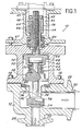
- the isolation device 10 shown in FIG. 1 comprises a housing in several parts 12, 14 and 16.
- the first part 12 of the housing is provided for being inserted in a pipe (not shown) upstream of a safety valve (not shown) to protect.
- the part 12 comprises a passage defined by a fluid inlet orifice 20 and by a fluid outlet orifice 22, the orifice 22 being of larger diameter and arranged at right angles to the orifice. 20, so that the latter opens into the orifice 22 by forming a valve seat 24 on the periphery.
- the part 12 of the housing is provided with flanges 26 and 28 arranged around the orifices 20 and 22 in order to allow the connection of this part 12 to the adjacent parts of the circuit.
- the part 14 of the housing is fixed to the part 12 by tie rods 18 and centered on the latter by a recess, so that the axis of a bore 30 formed in the part 14 is aligned with the axis of the inlet port 20.
- a disc 32 is slidably received inside bore 30 and has a projecting part 34 which extends through an opening 36 formed in part 12 of the housing to support at its end a valve 38 disposed opposite the valve seat 24.
- a washer 40 pinched between the parts 12 and 14 of the housing supports one end of a sealing bellows 42 disposed around the projecting part 34 and the other end of which is fixed to the valve 38.
- the disc 32 On the side opposite to the projecting part 34, the disc 32 carries a T-shaped part 44, the end of which is received in a housing 46 formed in a second disc 48 also slidingly mounted inside the bore 30. The end of the T-shaped part 44 is held inside the housing 46 by a flange 50 of the disc 48.
- elastic means are arranged between the discs 32 and 48 and , more precisely, between the disc 32 and the flange 50 in order to urge the discs away from one another.
- These elastic means consist of a stack of elastic washers 52.
- the Belleville washers 52 could be replaced by any equivalent system such as a helical spring.
- the disk 48 is integral with a rod 54 which extends away from the disk 32 through a portion of reduced diameter of the bore 30.
- the rod 54 and the disk 48 are immobilized in rotation by a key 56 received in a suitable keyway formed in part 14 of the housing.
- the rod 54 is threaded and receives a nut 58 mounted rotating inside the parts 14 and 16 of the housing and immobilized in translation between these parts by ball bearings 60.
- the part 16 of the housing is secured to the part 14 by means of tie rods 61 and centered on the part 14 by a recess, so that the axis of a bore 63 formed in the part 16 is aligned with the axis of the bore 30 and with the axis of the orifice d 'entry 20.
- the bore 63 receives the free end of the threaded rod 54 and part of the nut 58 on which is mounted a drive sleeve 64 secured in rotation to the nut 58 by means of a key 66 fixed to the 'nut and received in a suitable keyway formed in the sleeve 64.
- the portion 16 of the housing defines at its upper end a flange provided to support a drive motor (not shown) whose output shaft 65 rotates the sleeve 64 by means of a dog clutch system 62. It is understood that the rotation of the sleeve 64 causes the rotation of the nut 58 thanks to the key 66.
- the motor (not shown) can be controlled either automatically or manually in order to drive in rotation via the clutch system 62 the sleeve 24 and nut 58.
- the corresponding rotation of nut 58 has the consequence of controlling the downward movement by considering fig. 1 of the assembly constituted by the rod 54 and by the disc 48.
- the head of the T-shaped part 44 remains in contact with the washer 50 until the valve 38 comes into sealing contact against the valve seat 24.
- the displacement of the rod 54 and of the disc 48 then continues slightly, in order to guarantee the effectiveness of the sealing of the contact between the valve 38 and its seat 24.
- the closure of the inlet orifice 20 by the valve 38 results from the action of the setting means that constitute the Belleville washers 52.
- the respective dimensioning of the housing 46 formed in the disc 48 and of the head of the T-shaped part 44 received in this housing defines between the two movable members that constitute the discs 32 and 48 a connection with clearance which allows the valve 38 to move away from its seat 24 against the force exerted by the Belleville washers 52 when the pressure in the circuit upstream of the isolation device 10 is greater than a predetermined value by the calibration of the elastic washers.
- the isolation device according to the invention makes it possible to intervene automatically or manually in the event of blockage in the open position of the safety valve disposed downstream on the pipe without the circuit protection against deletions is not removed.
- the setting of the Belleville washers can be designed so as to ensure the opening of the valve constituted by the valve 38 and the seat 24 for a pressure equal to the opening pressure of the safety valve protected by the device 10 It will be noted that the escape of the fluid in the event of overpressure upstream of the device 10 is effected by the safety valve disposed downstream, which is then assumed to be in the open position.
- the isolation device shown in fig. 2 is identical to the isolation device which has just been described with reference to FIG. 1 but also comprises a hydraulic damper making it possible to damp the flaps of the valve when the latter has been brought into leaktight contact with its seat as a result of a failure of the safety valve disposed downstream and is urged away from this seat under the effect of an increase in the upstream pressure exceeding the setting pressure exerted by the elastic washers.
- the discs 32 and 48 constitute pistons which each carry an annular seal 68 which cooperates with the bore 30 so as to define a sealed chamber 70 filled with a hydraulic fluid such as jack oil.
- the chamber 70 communicates through passages 72 with an annular chamber 74 disposed above the chamber 70 and inside the part 14 of the housing.
- the chamber 74 is closed at its upper part by a plate 76 in which are formed vents 78 which communicate with the atmosphere.
- the lower part of the tank 74 is filled with oil as well as the passages 72 which open into the bottom of the tank, while the upper part of the tank 74 is filled with air and communicates with the atmosphere through the vents 789.
- the lower third of the reservoir 74 can be filled with cylinder oil and have a free surface in contact with the air contained in the upper part.
- diaphragms 80 are arranged in the passages 72 in order to limit the speed of flow of the oil between the chambers 70 and 74.
- the device which has just been described with reference to FIG. 2 constitutes a hydraulic damper which makes it possible to eliminate the phenomena of flapping of the valve 38 in the event of overpressure upstream of the isolation device 10 and after actuation of this device resulting from a failure of the safety valve (not shown) arranged in downstream.
- This phenomenon of beatings occurs when the pressure upstream of a safety valve returns contienently above the triggering threshold of this valve as soon as it closes.
- the device of fig. 2 dampens the displacements of the valve 38 and thus makes it possible to eliminate or at least attenuate these fluttering phenomena.
- This damping is obtained by the diaphragms 80 which prevent the piston 32 and the valve 38 which is associated with it from moving too quickly inside the bore 30 by limiting the speed of passage of the oil between the chamber 70 and chamber 74.
- the pressure upstream of the device 10 rises enough to urge the valve 38 away from its seat 24 against the force exerted by the Belleville washers 52 after a setting in operation of the device 10 by means of the motor (not shown)
- the displacement of the piston 32 which results therefrom causes part of the oil contained in the chamber 70 to pass into the chamber 74 through the passages 72.
- the embodiment of fig. 3 constitutes a variant of the embodiment of FIG. 2, in which the Belleville washers 52 ensuring the calibration of the valve 38 when the latter closes the valve seat 24 are replaced by pressurization of the oil contained in the chambers 70 and 74 fulfilling the same function.
- the annular chamber 74 communicates through the plate 76 with a pipe 82 fitted with a filling valve 84.
- the chamber 74 is completely sealed when the valve 84 is closed.
- the piping 82 communicates with a source of compressed neutral gas (not shown), so that the upper part of the chamber 74 is filled, for example up to half the total volume of this chamber, with neutral gas under pressure at by means of valve 84 which is then closed.
- This pressurized gas is in contact with the free surface of the oil contained in the chamber 74, so that it thus leaves the oil contained in the chamber 70 in order to exert a predetermined setting pressure on the piston 32.
- the pressure of the gas introduced into the upper part of the chamber 74 thus defines the triggering threshold of the safety valve constituted by the valve 38 and its seat 24 when this valve is closed following an activation in operation of the motor (not shown) following a blockage of the safety valve disposed downstream in the open position.
- diaphragms 80 arranged in the passages 72 through which the chamber 74 communicates with the chamber 70 make it possible to ensure damping of the flaps of the valve 38.
- the seals 68 associated with the pistons 32 and 48 can optionally be replaced by a bellows.
- the embodiments of FIGS. 2 and 3 have the essential advantage of allowing the circuit to be closed despite a blockage in the open position of a safety valve disposed downstream while continuing to protect this circuit against overpressure.
Landscapes
- Engineering & Computer Science (AREA)
- General Engineering & Computer Science (AREA)
- Mechanical Engineering (AREA)
- Safety Valves (AREA)
- Control Of Fluid Pressure (AREA)
- Details Of Valves (AREA)
- Fluid-Damping Devices (AREA)
Applications Claiming Priority (2)
| Application Number | Priority Date | Filing Date | Title |
|---|---|---|---|
| FR8007459 | 1980-04-02 | ||
| FR8007459A FR2479942A1 (fr) | 1980-04-02 | 1980-04-02 | Dispositif d'isolement a soupape de surete taree |
Publications (2)
| Publication Number | Publication Date |
|---|---|
| EP0037334A1 EP0037334A1 (fr) | 1981-10-07 |
| EP0037334B1 true EP0037334B1 (fr) | 1984-09-12 |
Family
ID=9240467
Family Applications (1)
| Application Number | Title | Priority Date | Filing Date |
|---|---|---|---|
| EP81400489A Expired EP0037334B1 (fr) | 1980-04-02 | 1981-03-27 | Dispositif à vanne d'isolement à protection contre surpressions |
Country Status (9)
| Country | Link |
|---|---|
| US (1) | US4364541A (enExample) |
| EP (1) | EP0037334B1 (enExample) |
| AR (1) | AR226350A1 (enExample) |
| BR (1) | BR8101941A (enExample) |
| CA (1) | CA1188956A (enExample) |
| DE (1) | DE3165928D1 (enExample) |
| ES (1) | ES8202119A1 (enExample) |
| FR (1) | FR2479942A1 (enExample) |
| ZA (1) | ZA811830B (enExample) |
Families Citing this family (19)
| Publication number | Priority date | Publication date | Assignee | Title |
|---|---|---|---|---|
| DE3132396C2 (de) * | 1981-08-17 | 1985-11-07 | Schultz, Wolfgang E., Dipl.-Ing., 8940 Memmingen | Elektromagnet |
| EP0116855B1 (en) * | 1983-01-21 | 1990-03-21 | Fujikin International, Inc. | Control valve |
| DE3715562C2 (de) * | 1987-05-09 | 1996-11-07 | Sempell Babcock Ag | Dämpfungseinrichtung für lineare Bewegungen |
| FR2621094B3 (fr) * | 1987-09-30 | 1989-12-29 | Beauvir Jacques | Vanne a commande manuelle |
| DE3901702A1 (de) * | 1989-01-21 | 1990-07-26 | Klein Schanzlin & Becker Ag | Lagereinrichtung fuer die gewindebuchse einer armaturenspindel |
| US5037277A (en) * | 1989-07-26 | 1991-08-06 | Flow International Corporation | Poppet valve for a high pressure fluid pump |
| DE19754257A1 (de) * | 1997-12-06 | 1999-06-10 | Bosch Gmbh Robert | Magnetventil für eine flüssigkeitsgeregelte Heiz- und/oder Kühlanlage |
| US6929238B2 (en) | 2000-02-18 | 2005-08-16 | Ga Industries Inc. | Electric motor actuated stop and self-closing check valve |
| DE10160970A1 (de) | 2001-12-11 | 2003-06-18 | Bosch Gmbh Robert | Ventil mit Dämfungselement |
| GB0221554D0 (en) * | 2002-09-17 | 2002-10-23 | Boc Group Plc | Cylinder valve |
| DE10321154A1 (de) | 2003-05-12 | 2004-12-02 | Robert Bosch Gmbh | Ventil |
| US7694939B2 (en) * | 2005-09-01 | 2010-04-13 | Smc Kabushiki Kaisha | Flow rate control valve |
| US8408518B2 (en) * | 2009-11-13 | 2013-04-02 | Fisher Controls International, Llc | Electric actuators having internal load apparatus |
| US8636262B2 (en) * | 2009-11-13 | 2014-01-28 | Fisher Controls International, Llc | Coupling apparatus for use with electric actuators |
| US8979063B2 (en) | 2011-11-28 | 2015-03-17 | Fisher Controls International Llc | Failsafe apparatus for use with linear actuators |
| US9151401B2 (en) * | 2011-12-29 | 2015-10-06 | Tescom Corporation | Fail-safe apparatus for use with fluid valves |
| JP6295499B2 (ja) | 2012-07-18 | 2018-03-20 | プレス−ヴァク エンジニアリング アーペーエス | 圧力解放バルブ |
| US9958083B1 (en) * | 2016-10-27 | 2018-05-01 | National Enviornmental Products, Ltd. | Force limited valve actuator and method therefor |
| CN111637260B (zh) * | 2020-06-10 | 2021-11-09 | 盐城支点机械制造有限公司 | 一种方便更换滤网的阀门 |
Citations (3)
| Publication number | Priority date | Publication date | Assignee | Title |
|---|---|---|---|---|
| US1146723A (en) * | 1914-07-03 | 1915-07-13 | Perry Losh | Combined stop and relief valve. |
| DE2430725A1 (de) * | 1974-06-26 | 1976-01-15 | Kraftwerk Union Ag | Druckwasserreaktoranlage |
| GB1455180A (en) * | 1973-09-10 | 1976-11-10 | Kraftwerk Union Ag | Nuclear reactor installation |
Family Cites Families (10)
| Publication number | Priority date | Publication date | Assignee | Title |
|---|---|---|---|---|
| US1427111A (en) * | 1918-01-28 | 1922-08-29 | Hans L Knudsen | Valve mechanism |
| DE426893C (de) * | 1922-08-24 | 1926-03-19 | Ludwig Poldermann | Auslassventil fuer Vulkanisierapparate und aehnliche Dampfverbraucher |
| US1582938A (en) * | 1923-09-12 | 1926-05-04 | Henry M Smith | Valve |
| US1541757A (en) * | 1924-03-05 | 1925-06-09 | Ohio Injector Company | Valve |
| FR1304153A (fr) * | 1961-08-10 | 1962-09-21 | Air Liquide | Perfectionnements aux dispositifs commandant un clapet |
| US3198034A (en) * | 1961-11-17 | 1965-08-03 | Stamicarbon | Valve actuator |
| US3589671A (en) * | 1969-10-21 | 1971-06-29 | Gerdts Gustav F Kg | Valve |
| US3702142A (en) * | 1970-07-27 | 1972-11-07 | Dresser Ind | Safety valve having back pressure compensator |
| US3850405A (en) * | 1973-07-05 | 1974-11-26 | Chandler Evans Inc | Contaminant resistant valve |
| US4062375A (en) * | 1976-06-18 | 1977-12-13 | Center Compression Lock Company | Tamper proof lock |
-
1980
- 1980-04-02 FR FR8007459A patent/FR2479942A1/fr active Granted
- 1980-07-01 US US06/164,908 patent/US4364541A/en not_active Expired - Lifetime
-
1981
- 1981-03-19 ZA ZA00811830A patent/ZA811830B/xx unknown
- 1981-03-27 EP EP81400489A patent/EP0037334B1/fr not_active Expired
- 1981-03-27 DE DE8181400489T patent/DE3165928D1/de not_active Expired
- 1981-03-31 CA CA000374290A patent/CA1188956A/en not_active Expired
- 1981-03-31 BR BR8101941A patent/BR8101941A/pt unknown
- 1981-04-01 ES ES500984A patent/ES8202119A1/es not_active Expired
- 1981-04-02 AR AR284849A patent/AR226350A1/es active
Patent Citations (3)
| Publication number | Priority date | Publication date | Assignee | Title |
|---|---|---|---|---|
| US1146723A (en) * | 1914-07-03 | 1915-07-13 | Perry Losh | Combined stop and relief valve. |
| GB1455180A (en) * | 1973-09-10 | 1976-11-10 | Kraftwerk Union Ag | Nuclear reactor installation |
| DE2430725A1 (de) * | 1974-06-26 | 1976-01-15 | Kraftwerk Union Ag | Druckwasserreaktoranlage |
Also Published As
| Publication number | Publication date |
|---|---|
| BR8101941A (pt) | 1981-10-06 |
| ES500984A0 (es) | 1982-01-01 |
| AR226350A1 (es) | 1982-06-30 |
| CA1188956A (en) | 1985-06-18 |
| ES8202119A1 (es) | 1982-01-01 |
| FR2479942B1 (enExample) | 1982-07-16 |
| US4364541A (en) | 1982-12-21 |
| ZA811830B (en) | 1982-04-28 |
| EP0037334A1 (fr) | 1981-10-07 |
| FR2479942A1 (fr) | 1981-10-09 |
| DE3165928D1 (en) | 1984-10-18 |
Similar Documents
| Publication | Publication Date | Title |
|---|---|---|
| EP0037334B1 (fr) | Dispositif à vanne d'isolement à protection contre surpressions | |
| EP0303735B1 (fr) | Appareil détendeur perfectionné | |
| FR2567615A1 (fr) | Soupape de modulation pilotee a commande par pression | |
| FR2569440A1 (fr) | Soupape de surete pour puits | |
| CA2270579A1 (fr) | Dispositif de maintien en position de la tige d'un verin hydraulique | |
| EP0032346A1 (fr) | Soupape de sûreté équipée d'un frein hydraulique | |
| FR2600744A1 (fr) | Robinet d'arret et de commande d'ecoulement | |
| FR2509831A1 (fr) | Commande de remise en position pour soutenement a etancons hydrauliques, ainsi qu'une vanne de non-retour a commande hydraulique | |
| FR2496823A1 (fr) | Valve de chargement pour frein de vehicule ferroviaire | |
| EP0237456B1 (fr) | Amortisseur hydraulique de battements et son application aux soupapes et analogues | |
| FR2550607A1 (fr) | Regulateur destine a etre monte sur le raccord de sortie d'une bouteille de gaz ou recipient analogue | |
| EP0227541B1 (fr) | Soupape de sûreté à pilotage intégré | |
| FR2511467A1 (fr) | Valve de commande | |
| EP0428433B1 (fr) | Dispositif de calage de la plaque supérieure de support des guides de grappes par rapport à la cuve d'un réacteur nucléaire | |
| FR2524960A1 (fr) | Dispositif autonome d'assistance d'une soupape de securite | |
| EP1869534A1 (fr) | Ensemble valve régulé pour systèmes d'extincteurs d'incendie | |
| FR2538493A1 (fr) | Soupape de surete a pilotage integre | |
| EP0743489B1 (fr) | Installation d'alimentation en gaz, équipement de mise en oeuvre d'une flamme la comportant, et détendeur correspondant | |
| EP0027227B1 (fr) | Soupape de décharge pour installation hydraulique | |
| WO1995013973A1 (fr) | Procede de commande d'un dispositif de distribution pour l'alimentation d'une capacite avec un fluide gazeux, moyens pour la mise en ×uvre de ce procede et dispositif equipe de ces moyens | |
| BE521782A (fr) | Régulateur hydraulique de pression de gaz | |
| EP0260166B1 (fr) | Dispositif de bouteille formant récipient de gaz sous pression | |
| FR2715142A1 (fr) | Dispositif de sécurité et de vidange pour citerne ou conteneur de produits liquides. | |
| WO1990002899A1 (fr) | Vanne haute pression utilisable notamment dans un outil de coupe a jet fluide | |
| FR2666992A1 (fr) | Dispositif de securite pour bac de stockage de produits inflammables. |
Legal Events
| Date | Code | Title | Description |
|---|---|---|---|
| PUAI | Public reference made under article 153(3) epc to a published international application that has entered the european phase |
Free format text: ORIGINAL CODE: 0009012 |
|
| AK | Designated contracting states |
Designated state(s): BE DE GB IT SE |
|
| 17P | Request for examination filed |
Effective date: 19820306 |
|
| ITF | It: translation for a ep patent filed | ||
| GRAA | (expected) grant |
Free format text: ORIGINAL CODE: 0009210 |
|
| AK | Designated contracting states |
Designated state(s): BE DE GB IT SE |
|
| REF | Corresponds to: |
Ref document number: 3165928 Country of ref document: DE Date of ref document: 19841018 |
|
| PLBE | No opposition filed within time limit |
Free format text: ORIGINAL CODE: 0009261 |
|
| STAA | Information on the status of an ep patent application or granted ep patent |
Free format text: STATUS: NO OPPOSITION FILED WITHIN TIME LIMIT |
|
| 26N | No opposition filed | ||
| PGFP | Annual fee paid to national office [announced via postgrant information from national office to epo] |
Ref country code: SE Payment date: 19910227 Year of fee payment: 11 |
|
| PGFP | Annual fee paid to national office [announced via postgrant information from national office to epo] |
Ref country code: DE Payment date: 19910308 Year of fee payment: 11 |
|
| PGFP | Annual fee paid to national office [announced via postgrant information from national office to epo] |
Ref country code: BE Payment date: 19910314 Year of fee payment: 11 |
|
| PGFP | Annual fee paid to national office [announced via postgrant information from national office to epo] |
Ref country code: GB Payment date: 19910319 Year of fee payment: 11 |
|
| ITTA | It: last paid annual fee | ||
| PG25 | Lapsed in a contracting state [announced via postgrant information from national office to epo] |
Ref country code: GB Effective date: 19920327 |
|
| PG25 | Lapsed in a contracting state [announced via postgrant information from national office to epo] |
Ref country code: SE Effective date: 19920328 |
|
| PG25 | Lapsed in a contracting state [announced via postgrant information from national office to epo] |
Ref country code: BE Effective date: 19920331 |
|
| BERE | Be: lapsed |
Owner name: SOC. D'EXPLOITATION DE BREVETS POUR L'INDUSTRIE ET Effective date: 19920331 Owner name: ELECTRICITE DE FRANCE SERVICE NATIONAL Effective date: 19920331 |
|
| GBPC | Gb: european patent ceased through non-payment of renewal fee | ||
| PG25 | Lapsed in a contracting state [announced via postgrant information from national office to epo] |
Ref country code: DE Effective date: 19921201 |
|
| EUG | Se: european patent has lapsed |
Ref document number: 81400489.1 Effective date: 19921005 |