EP0037307A1 - Système de régulation de vitesse pour moteur asynchrone à double stator - Google Patents
Système de régulation de vitesse pour moteur asynchrone à double stator Download PDFInfo
- Publication number
- EP0037307A1 EP0037307A1 EP81400406A EP81400406A EP0037307A1 EP 0037307 A1 EP0037307 A1 EP 0037307A1 EP 81400406 A EP81400406 A EP 81400406A EP 81400406 A EP81400406 A EP 81400406A EP 0037307 A1 EP0037307 A1 EP 0037307A1
- Authority
- EP
- European Patent Office
- Prior art keywords
- stator
- regulation
- group
- phase
- supply
- Prior art date
- Legal status (The legal status is an assumption and is not a legal conclusion. Google has not performed a legal analysis and makes no representation as to the accuracy of the status listed.)
- Withdrawn
Links
- 230000006698 induction Effects 0.000 title 1
- 239000004065 semiconductor Substances 0.000 claims abstract description 14
- 230000033228 biological regulation Effects 0.000 claims description 37
- 230000004907 flux Effects 0.000 claims description 14
- 238000004804 winding Methods 0.000 claims description 14
- 230000001105 regulatory effect Effects 0.000 claims description 8
- 230000000737 periodic effect Effects 0.000 claims 1
- 238000000034 method Methods 0.000 description 7
- 239000013598 vector Substances 0.000 description 6
- 238000010586 diagram Methods 0.000 description 5
- 239000003990 capacitor Substances 0.000 description 2
- 238000010276 construction Methods 0.000 description 2
- 239000004020 conductor Substances 0.000 description 1
- 230000007423 decrease Effects 0.000 description 1
- 230000000694 effects Effects 0.000 description 1
- 238000005516 engineering process Methods 0.000 description 1
- 230000010363 phase shift Effects 0.000 description 1
- 230000033764 rhythmic process Effects 0.000 description 1
Images
Classifications
-
- H—ELECTRICITY
- H02—GENERATION; CONVERSION OR DISTRIBUTION OF ELECTRIC POWER
- H02K—DYNAMO-ELECTRIC MACHINES
- H02K17/00—Asynchronous induction motors; Asynchronous induction generators
- H02K17/02—Asynchronous induction motors
- H02K17/34—Cascade arrangement of an asynchronous motor with another dynamo-electric motor or converter
- H02K17/36—Cascade arrangement of an asynchronous motor with another dynamo-electric motor or converter with another asynchronous induction motor
-
- H—ELECTRICITY
- H02—GENERATION; CONVERSION OR DISTRIBUTION OF ELECTRIC POWER
- H02P—CONTROL OR REGULATION OF ELECTRIC MOTORS, ELECTRIC GENERATORS OR DYNAMO-ELECTRIC CONVERTERS; CONTROLLING TRANSFORMERS, REACTORS OR CHOKE COILS
- H02P5/00—Arrangements specially adapted for regulating or controlling the speed or torque of two or more electric motors
- H02P5/74—Arrangements specially adapted for regulating or controlling the speed or torque of two or more electric motors controlling two or more AC dynamo-electric motors
Definitions
- the invention relates to a speed variation system for an asynchronous motor of a special construction.
- the speed variation of conventional asynchronous motors can be obtained in different ways. The most effective consists in the simultaneous variation of the frequency and the stator voltage. However, electronic control is very expensive, which limits the dissemination of this method. You can also vary the stator voltage. The method is very limited due to poor performance. The regulation range is very small and the torque decreases quickly. For motors with wound rotors, there is also a method for varying the speed by means of rotor current regulation. The scope of the method is also limited.
- a regulation system for a single or multi-phase asynchronous motor comprising two independent stators of which at least one, called supply stator, is connected to the AC network and supplied with constant voltage, and a rotor formed by two half-rotors which are electrically and mechanically coupled to each other and which are respectively magnetically coupled to one of the stators, the other stator said regulation being connected to a circuit comprising at least one current regulation member, while the two half-rotors carry a single electrical winding, preferably with a cage.
- the speed variation is obtained thanks to impedances of various natures, such as variable inductances, resistances of regulation and transformers. These elements are expensive and bulky.
- the invention therefore aims to provide a regulation system of the type defined above for an asynchronous motor with double stator and rotor in which the aforementioned drawbacks are avoided.
- said circuit comprises a first group of controlled semiconductor switches intended to supply each phase of said regulation stator in a first direction as well as a second group of controlled semiconductor switches intended to supply, in alternation with the first group, each phase of the regulation stator in the opposite direction, a control circuit to cause the selective triggering for predefined - ended durations of each of the switches of each group, and in that the coils of the phases of said regulating stator are connected together so that the resulting magnetic flux is in phase with the flux of the supply stator when the first group of switches conducts and in phase opposition when the other group of switches conducts .
- the motor therefore receives on its regulation stator a variable voltage generated by the sequential control of the semiconductor switches.
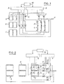
- Figs. 1 and 2 are two different diagrams of a regulation system for an asynchronous motor with double rotor, according to the invention
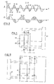
- Fig. 3 shows curves of different operating cycles of the system shown in FIG. 2;
- Figs 4 and 5 are simplified diagrams showing other characteristics of the regulation system according to the invention.
- the motor used with the regulation system according to the invention comprises two so-called supply and regulation stators, respectively.
- the rotor is made up of two half-rotors.
- the stacking lengths of the magnetic circuit of the half-rotors correspond to the stacking lengths of the stators, respectively.
- Conductors pass through the two half-rotors and are short-circuited by two rings placed at each end of the rotor.
- the coil heads must have the smallest possible dimensions, in particular between the two stators.
- the motor can be single or multi-phase.
- the stators are preferably positioned so that the flux vectors of each stator are in phase. Generally, this will be achieved by aligning the corresponding windings of each stator and a suitable connection.
- the two stators have the same number of poles.
- the construction technology is classic.
- Fig. 1 schematically shows a first embodiment of the regulation system according to the invention.
- the stator 1 is supplied with constant voltage from the sector S.
- the stator 2 is supplied with variable voltage by an autotransformer 3, 4.
- Part 3 of the autotransformer supplies the stator 2 with phase voltage, that is to say -to say the flux vector is in phase with the flux vector of the stator 1.
- Part 4 of the autotransformer supplies the stator 2 in phase opposition.
- the device 3, 4 instead of an autotransformer can be a continuously variable or stepwise transformer.
- Each winding of the autotransformer 3, 4 is connected by an adjustable cursor socket to a semiconductor switch divided into two groups 5 and 6 connected in turn to the free ends of the windings 7 of the control stator 2.
- the opposite ends of these windings are here connected together.
- the semiconductor switches 5 and 6 allow the very rapid change of the direction of supply of the phases of the regulation stator winding and, if necessary, the rapid change of the taps, so that the resulting magnetic flux is in phase with the flow of the supply stator 1 when the first group of switches is conducting and in phase opposition when the other group of switches is conducting.
- the groups of switches 5 and 6 are controlled by their control electrode, which are connected to two circuits 8 and 9 for distributing the trigger to which is connected a rhythm circuit 10 which determines the succession of the instants of triggering according to a predetermined or controlled program.
- the switches can be thyristors, transistors or triacs.
- Fig. 2 schematically shows another embodiment of the regulation system.
- the stator 1 is supplied by a constant voltage.
- the stator 2 is supplied by semiconductor contactors which can also be transistors, thyristors or triacs.
- the other group 13, 14 behaves like an open switch.
- the control electrodes are connected in the same way as in FIG. l, so as to ensure alternately the conduction of one or the other group according to the frequency and the programmed duration of conduction.
- the conduction time of one group can be zero, while that of the other is 100%.
- Curve A schematically shows the possibilities of operation with thyristors. It will be assumed that a group 11, 12 for example, supplies the motor in phase, while the other group 13, 14 supplies it in phase opposition.
- the conduction periods of group 11, 12 are indicated by dots, the conduction periods of group 13, 14 are hatched.
- the control can be carried out by entire periods, or by varying the angle of conduction, or in a mixed manner.
- Curve B in Fig. 3 shows the additional possibilities offered by the power transistors allowing both the opening and the closing of the switch during the considered alternation of the sector.
- the control must determine the conduction times so as to eliminate the DC component of the current.
- capacitors working during periods of phase opposition conduction can be connected to the stator 2 terminals. They reduce the phase shift of the current and improve the performance of the motor.
- the F ⁇ g. 4 shows the most general case of regulation.
- the winding 15 represents a phase of the regulating stator of a double stator motor.
- the number of phases can be any.
- the constant voltage supply stator is not shown here. It has the same number of phases as the regulation stator.
- the diagram includes three groups 16, 17 and 18 of semiconductor switches, such as transistors or thyristors. If one of the groups conducts the current, the other groups behave like open switches. It will be assumed that the group 16 conducts the current and that the flux vector of the regulating stator is in phase with the flux vector of the supply stator.
- the electromotive force generated by the regulating stator contributes to supplying energy to the rotor and contributes to generating the rotor torque. If group 16 stops driving and group 17 becomes conductive, the flow vector of the regulation stator will be 180 ° out of phase with respect to the supply stator. The electromotive force generated will also be 180 ° out of phase with that induced by the supply stator. Its average value will be regulated by the duration of the group's conduction.
- the electromotive force being in phase opposition, the part of the machine comprising the regulation stator behaves like an asynchronous generator restoring active power to the network. This main electromotive force induced by the supply stator, behaves like a variable rotor resistance.
- Another group of switches 18 makes it possible to short-circuit the regulation stator (operation in passive mode), possibly on an impedance.
- this impedance is represented by a group 19 of capacitors.
- Group 18, 19 is an additional possibility which can be chosen to modify the operating characteristics. The desired characteristics are obtained by regulating the operating times of each group 16, 17, 18 of the switches.
- the control of the elements 16, 17, 18 can be ensured by a control circuit 20 similar to the circuits 8; 9 and 10 of the previous Figures.
- the command can be carried out to produce any desired sequences according to known rules and techniques.
- each phase of the regulation stator will be subjected to the same process: an alternating phase supply with a supply in phase opposition and, possibly, with a short-circuit of the windings on themselves with or without external impedance.
- the essence of the system consists in determining the direction and, if necessary, the amplitude of the flux resulting from one stator relative to the other.
- the desired effect can be obtained by intervention on a part of the supply stator or even on a part of the regulating stator as shown in FIG. 5.
- the amplitude of the flux can be modified by the power supply by means of one or more taps on the windings comprising a variable number of turns.
- This method can replace transformer operation as explained in connection with FIG. l.
- the asynchronous motor with its speed variation system can be applied for industrial variable speed drive devices for example.
Landscapes
- Engineering & Computer Science (AREA)
- Power Engineering (AREA)
- Control Of Ac Motors In General (AREA)
Applications Claiming Priority (2)
| Application Number | Priority Date | Filing Date | Title |
|---|---|---|---|
| FR8006477A FR2478899A1 (fr) | 1980-03-24 | 1980-03-24 | Systeme de regulation de vitesse pour moteur asynchrone |
| FR8006477 | 1980-03-24 |
Publications (1)
| Publication Number | Publication Date |
|---|---|
| EP0037307A1 true EP0037307A1 (fr) | 1981-10-07 |
Family
ID=9240004
Family Applications (1)
| Application Number | Title | Priority Date | Filing Date |
|---|---|---|---|
| EP81400406A Withdrawn EP0037307A1 (fr) | 1980-03-24 | 1981-03-17 | Système de régulation de vitesse pour moteur asynchrone à double stator |
Country Status (3)
| Country | Link |
|---|---|
| EP (1) | EP0037307A1 (enExample) |
| JP (1) | JPS5720196A (enExample) |
| FR (1) | FR2478899A1 (enExample) |
Cited By (1)
| Publication number | Priority date | Publication date | Assignee | Title |
|---|---|---|---|---|
| EP0093615A1 (en) * | 1982-05-03 | 1983-11-09 | The Garrett Corporation | Variable speed rotary electrical machines |
Citations (5)
| Publication number | Priority date | Publication date | Assignee | Title |
|---|---|---|---|---|
| DE871481C (de) * | 1951-08-03 | 1953-03-23 | Siemens Ag | Asynchronmotor, insbesondere fuer den Antrieb von Gesteinsdrehbohrmaschinen |
| FR1142902A (fr) * | 1952-01-03 | 1957-09-24 | Siemens Ag | Moteurs asynchrones couplés en cascade |
| NL6709715A (enExample) * | 1967-07-12 | 1969-01-14 | ||
| FR2200660A1 (enExample) * | 1972-09-19 | 1974-04-19 | Occhetto Sergio | |
| AT338384B (de) * | 1975-10-14 | 1977-08-25 | Elin Union Ag | Induktionsmaschinenkaskade |
-
1980
- 1980-03-24 FR FR8006477A patent/FR2478899A1/fr active Granted
-
1981
- 1981-03-17 EP EP81400406A patent/EP0037307A1/fr not_active Withdrawn
- 1981-03-23 JP JP4224281A patent/JPS5720196A/ja active Pending
Patent Citations (5)
| Publication number | Priority date | Publication date | Assignee | Title |
|---|---|---|---|---|
| DE871481C (de) * | 1951-08-03 | 1953-03-23 | Siemens Ag | Asynchronmotor, insbesondere fuer den Antrieb von Gesteinsdrehbohrmaschinen |
| FR1142902A (fr) * | 1952-01-03 | 1957-09-24 | Siemens Ag | Moteurs asynchrones couplés en cascade |
| NL6709715A (enExample) * | 1967-07-12 | 1969-01-14 | ||
| FR2200660A1 (enExample) * | 1972-09-19 | 1974-04-19 | Occhetto Sergio | |
| AT338384B (de) * | 1975-10-14 | 1977-08-25 | Elin Union Ag | Induktionsmaschinenkaskade |
Cited By (1)
| Publication number | Priority date | Publication date | Assignee | Title |
|---|---|---|---|---|
| EP0093615A1 (en) * | 1982-05-03 | 1983-11-09 | The Garrett Corporation | Variable speed rotary electrical machines |
Also Published As
| Publication number | Publication date |
|---|---|
| JPS5720196A (en) | 1982-02-02 |
| FR2478899B1 (enExample) | 1983-07-08 |
| FR2478899A1 (fr) | 1981-09-25 |
Similar Documents
| Publication | Publication Date | Title |
|---|---|---|
| US6831430B2 (en) | High phase order motor with mesh connected windings | |
| FR2557393A1 (fr) | Moteur a courant continu a reluctance a une ou plusieurs phases | |
| FR2615016A1 (fr) | Dispositif de source d'alimentation a commutation | |
| WO2010067021A2 (fr) | Dispositif à machine électrique polyphasée et machine électrique associée | |
| FR2496521A1 (fr) | Appareil de soudage electrique et procede d'obtention d'une source de courant de soudage | |
| FR2814006A1 (fr) | Dispositif de conversion d'energie electrique a decoupage | |
| EP0095398A1 (fr) | Tranformateur électrique à circuits primaires modulaires alimentés sélectivement | |
| US6479959B2 (en) | Self-excited reluctance motor | |
| EP0037307A1 (fr) | Système de régulation de vitesse pour moteur asynchrone à double stator | |
| FR2566957A1 (fr) | Procede d'installation de bobines d'induction a noyau d'air | |
| FR2730878A1 (fr) | Dispositif de commande d'un moteur electrique a vitesse variable | |
| FR2512602A1 (fr) | Machines electriques tournantes a courant continu a poles de compensation auxiliaires | |
| US4382218A (en) | Speed control for fan motor | |
| EP0670628B1 (fr) | Dispositif d'alimentation pour moteur électrique à courant alternatif | |
| Emarloo et al. | Extended-Speed-Range Low-Torque-Ripple Control for Unsaturated Switched Reluctance Motors | |
| EP2695289A2 (fr) | Procédé de commande d'un onduleur de tension et dispositif associé | |
| SU867547A1 (ru) | Электромашинный сварочный генератор | |
| SU1552301A1 (ru) | Вентильный электродвигатель | |
| EP0320560A1 (fr) | Dispositif moteur pour l'alimentation de véhicules et engins industriels | |
| RU2044400C1 (ru) | Электропривод переменного тока | |
| FR2717013A1 (fr) | Dispositif de commutation hybride, onduleurs d'alimentation de moteurs électriques incluant ce dispositif et moteurs ainsi alimentés. | |
| JPS6152182A (ja) | 無整流子電動機の駆動装置 | |
| KR100350807B1 (ko) | 자기 여자형 릴럭턴스 모터 | |
| FR2735919A1 (fr) | Dispositif d'alimentation d'un moteur a reluctance variable | |
| SU1483562A1 (ru) | Коллекторный генератор переменного тока |
Legal Events
| Date | Code | Title | Description |
|---|---|---|---|
| PUAI | Public reference made under article 153(3) epc to a published international application that has entered the european phase |
Free format text: ORIGINAL CODE: 0009012 |
|
| AK | Designated contracting states |
Designated state(s): AT BE CH DE GB IT LU NL SE |
|
| STAA | Information on the status of an ep patent application or granted ep patent |
Free format text: STATUS: THE APPLICATION HAS BEEN WITHDRAWN |
|
| 18W | Application withdrawn |
Withdrawal date: 19820419 |
|
| RIN1 | Information on inventor provided before grant (corrected) |
Inventor name: SOBIEPANEK, JANUSZ |