EP0036632A2 - Trocknungssystem - Google Patents
Trocknungssystem Download PDFInfo
- Publication number
- EP0036632A2 EP0036632A2 EP81102032A EP81102032A EP0036632A2 EP 0036632 A2 EP0036632 A2 EP 0036632A2 EP 81102032 A EP81102032 A EP 81102032A EP 81102032 A EP81102032 A EP 81102032A EP 0036632 A2 EP0036632 A2 EP 0036632A2
- Authority
- EP
- European Patent Office
- Prior art keywords
- web
- electrodes
- liquid
- evaporation
- static electrical
- Prior art date
- Legal status (The legal status is an assumption and is not a legal conclusion. Google has not performed a legal analysis and makes no representation as to the accuracy of the status listed.)
- Withdrawn
Links
Images


Classifications
-
- F—MECHANICAL ENGINEERING; LIGHTING; HEATING; WEAPONS; BLASTING
- F26—DRYING
- F26B—DRYING SOLID MATERIALS OR OBJECTS BY REMOVING LIQUID THEREFROM
- F26B3/00—Drying solid materials or objects by processes involving the application of heat
-
- D—TEXTILES; PAPER
- D21—PAPER-MAKING; PRODUCTION OF CELLULOSE
- D21F—PAPER-MAKING MACHINES; METHODS OF PRODUCING PAPER THEREON
- D21F5/00—Dryer section of machines for making continuous webs of paper
-
- D—TEXTILES; PAPER
- D21—PAPER-MAKING; PRODUCTION OF CELLULOSE
- D21F—PAPER-MAKING MACHINES; METHODS OF PRODUCING PAPER THEREON
- D21F5/00—Dryer section of machines for making continuous webs of paper
- D21F5/16—Drying webs by electrical heating
-
- F—MECHANICAL ENGINEERING; LIGHTING; HEATING; WEAPONS; BLASTING
- F26—DRYING
- F26B—DRYING SOLID MATERIALS OR OBJECTS BY REMOVING LIQUID THEREFROM
- F26B13/00—Machines and apparatus for drying fabrics, fibres, yarns, or other materials in long lengths, with progressive movement
- F26B13/10—Arrangements for feeding, heating or supporting materials; Controlling movement, tension or position of materials
- F26B13/14—Rollers, drums, cylinders; Arrangement of drives, supports, bearings, cleaning
- F26B13/145—Rollers, drums, cylinders; Arrangement of drives, supports, bearings, cleaning on the non-perforated outside surface of which the material is being dried by convection or radiation
-
- F—MECHANICAL ENGINEERING; LIGHTING; HEATING; WEAPONS; BLASTING
- F26—DRYING
- F26B—DRYING SOLID MATERIALS OR OBJECTS BY REMOVING LIQUID THEREFROM
- F26B7/00—Drying solid materials or objects by processes using a combination of processes not covered by a single one of groups F26B3/00 and F26B5/00
- F26B7/002—Drying solid materials or objects by processes using a combination of processes not covered by a single one of groups F26B3/00 and F26B5/00 using an electric field and heat
Definitions
- the present invention relates to an improved drying apparatus. and method for removing volatile liquid from a liquid bearing web of material, which apparatus and method may find particular application in drying a wet moving web of paper or like material.
- a slurry of fibers and water in a head box is permitted to flow onto a support of woven wire material, known as a Fourdrinier wire belt which is moved beneath the head box at a uniform speed. Water drains through the Fourdrinier belt, thus leaving a thin layer of intermeshed fibers. Drainage of the water from the fibers may be assisted by suction boxes beneath the Fourdrinier belt.
- the resulting web may be transferred onto a felt belt for further drying. Water may also be removed from the web by feeding it between a series of press rollers and between felt covered rolls. The paper web may then pass around a series of steam heated iron cylinders such that these cylinders heat the paper web sufficiently to cause evaporation of the remaining moisture.
- a dryer felt web may also be guided around the heated dryer drum overlaying the paper web.
- the dryer felt web is maintained under tension so as to apply a uniform pressure against the paper web, thus improving the conduction of heat from the steam heated drum into the moisture bearing paper web. Since, under normal operating conditions, the dryer felt web is not intended to absorb water in liquid form, it is typically formed of a hard, generally non-absorbent fabric.
- U.S. Patent No. 3,771,233, issued November 13, 1973, to French et al discloses a method of applying a high voltage direct current discharge to a liquid or a solid mass containing. liquid, while the surface of the liquid or solid mass is in contact with a circulating gaseous atmosphere. Evaporation of the liquid is promoted by this technique due to turbulence of the atmosphere brought about by the discharge adjacent the surface of the liquid.
- the French et al disclosure is directed specifically to drying investment casting shell molds. The mold is placed in an oven for evaporation drying.
- the positive terminal of a high voltage d.c. power source is connected to the mold and to ground and a negative terminal of the power source is connected to a plurality of needlelike electrodes which surround but do not contact the mold.
- U.S. patents issued to Robert R. Candor and James T. Candor, relate to the use of a static electrical field to assist in removal of water in a liquid form from various types of material, including paper, by causing the water to migrate physically in the direction of the field out of the moisture bearing material.
- These patents include U.S. Patent Nos. 3,633,282, issued January 11, 1972; 3,543,408, issued December 1, 1970; 3,641,680, issued February 15, 1972; 3,755,911, issued September 4, 1973; 3,757,426, issued September 11, 1973; 3,931,682, issued January 13, 1976; 3,999,302, issued December 28, 1976; and 3,977,937, issued August 31, 1976.
- the paper drying devices disclosed in the Candor patents are generally of the type which subject the paper web to a field by placing oppositely charged electrodes on opposite sides of the web or, in the case of the embodiment of Fig. 7 of the Candor '426 patent, by electrically connecting one side of a high potential source to the slurry forming the wet web and .connecting the opposite side of the high potential source to a plurality of electrodes positioned beneath the web. It should be appreciated that an opposing electrode configuration may not be practicable in evaporation drying devices where heating apparatus must be positioned on one side of the paper web.
- the Candor patents further suggest the use of suction, as in Candor '426, to assist in the removal of liquid water, as well as the use of vibrational energy or soundwaves, as in the Candor '682 and '680 patents, in conjunction with the use of an electrostatic field for removal of the liquid water.
- the Candor '302 patent further suggests dielectric heating in conjunction with electrostatic and vibratory liquid water removal, while the '937 patent suggests the use of patterned conductive belts for supporting the paper web and rearranging the position of the web fibers.
- drum dryers in which a plurality of electrode pairs, each pair including electrodes differing substantially in area, are provided on opposite sides of a web of moist paper. Half of the electrodes are positioned within the drum which must therefore be non-metallic, so as not to shield the electrodes.
- a drying system for removing volatile liquid from a liquid bearing web of material by evaporation includes means for moving a liquid bearing web of material through a drying station.
- a heating means positioned at the drying station, applies evaporation energy to the liquid bearing web of material to effect evaporation of the liquid from the web.
- An electrostatic means subjects the web of material to a static electrical field at the drying station, thereby enhancing the evaporation of volatile liquid from the web.
- the heating means may comprise a rotatable heated cylindrical drum in contact with the liquid bearing web and belt means contacting the liquid bearing web and urging the web against the drum.
- the heating means may comprise a .source of radiant energy, including a plurality of infrared burners, positioned above the web at the drying station.
- the heating means may comprise means for directing heated air against the web at the drying station.
- the electrostatic means may comprise a plurality of electrodes positioned at the drying station and spaced apart along the web in the direction of web movement through the drying station.
- the electrostatic means further includes means for supplying static electrical potentials to selected ones of the plurality of electrodes.
- the electrodes may all be positioned on one side of the web with a first static electrical potential supplied to a number of the electrodes and a second static electrical potential supplied to others of the electrodes.
- the first static electrical potential may be supplied to alternate electrodes along the web of material, and the second static electrical potential may be supplied to electrodes positioned intermediate the alternate electrodes.
- the electrodes may be positioned circumferentially around the drum and outwardly from the web with each of the electrodes extending across the width of the web.
- the electrostatic means may further comprise frame means including a pair of nonconductive supports extending circumferentially around the drum, with the supports being spaced apart in a direction parallel to the axis of rotation of the drum by a distance at least as great as the width of the moisture bearing web.
- Each of the electrodes in such an arrangement comprises an electrode wire extending between the supports and connected to receive one of the first and second static electrical potentials.
- the frame means may further comprise means for tensioning the electrode wires across the supports.
- the electrostatic means may comprise a plurality of electrodes positioned beneath the web.
- Each electrode may comprise an elongated el-ectrode member extending across the width of the web, with each electrode member being connected to receive one of the first and second static electrical potentials.
- the electrodes may each comprise a sheet of electrically conductive material extending across the width of the web and providing a substantial electrode area.
- the method of removing volatile liquid from a liquid bearing web of material by evaporation comprises the steps of:
- the step of applying an evaporation energy to the liquid bearing web of material may include the step of heating the liquid bearing web by irradiating the web with infrared energy.
- this step may include the step of directing heated air against the liquid bearing web.
- the step of subjecting the liquid bearing web of material to a static electrical field may include the step of subjecting the liquid bearing web to a nonuniform static electrical field.
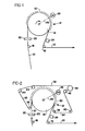
- Figs. 1-8 illustrate first and second embodiments of the present invention.
- the drying system of the present invention removes volatile liquid, such as water, from a liquid bearing web of material 10 by evaporation, with the web 10 being moved through a drying station, indicated generally at 12.
- Web 10 which may consist of a wet paper web is guided around a heating means 14, in this case, a heated cylindrical dryer drum, by means of guide rolls 16 and 18.
- Gauges 20, 22, and 24 may be utilized to measure the moisture content of the web 10 before and after the drying operation.
- Drum 14 is a steam heated metal drum of standard construction. Such a drum is typically hollow and receives a continuous supply of steam to its interior cavity such that the drum is heated as it is rotated by a drive motor 26 connected by appropriate drive linkage 28. Drum 14 applies evaporation energy to the moisture bearing web of material to effect evaporation of the moisture from the web in a known manner. It has been found, however, that by providing an electrostatic means for subjecting the web of material to a static electrical field at the drying station, evaporation of moisture from the web is enhanced.
- a plurality of electrodes are positioned along dashed line 30 at the drying station and are spaced apart along the web 10 in the direction of web movement, and positioned around the periphery of the drum, outwardly from the web.
- a static electrical field is provided at the drying station by supplying static electrical potentials to selected ones of the plurality of electrodes positioned along line 30, as discussed more completely below. It should be appreciated that rotatable heated cylindrical drum 14 is held in contact with the moisture bearing web 10 as the web moves through the drying station, with the motor 26 and linkage 28 providing a means for rotating the drum such that the periphery of the drum moves at the same speed as the web 10.
- Fig. 2 illustrates a second embodiment of the present invention which is similar to the embodiment of Fig. 1 and in which common structure has been indicated with corresponding reference numerals.
- a belt means including dryer felt web 32, is provided for contacting the liquid bearing web 10 and urging the web 10 against the drum 14.
- the dryer felt web 32 passes around guide rolls 34, 36, 38, 40 and 42, tensioning roll 44, and honeycomb roll 46. Rotation of the drum 14 in contact with the dryer felt web causes the web 32 to be transported through its associated guide rolls.
- the drying mechanism by which water or other fluid is removed from the web 10 is an evaporation process, with the dryer felt web 32- being a hard fabric material which is utilized to press the paper web 10 against the drum 14 so as to enhance the conduction of heat from the drum 14 to the web 10.
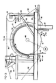
- Figs. 3-8 illustrate the details of construction of the drying system of Fig. 2 in greater detail. It should be understood,'however, that the drying system of Fig. 1 is constructed in an identical manner, with the exception that the dryer felt web 32 and associated rolls are not provided.
- the drum 14 is mounted for rotation on hollow shafts 48 by a mounting arrangement (not shown). Steam is supplied through shafts 48 such that the drum 14 is heated.
- An electrostatic means for subjecting the web of material to a static electrical field at the drying station includes frame means consisting of a pair of nonconductive supports 50 which extend circumferentially around drum 14. Supports 50 are spaced apart in a direction parallel to the axis of rotation of the drum 14 by a distance at least as great as the width of the moisture bearing web 10. Supports 50 are mounted on mounting structure 52 which also provide support for the rollers associated with the dryer felt web 32.
- a plurality of electrodes, each comprising an electrode wire 54, extend between the supports 50 and are connected to receive static electrical potentials for creation of the desired static electrical field.
- Nonconductive supports 50 are attached to support bars 56 by bolts 58 which extend through nonconductive supports 50 and bars 56 to engage nuts 60.
- Support bars 56 are, in turn, secured to the support frame 52.
- a plurality of cross support members 62 extend between the support bars 56 and may be welded thereto.
- a dryer felt web release 63 is also mounted on support frame 52 to permit web 32 to be removed.
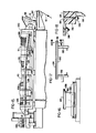
- Each of the electrode wires 54 extends between a bolt 64 secured in one of the nonconductive supports 50 and a threaded rod 66 secured in the opposing support 50.
- rod 66 is not threaded into support 50, but rather simply is received into an opening in the support.
- the rod 66 is held in position by the ension applied to the rod by means of the tensioned electrode wire 54 which is soldered to the end of rod 66.
- the tension of wire 54 may be adjusted by altering the position of rod 66 in support 50 by means of a pair of nuts 68, which also serve to engage a conductor 70 against washer 72.
- By applying an electrical potential to conductor 70 static electrical potentials may be applied to the electrode wires 54 as desired.
- a conductor 70 supplies a first static electrical potential to alternate electrodes along the web and is connected to alternate electrodes via the threaded bolts 66 extending from the right-hand nonconductive suppport 50.
- a second conductor may extend between each of the threaded rods 66 in the left hand support 50 of Fig. 8 so as to provide a means for supplying a second static electrical potential to each of the intermediate electrode wires 54. This second electrical conductor is removed in Fig. 8 for purposes of clarity.
- all of the electrode wires 54 may receive a static electrical potential on the order of 10000 volts.
- alternate electrode wires 54 may be connected to a high voltage 'source, with intermediate electrode wires remaining unconnected.
- a first static electrical potential on the order of 10000 volts, may be supplied to alternate electrode wires 54, with a second static electrical potential, such as ground potential, being supplied to the intermediate electrode wires.
- FIG. 9 illustrates third and fourth embodiments of the present invention.
- a liquid coating composition is applied to the web 10 at a coating station 74 where the web passes between a rotating coating roll 76 and an opposing roll 78. Excess coating fluid is removed from the web by a doctor 80. Web 10 then passes through a first drying station 12' and, subsequently through a second drying station 12" , guided by guide rolls 82, 84, 86, 88, 90, 92, and 94. The moisture content of the web 10 leaving the first drying station 12' is measured by gauge 96, while moisture content of the web 10 leaving the second drying station is measured by gauge 98.
- the third embodiment of the present nven- tion at drying station 12° is a drying system in which the heating means includes a plurality of radiant burners 100 positioned above the web 10. Burners 100 are gas fired infrared burners of standard design which radiate infrared energy onto the web 10 to effect evaporation of the moisture carried by the web. A plurality of electrodes 102 are positioned beneath the web and selected ones of the electrodes 102 receive static electrical potentials to produce a static electrical field which enhances evaporation of moisture from the web.
- each of the radiant burners 100 receives gas from a gas supply line 104 via an associated manifold 106.
- Each of the electrodes 102 is mounted to extend across the width of the web 10 by a pair of nonconductive electrode supports 108 which are attached to cross bars 109 extending between support legs 110.
- Web 10 is guided by rollers 82, 84, 86, and such additional rollers as may be needed, such that it passes above but does not contact the electrodes 102.
- Electrodes 102 along the web 10 extend alternately beyond the electrode supports 108 in opposite directions.
- Each of the L-shaped electrodes 102 is secured to supports 108 by screws 110 and each is electrically connected to lines 112 or l14 by bolts 116. and nuts 118, as shown in Figs. 13 and 14.
- An electrode structure is provided, therefore, in which alternate electrodes along the web path at the drying station can receive first and second static electrical potentials via lines 112 and 114, respectively.
- a drying rate increase averaging 1.6% was noted.
- Test results for the third embodiment of the invention are summarized in appendix C of the present application.
- the fourth embodiment of the present invention is depicted at drying station 12" in which the heating means comprises means for directing heated air against -the web 10.
- a closed drying tunnel 120 includes a manifold 122 to which heated air is supplied under pressure by appropriate apparatus (not shown).
- a plurality of electrode plates 124 are positioned in the tunnel dryer beneath the web 10 on the opposite side of the web from nozzles 126. Nozzles 126 communicate with the manifold 122 and direct heated air against the web 10. Static electrical potentials are applied to selected ones of the electrodes 124.
- Dryer tunnel 120 is generally closed but defines openings at each end so that web 10 may pass therethrough.
- a number of access openings 128 are provided to permit threading and cleaning the dryer. Openings 128 are covered during operation of the dryer.
- Each of the electrodes 124 comprises a sheet of electrically conductive material which extends across the width of the web and provides a substantial electrode area.
- Each of the electrodes 124 is mounted on a nonconductive support table 130 which, in turn, is secured to table supports 132.
- Bolts 134 and nuts 136 extend through the electrodes 124 and secure them to the supports 130.
- a bus bar 138 is attached to the edge of the electrodes 124, thus providing a means of supplying static electrical potentials to the electrodes.
- static potentials way be supplied to the electrodes by conductor wires connected to each of the electrodes.
- potentials ranging between 0 and 25000 volts were applied to .the alternate electrodes 124, with an average 5.7% increase in drying rate being noted.
- Corona discharge may break down or reduce the thickness of the boundary layer at the surface of the moisture bearing web.
- the charge dipole effect by which water or other liquid molecules are aligned with a field, making them more easily evaporated through the boundary layer, may also contribute to the increase in evaporation drying rate.
- the charge induced at the interface of the water and air may create an artificial surface tension which draws the volatile liquid to the surface more easily and thus enhances the evaporation rate.
- the electrostatic field may produce an attraction between the sheet and the drum which improves the heat transfer therebetween.
- drying system and method of the present invention have many applications. Drying of a moist paper web in a paper manufacturing operation may be enhanced by this technique.
- the present invention may be utilized to enhance evaporation of organic solvents or alcohols, as well as water.
- An electrostatic field may be utilized according to the present invention to dry a material web to which a liquid coating has been applied.
- the present invention may be used for drying a web of fabric, felt, or other porous material.
- ambient air may provide the necessary heating of the web in certain applications, without the need for an additional source of heat.
- the electrodes utilized may, if desired, extend only across a portion or portions of the web in order to provide moisture control in a direction perpendicular to the direction of web movement.
- Appendix A summarizes test results with a drum dryer including a dryer felt. In run 120, however, the drum felt was not utilized for purposes of comparison to run 119. In both runs, no voltage was applied to the electrode wires. During runs 121-131, alternate electrode wires were grounded while a negative potential of the level indicated was applied to the intermediate electrode wires.
- Appendix B summarizes test results for the unfelted drum dryer.
- a positive voltage was applied to all of the electrode wires.
- a positive voltage was applied only to alternate electrode wires, with intermediate electrode wires being permitted to float.
- a positive voltage was applied to alternate electrode wires, with intermediate electrode wires being grounded.
- a negative voltage was applied to alternate electrode wires, with intermediate electrode wires being permitted to float.
- a negative voltage was applied to alternate electrode wires, with intermediate electrode wires being grounded.
- Appendix C summarizes the test results obtained with the radiant infrared drying embodiment.
- a positive potential was applied to all of the electrode bars.
- a positive potential was applied to alternate electrode bars, with intermediate electrode bars being grounded.
- runs 100-101 several of the "upstream" electrode bars were permitted to float, with the remaining electrode bars receiving a positive electrical potential.
- Appendix D summarizes the test results obtained utilizing the tunnel dryer configuration.
- a negative voltage was applied to the electrode plates.
- a positive voltage was applied to the electrode plates.
- a positive voltage was applied to the electrode plates, with an insulating plastic cover covering the surface of roller 88.
- a negative voltage was applied to the electrode plates with a plastic cover over roll 88.
- the first and alternate electrode plates were grounded while a positive voltage was applied to the other electrode plates.
Landscapes
- Engineering & Computer Science (AREA)
- Mechanical Engineering (AREA)
- General Engineering & Computer Science (AREA)
- Textile Engineering (AREA)
- Life Sciences & Earth Sciences (AREA)
- Microbiology (AREA)
- Drying Of Solid Materials (AREA)
Applications Claiming Priority (2)
| Application Number | Priority Date | Filing Date | Title |
|---|---|---|---|
| US132442 | 1980-03-21 | ||
| US06/132,442 US4359826A (en) | 1980-03-21 | 1980-03-21 | Drying system |
Publications (2)
| Publication Number | Publication Date |
|---|---|
| EP0036632A2 true EP0036632A2 (de) | 1981-09-30 |
| EP0036632A3 EP0036632A3 (de) | 1982-01-13 |
Family
ID=22454072
Family Applications (1)
| Application Number | Title | Priority Date | Filing Date |
|---|---|---|---|
| EP81102032A Withdrawn EP0036632A3 (de) | 1980-03-21 | 1981-03-19 | Trocknungssystem |
Country Status (7)
| Country | Link |
|---|---|
| US (1) | US4359826A (de) |
| EP (1) | EP0036632A3 (de) |
| JP (1) | JPS56168073A (de) |
| AU (1) | AU536581B2 (de) |
| CA (1) | CA1149158A (de) |
| ES (1) | ES8207630A1 (de) |
| FI (1) | FI810842A7 (de) |
Cited By (5)
| Publication number | Priority date | Publication date | Assignee | Title |
|---|---|---|---|---|
| US4551924A (en) * | 1972-06-16 | 1985-11-12 | Candor James T | Electrostatic method for treating material |
| EP0245500A4 (de) * | 1985-11-13 | 1988-03-21 | Radiant Technology Corp | Apparatur und verfahren zur schnellen beseitigung organischer stoffe aus dünnen schichten durch erhitzung in einem elektrischen feld. |
| EP0516924A1 (de) * | 1991-06-07 | 1992-12-09 | Eltex-Elektrostatik Gesellschaft mbH | Vorrichtung zur Erhöhung des Wärmeübergangs an Kühlwalzen von Offset-Rollenrotationsmaschinen |
| DE4227136A1 (de) * | 1992-08-17 | 1994-02-24 | Weitmann & Konrad Fa | Verfahren und Vorrichtung zum Anfeuchten einer bewegten Materialbahn, insbesondere einer bedruckten und anschliessend getrockneten Papierbahn |
| EP0740120A3 (de) * | 1995-04-28 | 1997-04-09 | Bernhard Ehret | Trocknungsvorrichtung für mit Druckfarben, Klebstoffen und vergleichbaren Medien versehene Papier- oder Kunststoffbahnen |
Families Citing this family (22)
| Publication number | Priority date | Publication date | Assignee | Title |
|---|---|---|---|---|
| US4654979A (en) * | 1985-07-22 | 1987-04-07 | Candor James T | Electrostatic method and apparatus for treating material |
| US4697353A (en) * | 1970-04-06 | 1987-10-06 | Candor James T | Electrostatic method and apparatus for treating material |
| US4467529A (en) * | 1972-06-16 | 1984-08-28 | Candor | Electrostatic method and apparatus for treating material |
| US4413425A (en) * | 1980-08-04 | 1983-11-08 | Candor James T | Method for thermal/vacuum drying a wet web of material |
| US4404754A (en) * | 1981-05-08 | 1983-09-20 | Candor James T | Electrostatic method for treating material |
| US4671758A (en) * | 1983-02-14 | 1987-06-09 | Dayco Products, Inc. | Apparatus for electrostatically orienting reinforcing particles in a layer of reinforced polymeric material |
| US4747920A (en) * | 1984-06-20 | 1988-05-31 | Battelle Memorial Institute | Solid-liquid separation process for fine particle suspensions by an electric and ultrasonic field |
| US5152838A (en) * | 1989-01-17 | 1992-10-06 | Polaroid Corporation | Coating fluid drying apparatus |
| US5114560A (en) * | 1989-08-28 | 1992-05-19 | Nagabhusan Senapati | Apparatus and method for removal of liquids |
| CH679931A5 (de) * | 1990-04-18 | 1992-05-15 | Brandwijk Systems Programming | |
| US5086570A (en) * | 1990-09-28 | 1992-02-11 | Screen Printing Enterprises, Inc. | Drying apparatus for screen process printing and coating |
| DE4112537C2 (de) * | 1991-04-17 | 1994-06-01 | Escher Wyss Gmbh | Vorrichtung zur Glätteerzeugung |
| US5309650A (en) * | 1991-08-29 | 1994-05-10 | Abb Flakt, Inc. | Method and apparatus for ventilating a paint baking oven |
| US5235757A (en) * | 1991-08-29 | 1993-08-17 | Abb Flakt, Inc. | Method and apparatus for distributing airflow in a paint baking oven convection zone |
| CA2078290A1 (en) * | 1991-10-24 | 1993-04-25 | W.R. Grace & Co.-Conn. | Combination infrared and air flotation dryer |
| JPH0542922U (ja) * | 1991-11-01 | 1993-06-11 | 三菱重工業株式会社 | 天井埋込形空気調和機 |
| GB9414856D0 (en) * | 1994-07-22 | 1994-09-14 | Tmci Uk Ltd | Production of reconstituted tobacco sheet |
| DE19525453A1 (de) * | 1995-07-13 | 1997-01-16 | Eltex Elektrostatik Gmbh | Vorrichtung zum Ablösen der gasförmigen laminaren Grenzschicht |
| US5659972A (en) * | 1995-10-06 | 1997-08-26 | Avery Dennison Corporation | Apparatus and method for drying or curing web materials and coatings |
| WO2010141587A1 (en) | 2009-06-05 | 2010-12-09 | Megtec Systems, Inc. | Improved infrared float bar |
| JP6052083B2 (ja) * | 2013-07-12 | 2016-12-27 | トヨタ自動車株式会社 | 乾燥装置、乾燥方法、及び電池の製造方法 |
| FR3030584B1 (fr) * | 2014-12-17 | 2019-05-10 | Andritz Perfojet Sas | Installation d'extraction d'eau |
Family Cites Families (46)
| Publication number | Priority date | Publication date | Assignee | Title |
|---|---|---|---|---|
| US894070A (en) * | 1905-06-27 | 1908-07-21 | Hoechst Ag | Extraction of water or other liquid from mineral, vegetable, and animal substances. |
| US2042145A (en) * | 1931-03-05 | 1936-05-26 | William A Darrah | Process of evaporating and equipment therefor |
| FR760078A (fr) | 1933-08-25 | 1934-02-16 | Nouveau procédé permettant d'éviter le maculage dans l'impression et appareil pour la mise en oeuvre du procédé | |
| US2740756A (en) * | 1951-04-19 | 1956-04-03 | Albert G Thomas | Electrical drying system |
| US3082735A (en) * | 1960-09-20 | 1963-03-26 | Columbia Ribbon & Carbon | Apparatus for feeding and coating a web |
| US3000106A (en) * | 1957-03-20 | 1961-09-19 | West Virginia Pulp & Paper Co | Apparatus for drying paper by electrical conductivity |
| US3330136A (en) * | 1966-03-07 | 1967-07-11 | Robert R Candor | Laundry machine with suction means for washing and drying |
| US3238750A (en) * | 1962-08-27 | 1966-03-08 | Robert R Candor | Laundry machine |
| US3755911A (en) * | 1962-08-27 | 1973-09-04 | R Candor | Liquid removing apparatus and method |
| US3405452A (en) * | 1967-05-18 | 1968-10-15 | Robert R. Candor | Laundry drying apparatus or the like using electrostatic method and means |
| US3266164A (en) * | 1963-04-03 | 1966-08-16 | Fitchburg Paper | Drying pulp and paper by a high frequency electric field |
| US3355812A (en) * | 1965-08-04 | 1967-12-05 | Fitchburg Paper | Drying by high frequency electric field |
| US3470621A (en) * | 1966-05-11 | 1969-10-07 | Fitchburg Paper Co | Material treatment apparatus and method using a high frequency field |
| US3357108A (en) * | 1966-05-11 | 1967-12-12 | Fitchburg Paper | Mobile dielectric drying apparatus with energy source coupling means |
| US3442026A (en) * | 1966-08-11 | 1969-05-06 | Du Pont | Drum drying of polymeric material |
| US3449230A (en) * | 1966-11-08 | 1969-06-10 | Turner Brothers Asbest | Manufacture of asbestos products |
| US3546065A (en) * | 1967-12-29 | 1970-12-08 | Kimberly Clark Co | Corona discharge applied directly to creping surface to increase adhesion of web to surface |
| US3470716A (en) * | 1968-01-31 | 1969-10-07 | Robert R Candor | Electrostatic apparatus |
| US3491456A (en) * | 1968-07-29 | 1970-01-27 | Robert R Candor | Electrostatic liquid removal apparatus and method |
| US3543408A (en) * | 1968-10-21 | 1970-12-01 | Robert R Candor | Liquid removing apparatus and method |
| US3633282A (en) * | 1969-03-17 | 1972-01-11 | Robert R Candor | Liquid-removing apparatus and method |
| US3757426A (en) * | 1969-07-07 | 1973-09-11 | R Candor | Liquid removing method |
| US3641680A (en) * | 1970-06-01 | 1972-02-15 | Robert R Candor | Liquid-removing apparatus and method |
| US3705847A (en) * | 1970-09-21 | 1972-12-12 | Weyerhaeuser Co | Method for forming a uniform continuous web of paper |
| US3670606A (en) * | 1970-10-12 | 1972-06-20 | Inter Probe | Method and apparatus for cooling the workpiece and/or the cutting tools of a machining apparatus |
| US3735175A (en) * | 1971-03-15 | 1973-05-22 | Inter Probe | Method and apparatus for removing heat from within a vacuum and from within a mass |
| US3722105A (en) * | 1971-07-06 | 1973-03-27 | Owens Illinois Inc | Apparatus and method for applying radio frequency energy to a moving web of material |
| US3771233A (en) * | 1972-01-14 | 1973-11-13 | Trw Inc | Electrostatic enhancement of evaporation |
| US4057482A (en) * | 1972-06-16 | 1977-11-08 | Candor James T | Apparatus for removing liquid from liquid bearing material |
| US3965581A (en) * | 1972-06-16 | 1976-06-29 | Candor James T | Liquid removing method and apparatus |
| US3999302A (en) * | 1972-06-16 | 1976-12-28 | Candor James T | Liquid removing method and apparatus |
| US3893898A (en) * | 1972-06-16 | 1975-07-08 | James T Candor | Method for removing and/or separating particles from fluid containing the same |
| US4283862A (en) * | 1972-06-16 | 1981-08-18 | Candor James T | Electrostatic method and apparatus for treating material |
| US4081342A (en) * | 1972-06-16 | 1978-03-28 | Candor James T | Electrostatic method for treating material |
| US3795605A (en) * | 1972-06-16 | 1974-03-05 | J Candor | Method and apparatus for removing and/or separating particles from fluid containing the same |
| US4033841A (en) * | 1972-06-16 | 1977-07-05 | Candor James T | Liquid removing method and apparatus |
| CH568798A5 (de) * | 1973-04-18 | 1975-11-14 | Spengler Walter | |
| US3977937A (en) * | 1973-10-10 | 1976-08-31 | Candor James T | System for making a non-woven sheet by creating an electrostatic field action |
| US4060449A (en) * | 1973-10-10 | 1977-11-29 | Candor James T | Electrostatic method and apparatus for making a patterned, non-woven sheet |
| US4189845A (en) * | 1973-10-10 | 1980-02-26 | Candor James T | Method and apparatus for electrostatically forming a layer of material from a slurry thereof |
| US4003819A (en) * | 1974-01-25 | 1977-01-18 | J. M. Huber Corporation | Filtration of solids suspension enhanced by applied DC potential |
| US4110189A (en) * | 1974-07-05 | 1978-08-29 | J. M. Huber Corporation | Electro-osmotic/phoretic process for concentrating clay |
| US4050162A (en) * | 1975-01-15 | 1977-09-27 | Candor James T | Method and apparatus for removing liquid from liquid bearing material |
| US4135307A (en) * | 1976-06-11 | 1979-01-23 | Candor James T | Method and apparatus for removing liquid from liquid bearing material |
| US4111773A (en) * | 1976-10-15 | 1978-09-05 | Candor James T | Electrostatic method and apparatus for treating material |
| US4115233A (en) * | 1976-12-27 | 1978-09-19 | Monsanto Company | Treatment of aqueous dispersions |
-
1980
- 1980-03-21 US US06/132,442 patent/US4359826A/en not_active Expired - Lifetime
-
1981
- 1981-02-09 AU AU67103/81A patent/AU536581B2/en not_active Ceased
- 1981-03-17 JP JP3734581A patent/JPS56168073A/ja active Pending
- 1981-03-18 FI FI810842A patent/FI810842A7/fi not_active Application Discontinuation
- 1981-03-19 CA CA000373441A patent/CA1149158A/en not_active Expired
- 1981-03-19 EP EP81102032A patent/EP0036632A3/de not_active Withdrawn
- 1981-03-20 ES ES500578A patent/ES8207630A1/es not_active Expired
Cited By (6)
| Publication number | Priority date | Publication date | Assignee | Title |
|---|---|---|---|---|
| US4551924A (en) * | 1972-06-16 | 1985-11-12 | Candor James T | Electrostatic method for treating material |
| EP0245500A4 (de) * | 1985-11-13 | 1988-03-21 | Radiant Technology Corp | Apparatur und verfahren zur schnellen beseitigung organischer stoffe aus dünnen schichten durch erhitzung in einem elektrischen feld. |
| EP0516924A1 (de) * | 1991-06-07 | 1992-12-09 | Eltex-Elektrostatik Gesellschaft mbH | Vorrichtung zur Erhöhung des Wärmeübergangs an Kühlwalzen von Offset-Rollenrotationsmaschinen |
| DE4227136A1 (de) * | 1992-08-17 | 1994-02-24 | Weitmann & Konrad Fa | Verfahren und Vorrichtung zum Anfeuchten einer bewegten Materialbahn, insbesondere einer bedruckten und anschliessend getrockneten Papierbahn |
| DE4227136C3 (de) * | 1992-08-17 | 1998-08-13 | Weitmann & Konrad Fa | Verfahren und Vorrichtung zum Befeuchten einer bedruckten und anschließend thermisch getrockneten, bewegten Materialbahn, insbesondere Papierbahn |
| EP0740120A3 (de) * | 1995-04-28 | 1997-04-09 | Bernhard Ehret | Trocknungsvorrichtung für mit Druckfarben, Klebstoffen und vergleichbaren Medien versehene Papier- oder Kunststoffbahnen |
Also Published As
| Publication number | Publication date |
|---|---|
| ES500578A0 (es) | 1982-09-16 |
| ES8207630A1 (es) | 1982-09-16 |
| AU6710381A (en) | 1981-09-24 |
| US4359826A (en) | 1982-11-23 |
| FI810842L (fi) | 1981-09-22 |
| EP0036632A3 (de) | 1982-01-13 |
| JPS56168073A (en) | 1981-12-24 |
| FI810842A7 (fi) | 1981-09-22 |
| AU536581B2 (en) | 1984-05-10 |
| CA1149158A (en) | 1983-07-05 |
Similar Documents
| Publication | Publication Date | Title |
|---|---|---|
| EP0036632A2 (de) | Trocknungssystem | |
| US4112586A (en) | Method of drying a cardboard or a paper web and drying device for applying this method | |
| US4153560A (en) | Corona device and method for using same | |
| KR950014480A (ko) | 제지기계의 건조기부 및 종이웨브의 건조방법. | |
| SE8301421D0 (sv) | Forfarande och anordning for torkning av en pappersbana el dyl | |
| US3467541A (en) | Method and apparatus for moisturizing web material | |
| US2919495A (en) | Process of papermaking | |
| US2824383A (en) | Apparatus and method for electrically heating wet porous sheets | |
| US3633282A (en) | Liquid-removing apparatus and method | |
| US4413425A (en) | Method for thermal/vacuum drying a wet web of material | |
| US4060382A (en) | Method and device for dye transfer printing | |
| US3283415A (en) | Paper drying apparatus | |
| FI98232C (fi) | Kalanteri aineradan, erityisesti paperiradan käsittelemiseksi | |
| ZA817066B (en) | A method of ventilating cylinder pockets in a cylinder dryer and apparatus for carrying out the method | |
| US3399460A (en) | Process and apparatus for moisture content de-peaking and equalization | |
| US4574413A (en) | Methods and apparatus for employing electrical conductivity for fixing dye to carpets | |
| FI74062C (fi) | Foerfarande och anordning foer minskning hoegfrekvent elenergi av fuktighetsdifferenserna hos en roerlig bana medelst. | |
| KR100544452B1 (ko) | 건조부 장치 | |
| US2007551A (en) | Method of and apparatus for making paper board | |
| FI82872C (fi) | Anlaeggning foer upphettning av ban- eller skivformigt dielektriskt material eller foer saenkning av dess fukthalt. | |
| US4506452A (en) | Method and apparatus for RF drying of coated articles | |
| US3266164A (en) | Drying pulp and paper by a high frequency electric field | |
| US1515614A (en) | Method and machine for drying paper | |
| DE2020600A1 (de) | Beseitigung von elektrischen Aufladungen | |
| JP2622288B2 (ja) | コータ乾燥装置 |
Legal Events
| Date | Code | Title | Description |
|---|---|---|---|
| PUAI | Public reference made under article 153(3) epc to a published international application that has entered the european phase |
Free format text: ORIGINAL CODE: 0009012 |
|
| AK | Designated contracting states |
Designated state(s): DE FR GB IT SE |
|
| PUAL | Search report despatched |
Free format text: ORIGINAL CODE: 0009013 |
|
| AK | Designated contracting states |
Designated state(s): DE FR GB IT SE |
|
| 17P | Request for examination filed |
Effective date: 19820702 |
|
| STAA | Information on the status of an ep patent application or granted ep patent |
Free format text: STATUS: THE APPLICATION IS DEEMED TO BE WITHDRAWN |
|
| 18D | Application deemed to be withdrawn |
Effective date: 19841001 |
|
| RIN1 | Information on inventor provided before grant (corrected) |
Inventor name: ROUNSLEY, ROBERT R. |