EP0036187A1 - Head readjustment assembly for a video tape recorder - Google Patents
Head readjustment assembly for a video tape recorder Download PDFInfo
- Publication number
- EP0036187A1 EP0036187A1 EP81101839A EP81101839A EP0036187A1 EP 0036187 A1 EP0036187 A1 EP 0036187A1 EP 81101839 A EP81101839 A EP 81101839A EP 81101839 A EP81101839 A EP 81101839A EP 0036187 A1 EP0036187 A1 EP 0036187A1
- Authority
- EP
- European Patent Office
- Prior art keywords
- bending strip
- thickness
- piezoceramic
- carrier plate
- magnetic head
- Prior art date
- Legal status (The legal status is an assumption and is not a legal conclusion. Google has not performed a legal analysis and makes no representation as to the accuracy of the status listed.)
- Withdrawn
Links
Images
Classifications
-
- G—PHYSICS
- G11—INFORMATION STORAGE
- G11B—INFORMATION STORAGE BASED ON RELATIVE MOVEMENT BETWEEN RECORD CARRIER AND TRANSDUCER
- G11B5/00—Recording by magnetisation or demagnetisation of a record carrier; Reproducing by magnetic means; Record carriers therefor
- G11B5/48—Disposition or mounting of heads or head supports relative to record carriers ; arrangements of heads, e.g. for scanning the record carrier to increase the relative speed
- G11B5/56—Disposition or mounting of heads or head supports relative to record carriers ; arrangements of heads, e.g. for scanning the record carrier to increase the relative speed with provision for moving the head support for the purpose of adjusting the position of the head relative to the record carrier, e.g. manual adjustment for azimuth correction or track centering
-
- G—PHYSICS
- G11—INFORMATION STORAGE
- G11B—INFORMATION STORAGE BASED ON RELATIVE MOVEMENT BETWEEN RECORD CARRIER AND TRANSDUCER
- G11B5/00—Recording by magnetisation or demagnetisation of a record carrier; Reproducing by magnetic means; Record carriers therefor
- G11B5/48—Disposition or mounting of heads or head supports relative to record carriers ; arrangements of heads, e.g. for scanning the record carrier to increase the relative speed
- G11B5/58—Disposition or mounting of heads or head supports relative to record carriers ; arrangements of heads, e.g. for scanning the record carrier to increase the relative speed with provision for moving the head for the purpose of maintaining alignment of the head relative to the record carrier during transducing operation, e.g. to compensate for surface irregularities of the latter or for track following
- G11B5/584—Disposition or mounting of heads or head supports relative to record carriers ; arrangements of heads, e.g. for scanning the record carrier to increase the relative speed with provision for moving the head for the purpose of maintaining alignment of the head relative to the record carrier during transducing operation, e.g. to compensate for surface irregularities of the latter or for track following for track following on tapes
- G11B5/588—Disposition or mounting of heads or head supports relative to record carriers ; arrangements of heads, e.g. for scanning the record carrier to increase the relative speed with provision for moving the head for the purpose of maintaining alignment of the head relative to the record carrier during transducing operation, e.g. to compensate for surface irregularities of the latter or for track following for track following on tapes by controlling the position of the rotating heads
- G11B5/592—Disposition or mounting of heads or head supports relative to record carriers ; arrangements of heads, e.g. for scanning the record carrier to increase the relative speed with provision for moving the head for the purpose of maintaining alignment of the head relative to the record carrier during transducing operation, e.g. to compensate for surface irregularities of the latter or for track following for track following on tapes by controlling the position of the rotating heads using bimorph elements supporting the heads
Definitions
- the invention relates to an actuator for a video tape device, as specified in the preamble of claim 1.
- VCR video g asse tten recorder
- actuators are used with which the mechanical position of the magnetic heads installed in the video device can be electrically adjusted.
- Such designs provide that the respective magnetic head is attached to the electrically movable end of a piezoceramic bending strip, which executes adjustable deflection from a rest position due to the piezoelectric effect by applying differently high electrical voltage to these bending strips.
- "Such a piezoceramic bending strip consists of two piezoceramic foils in strip form which are firmly connected to one another, this bilaminar body having an elongated rectangular shape.
- the invention consists in a combination of a plurality of features or dimensions which are coordinated with one another and with one another several times, which overall result in an optimal solution to the task at hand.
- the carrier sheet located between the piezoceramic foils made of roughened aluminum or titanium, a light metal, on the one hand enables the two piezoceramic foils of the bilaminar structure of the piezoelectric bending system of the strip to be spaced apart without any disturbing effects Resilience or a flow behavior occur again.
- the neutral fiber in an actuator according to the invention lies outside the adhesive layers, compared to known actuators with bilaminar structure.
- thermosetting adhesive which also complies with the economic framework that can be manufactured. Together with the specified dimensions, not only can the required minimum degree of response speed of the bending strip according to the invention be maintained, but moreover a very high speed value can also be achieved with the selection of the carrier plate according to the claims.
- the bending strip according to the invention is thus to be used both for rapid changes in the position of the magnetic head and its deflection is very constant with the long-term unchanged deflection required.
- the breakthroughs of the carrier plate provided according to one embodiment allow a (further) increase in speed without loss of responsiveness and long-term constancy.
- the bending strip of an actuator according to the invention is designated, which apart from the magnetic head 10 consists of the two piezoceramic foils 2 and 3 and the carrier plate 4.
- 5 with dashed lines indicates a clamping device in its entirety, in which the left-hand end of the bending strip 1 in the figure is firmly clamped.
- the length of the bending strip 1 within this clamping 5 and the clamping pressure are such that bending of the electrically excited bending strip within the clamping range is practically impossible.
- the total length L of the non-clamped portion of the bending strip 1 is greater than 20 times the total thickness D of the bending strip 1 (L> 20. D).
- thermosetting adhesive such as e.g. AV8 from Ciba, firmly and permanently glued together.
- Electrode coatings 21 and 31 with connections 121 and 131 are applied to the respective outer surfaces of the films 2 and 3.
- An electrical terminal of the T r ägerbleches is designated 141st These connections are used to supply the electrical voltage used for the controllable deflection of the magnetic head 10.
- the bending strip 1 has a trapezoidal shape, the width B 1 at the clamping end of the bending strip 1 on the left in the figure Is 5 to 2 times the width B 2 of the opposite tapered end of the active part of the bending strip.
- the active part of the bending strip is to be understood as the part outside the clamping in which piezoceramic foil is present.
- the carrier plate 4 projects with a comparatively short length beyond the area of the piezoceramic foils 2 and 3, the magnetic head 10 being attached to the bending strip 1 at this portion.
- FIG. 2 shows a plan view of a carrier plate 4 ', as is expediently to be used in a bending strip 1 according to FIG.
- the solid bonding of the carrier sheet 4 'to the piezoceramic foils 2 and 3 takes place essentially in the area outside the openings (41). It is only of insignificant disadvantage if the cavities in the interior of the bending strip 1 through the openings in the carrier plate 4 'are partially filled with adhesive.
Abstract
Description
Die Erfindung bezieht sich auf einen Aktuator für ein Video-Bandgerät, wie er im Oberbegriff des Patentanspruchs 1 angegeben ist.The invention relates to an actuator for a video tape device, as specified in the preamble of
Aus dem Stand der Technik sind Video-Bandgeräte und insbesondere Video-gassetten-Recorder (VCR) bekannt, in denen Magnetköpfe zum Aufzeichnen und zum Abtasten der in Spuren aufzuzeichnenden bzw. aufgezeichneten Video-Signale dienen. Zur Ausnutzung der verfügbaren Bandfläche ist vorgesehen, daß die Aufzeichnungsspuren, z.B. Schrägspuren, auf dem Band dicht aneinanderliegen, wobei die Abstände zwischen den einzelnen Spuren sogar kleiner als die Spurbreite sein können. Diese Aufzeichnungstechnik erfordert außerordentlich hohe Genauigkeit der mechanischen Halterung und Lage der aufzeichnenden und/oder abtastenden Magnetköpfe.From the prior art video tape recorders and in particular video g asse tten recorder (VCR) are known in which the recorded magnetic heads for recording and scanning in the tracks or recorded video signals are used. In order to utilize the available tape area, it is provided that the recording tracks, for example inclined tracks, lie close together on the tape, and the distances between the individual tracks can even be smaller than the track width. This recording technique requires extremely high accuracy of the mechanical mounting and position of the recording and / or scanning magnetic heads.
Es ist praktisch unmöglich, einen Magnetkopf in einem wie oben angegebenen Gerät von vornherein so genau justiert anzubringen, daß die Lage dieses Magnetkopfes im Betrieb fehlerfrei ist. Erst recht ist es praktisch .unmöglich, daß eine vielleicht anfänglich korrekte Lage des Magnetkopfes auch noch nach längerer Gebrauchsdauer ausreichend fehlerfrei ist.It is practically impossible to mount a magnetic head in a device as specified above from the start so precisely that the position of this magnetic head is correct during operation. It is even more practically impossible that an initially correct position of the magnetic head is sufficiently error-free even after a long period of use.
Dem Stand der Technik gemäß werden Aktuatoren verwendet, mit denen die im Video-Gerät angebrachten Magnetköpfe in ihrer mechanischen Lage elektrisch nachjustiert werden können. Solche Ausführungen sehen vor, daß der jeweilige Magnetkopf auf dem elektrisch bewegbaren Ende eines piezokeramischen Biegestreifens angebracht ist, der durch Anlegen verschieden hoher elektrischer Spannung an diesen Biegestreifen vermöge des piezoelektrischen Effekts einstellbar große Auslenkung aus einer Ruhelage ausführt. "Ein solcher piezokeramischer Biegestreifen besteht aus zwei miteinander fest verbundenen piezokeramischen Folien in Streifenform, wobei dieser bilaminare Körper längliche Rechteckform hat.According to the state of the art, actuators are used with which the mechanical position of the magnetic heads installed in the video device can be electrically adjusted. Such designs provide that the respective magnetic head is attached to the electrically movable end of a piezoceramic bending strip, which executes adjustable deflection from a rest position due to the piezoelectric effect by applying differently high electrical voltage to these bending strips. "Such a piezoceramic bending strip consists of two piezoceramic foils in strip form which are firmly connected to one another, this bilaminar body having an elongated rectangular shape.
Es ist eine Aufgabe der vorliegenden Erfindung, einen solchen Aktuator anzugeben, der bei möglichst geringer Baugröße, d.h. Baulänge, einerseits und mit möglichst geringer elektrischer Leistung andererseits über den vorgeschriebenen Auslenkungsbereich hinweg einstellbar ist, wobei die Ansprechgeschwindigkeit, d.h. der erfor- derliche Zeitraum für steuerbare Änderung von einem Auslenkungszustand zum nächsten Auslenkungszustand, möglichst gering sein soll. Dem entspricht eine hohe Nachführgeschwindigkeit des anzugebenden neuen Aktuators.It is an object of the present invention to provide such an actuator which, with the smallest possible size, ie overall length, on the one hand and with the lowest possible electrical power on the other hand, can be set beyond the prescribed deflection range, the response speed, ie the required period for controllable change from one state of deflection to the next state of deflection, should be as small as possible. This corresponds to a high tracking speed of the new actuator to be specified.
Diese Aufgabe wird mit einem wie im Oberbegriff des Patentanspruchs 1 angegebenen Aktuator erfindungsgemäß.mit den Merkmalen des Kennzeichens des Patentanspruchs 1 gelöste Weitere Ausgestaltungen und Weiterbildungen der Erfindung gehen aus den Unteransprüchen hervor.This object is achieved according to the invention with an actuator as specified in the preamble of
Die Erfindung besteht in einer Kombination einer Mehrzahl von aufeinander und mehrfach untereinander abgestimmten Merkmalen bzw. Bemessungen, die insgesamt eine opti-_ male Lösung der gestellten Aufgabe ergeben. Das zwischen den piezokeramischen Folien befindliche Trägerblech aus an seinen Oberflächen aufgerauhtem Aluminium oder Titan, einem leichten Metall, ermöglicht einerseits eine Abstandshalterung der beiden piezokeramischen Folien des bilaminaren Aufbaues des piezoelektrischen Biegesystems des Streifens, ohne daß damit störende Effekte einer Nachgiebigkeit bzw, eines Fließverhaltens neu auftreten. Augrund dieses Abstandes bei gleich dicken piezokeramischen Folien liegt die neutrale Faser bei einem erfindungsgemäßen Aktuator - vergleichsweise zu bekannten Aktuatoren mit bilaminaren Aufbau - außerhalb der Klebschichten. Dazu gehört auch die Verwendung des heißhärtenden Klebers, der außerdem auch den zu setzenden Rahmen der wirtschaftlichen Herstellbarkeit einhält. Zusammen mit den angegebenen Bemessungen läßt sich mit der anspruchsgemäßen Auswahl des Trägerbleches nicht nur das notwendige Mindestmaß der Ansprechgeschwindigkeit des erfindungsgemäßen Biegestreifens einhalten, sondern darüber hinaus sogar ein sehr großer Geschwindigkeitswert erreichen. Der erfindungsgemäße Biegestreifen ist somit sowohl für rasche Änderungen der Lage des Magnetkopfes zu verwenden als auch in seiner Auslenkung sehr konstant bei geforderter langzeitiger unveränderter Auslenkung. Die gemäß einer Ausgestaltung vorgesehenen Durchbrüche des Trägerbleches lassen eine (weitere) Erhöhung der Geschwindigkeit ohne Einbuße an Ansprechempfindlichkeit und Langzeitkonstanz erreichen.The invention consists in a combination of a plurality of features or dimensions which are coordinated with one another and with one another several times, which overall result in an optimal solution to the task at hand. The carrier sheet located between the piezoceramic foils made of roughened aluminum or titanium, a light metal, on the one hand enables the two piezoceramic foils of the bilaminar structure of the piezoelectric bending system of the strip to be spaced apart without any disturbing effects Resilience or a flow behavior occur again. On the basis of this distance in the case of piezoceramic foils of the same thickness, the neutral fiber in an actuator according to the invention lies outside the adhesive layers, compared to known actuators with bilaminar structure. This also includes the use of the thermosetting adhesive, which also complies with the economic framework that can be manufactured. Together with the specified dimensions, not only can the required minimum degree of response speed of the bending strip according to the invention be maintained, but moreover a very high speed value can also be achieved with the selection of the carrier plate according to the claims. The bending strip according to the invention is thus to be used both for rapid changes in the position of the magnetic head and its deflection is very constant with the long-term unchanged deflection required. The breakthroughs of the carrier plate provided according to one embodiment allow a (further) increase in speed without loss of responsiveness and long-term constancy.
Weitere Erläuterungen der Erfindung gehen aus der nachfolgenden Figurenbeschreibung eines bevorzugten Ausführungsbeispiels und seiner Weiterbildung hervor.
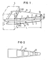
- Fig.1 zeigt eine perspektivische, nur angenähert maßstäbliche Prinzipskizze des Biegestreifens eines erfindungsgemäßen Aktuators.
- Fig.2 zeigt in Aufsicht ein Trägerblech mit gemäß einer Ausbildung vorgesehenen Durchbrüchen.
- 1 shows a perspective sketch of the bending strip of an actuator according to the invention, which is only approximately to scale.
- 2 shows a top view of a carrier plate with openings provided according to an embodiment.
Mit 1 ist der Biegestreifen eines erfindungsgemäßen Aktuators bezeichnet, der abgesehen von dem Magnetkopf 10 aus den beiden piezokeramischen Folien 2 und 3 und dem Trägerblech 4 besteht. Mit 5 ist gestrichelt eine Einspannvorrichtung in ihrer Gesamtheit angedeutet, in der das in der Figur linksseitige Ende des Biegestreifens 1 fest eingespannt ist. Die Länge des Biegestreifens 1 innerhalb dieser Einspannung 5 und der Einspanndruck sind so bemessen, daß eine Biegung des elektrisch angeregten Biegestreifens innerhalb des Einspannbereiches praktisch ausgeschlossen ist.With 1 the bending strip of an actuator according to the invention is designated, which apart from the
Die Dicke d1 der piezokeramischen Folie 2 und die Dicke d'1 der oiezokeramischen Folie 3 sind wenigstens angenähert gleich groß und kleiner als 0,2 mm. Für die Dicke d2 des Trägerbleches 4 ist vorgesehen
- 0,5 d1 < d2 < 2. d1.
- 0.5 d 1 <d 2 <2. d 1 .
Die Gesamtlänge L des nichteingespannten Anteils des Biegestreifens 1 ist größer als das 20-fache der Gesamtdicke D des Biegestreifens 1 (L>20. D).The total length L of the non-clamped portion of the
Die jeweils aufeinanderliegenden Oberflächen der piezokeramischen Folien 2 und 3 einerseits und des Trägerbleches 4 andererseits sind mit einem heißhärtenden Kleber, wie z.B. AV8 der Fa. Ciba, miteinander fest und dauerhaft verklebt.The respective superimposed surfaces of the
Auf den jeweils äußeren Oberflächen der Folien 2 und 3 sind Elektrodenbeschichtungen 21 und 31 mit Anschlüssen 121 und 131 angebracht. Ein elektrischer Anschluß des Trägerbleches ist mit 141 bezeichnet. Diese Anschlüsse dienen zur Zuführung der zur steuerbaren Auslenkung des Magnetkopfes 10 dienenden elektrischen Spannung.
Wie aus der Fig.1 ersichtlich, hat der Biegestreifen 1 eine Trapezform, wobei die Breite B1 an dem in der Figur linksseitigen Einspann-Ende des Biegestreifens 1 das 5- bis 2-fache der Breite B2 des gegenüberliegenden verjüngten Endes des aktiven Teiles des Biegestreifens ist. Unter aktivem Teil des Biegestreifens ist derjenige Anteil außerhalb der Einspannung zu verstehen, bei dem piezokeramische Folie vorhanden ist. Bei der speziellen Ausführungsform der Fig.1 ragt das Trägerblech 4 mit einer vergleichsweise geringen Länge über den Bereich der piezokeramischen Folien 2 und 3 hinaus, wobei an diesem Anteil der Magnetkopf 10 am Biegestreifen 1 befestigt ist. Eine solche Ausführungsform hat deshalb besonderen Vorteil, weil sich ein wie bekannter Magnetkopf leichter an Metall als an Keramik, und zwar mit hoher Präzision der Abmessung, anbringen läßt. Ein erfindungsgemäßer Biegestreifen hat z.B. die Abmessungen d1= d'1= d2 " 150/um mit Aluminium als Trägerblech und B1= 7 mm und B2 = 3 mm sowie L = 13 mm.As can be seen from FIG. 1, the
Fig.2 zeigt eine Aufsicht eines Trägerbleches 4', wie es zweckmäßigerweise in einem Biegestreifen 1 nach Fig.2 zu verwenden ist. Die feste Verklebung des Trägerbleches 4' mit den piezokeramischen Folien 2 und 3 erfolgt im wesentlichen im Bereich außerhalb der Durchbrüche (41). Es ist nur von unwesentlichem Nachteil, wenn die im Innern des Biegestreifens 1 durch die Durch-brüche des Trägerbleches 4' gegebenen Hohlräume zu einem Anteil mit Klebstoff angefüllt sind.2 shows a plan view of a carrier plate 4 ', as is expediently to be used in a
Claims (3)
Applications Claiming Priority (2)
| Application Number | Priority Date | Filing Date | Title |
|---|---|---|---|
| DE3010580 | 1980-03-19 | ||
| DE19803010580 DE3010580A1 (en) | 1980-03-19 | 1980-03-19 | VIDEO TAPE ACTUATOR |
Publications (1)
| Publication Number | Publication Date |
|---|---|
| EP0036187A1 true EP0036187A1 (en) | 1981-09-23 |
Family
ID=6097692
Family Applications (1)
| Application Number | Title | Priority Date | Filing Date |
|---|---|---|---|
| EP81101839A Withdrawn EP0036187A1 (en) | 1980-03-19 | 1981-03-12 | Head readjustment assembly for a video tape recorder |
Country Status (5)
| Country | Link |
|---|---|
| EP (1) | EP0036187A1 (en) |
| JP (1) | JPS56148724A (en) |
| BR (1) | BR8101593A (en) |
| DE (1) | DE3010580A1 (en) |
| PT (1) | PT72690B (en) |
Cited By (6)
| Publication number | Priority date | Publication date | Assignee | Title |
|---|---|---|---|---|
| EP0591885A2 (en) * | 1992-10-06 | 1994-04-13 | Matsushita Electric Industrial Co., Ltd. | Piezoelectric head actuator |
| EP0626212A2 (en) * | 1993-05-28 | 1994-11-30 | Matsushita Electric Industrial Co., Ltd. | Holding structure of piezoelectric vibrator and manufacturing method therefor |
| WO1997045663A1 (en) * | 1996-05-29 | 1997-12-04 | Flight Refuelling Limited | A flapper valve |
| US5963397A (en) * | 1995-06-07 | 1999-10-05 | International Business Machines Corporation | Ceramic suspension bent by stressed patch |
| US6049443A (en) * | 1995-06-07 | 2000-04-11 | International Business Machines Corporation | Suspension bent by stressed patch |
| FR3090208A1 (en) * | 2018-12-18 | 2020-06-19 | Commissariat A L'energie Atomique Et Aux Energies Alternatives | ELECTROMECHANICAL MICROSYSTEM COMPRISING AN ACTIVE ELEMENT PROVIDED WITH A STRUCTURED CORE LAYER |
Families Citing this family (2)
| Publication number | Priority date | Publication date | Assignee | Title |
|---|---|---|---|---|
| JPS63140660U (en) * | 1987-03-05 | 1988-09-16 | ||
| JPS64351U (en) * | 1987-06-19 | 1989-01-05 |
Citations (6)
| Publication number | Priority date | Publication date | Assignee | Title |
|---|---|---|---|---|
| DE2837104A1 (en) * | 1977-08-26 | 1979-03-01 | Sony Corp | SYSTEM FOR PLAYBACK OF A VIDEO SIGNAL RECORDED IN PARALLEL TRACK SECTIONS OF A RECORDING MEDIUM |
| DE2901677A1 (en) * | 1978-01-18 | 1979-07-19 | Silvano Dr Ing Matteini | DEVICE FOR DISPLAYING AND / OR CONTROLLING THE MATERIAL LEVEL IN A CYLINDRICAL TURNING FURNACE FOR INCINERATING WASTE |
| DE2915881A1 (en) * | 1978-04-19 | 1979-10-31 | Sony Corp | MAGNETIC RECORDING AND PLAYBACK DEVICE |
| DE2919391A1 (en) * | 1978-05-15 | 1979-11-22 | Sony Corp | SCANNING DEVICE, IN PARTICULAR FOR A VIDEO TAPE DEVICE |
| DE3016748A1 (en) * | 1979-05-02 | 1980-11-13 | Sony Corp | ELECTROMECHANICAL CONVERTER |
| DE3021430A1 (en) * | 1979-06-09 | 1980-12-18 | Sony Corp | DEFLECTABLE HOLDING DEVICE FOR AN ELECTROMAGNETIC CONVERTER |
-
1980
- 1980-03-19 DE DE19803010580 patent/DE3010580A1/en not_active Withdrawn
-
1981
- 1981-03-12 EP EP81101839A patent/EP0036187A1/en not_active Withdrawn
- 1981-03-18 BR BR8101593A patent/BR8101593A/en unknown
- 1981-03-18 JP JP3930081A patent/JPS56148724A/en active Pending
- 1981-03-18 PT PT7269081A patent/PT72690B/en unknown
Patent Citations (6)
| Publication number | Priority date | Publication date | Assignee | Title |
|---|---|---|---|---|
| DE2837104A1 (en) * | 1977-08-26 | 1979-03-01 | Sony Corp | SYSTEM FOR PLAYBACK OF A VIDEO SIGNAL RECORDED IN PARALLEL TRACK SECTIONS OF A RECORDING MEDIUM |
| DE2901677A1 (en) * | 1978-01-18 | 1979-07-19 | Silvano Dr Ing Matteini | DEVICE FOR DISPLAYING AND / OR CONTROLLING THE MATERIAL LEVEL IN A CYLINDRICAL TURNING FURNACE FOR INCINERATING WASTE |
| DE2915881A1 (en) * | 1978-04-19 | 1979-10-31 | Sony Corp | MAGNETIC RECORDING AND PLAYBACK DEVICE |
| DE2919391A1 (en) * | 1978-05-15 | 1979-11-22 | Sony Corp | SCANNING DEVICE, IN PARTICULAR FOR A VIDEO TAPE DEVICE |
| DE3016748A1 (en) * | 1979-05-02 | 1980-11-13 | Sony Corp | ELECTROMECHANICAL CONVERTER |
| DE3021430A1 (en) * | 1979-06-09 | 1980-12-18 | Sony Corp | DEFLECTABLE HOLDING DEVICE FOR AN ELECTROMAGNETIC CONVERTER |
Cited By (10)
| Publication number | Priority date | Publication date | Assignee | Title |
|---|---|---|---|---|
| EP0591885A2 (en) * | 1992-10-06 | 1994-04-13 | Matsushita Electric Industrial Co., Ltd. | Piezoelectric head actuator |
| EP0591885A3 (en) * | 1992-10-06 | 1995-02-01 | Matsushita Electric Ind Co Ltd | Piezoelectric head actuator. |
| EP0626212A2 (en) * | 1993-05-28 | 1994-11-30 | Matsushita Electric Industrial Co., Ltd. | Holding structure of piezoelectric vibrator and manufacturing method therefor |
| EP0626212A3 (en) * | 1993-05-28 | 1997-07-09 | Matsushita Electric Ind Co Ltd | Holding structure of piezoelectric vibrator and manufacturing method therefor. |
| US5963397A (en) * | 1995-06-07 | 1999-10-05 | International Business Machines Corporation | Ceramic suspension bent by stressed patch |
| US6049443A (en) * | 1995-06-07 | 2000-04-11 | International Business Machines Corporation | Suspension bent by stressed patch |
| WO1997045663A1 (en) * | 1996-05-29 | 1997-12-04 | Flight Refuelling Limited | A flapper valve |
| US6017016A (en) * | 1996-05-29 | 2000-01-25 | Flight Refueling Limited | Flapper valve |
| FR3090208A1 (en) * | 2018-12-18 | 2020-06-19 | Commissariat A L'energie Atomique Et Aux Energies Alternatives | ELECTROMECHANICAL MICROSYSTEM COMPRISING AN ACTIVE ELEMENT PROVIDED WITH A STRUCTURED CORE LAYER |
| EP3671873A1 (en) | 2018-12-18 | 2020-06-24 | Commissariat à l'énergie atomique et aux énergies alternatives | Electromechanical microsystem comprising an active element provided with a structured core layer |
Also Published As
| Publication number | Publication date |
|---|---|
| DE3010580A1 (en) | 1981-09-24 |
| BR8101593A (en) | 1981-09-22 |
| PT72690B (en) | 1982-03-22 |
| PT72690A (en) | 1981-04-01 |
| JPS56148724A (en) | 1981-11-18 |
Similar Documents
| Publication | Publication Date | Title |
|---|---|---|
| DE3016748C2 (en) | ||
| DE3902738C2 (en) | Nozzle flap device | |
| DE2828148C2 (en) | Bending arrangement | |
| DE19816909C2 (en) | Actuator with piezoelectric element and this actuator inserting head positioning mechanism | |
| EP0025092B1 (en) | Ultrasonic transducer assembly and process for its production | |
| DE2810459C3 (en) | Electrodynamic converter of mechanical vibrations into electrical signals and vice versa, stereo and monophonic sound heads and electrodynamic microphone | |
| DE3048773A1 (en) | MAGNETIC CONVERTER STRUCTURE WITH SEVERAL BRIDGES | |
| DE4435914C2 (en) | Piezoelectric drive for an ink jet recording head and method of manufacturing the same | |
| EP0036187A1 (en) | Head readjustment assembly for a video tape recorder | |
| DE19739494C2 (en) | Piezoelectric element and method of manufacturing the same | |
| DE60115709T2 (en) | An ink jet recording head and method of making the same | |
| DE3532615A1 (en) | ARRANGEMENT IN A HYDROPHONE | |
| DE3008464C2 (en) | Arrangement for deflecting a magnetic head in the transverse direction to a recording track of a recording medium | |
| DE1195356B (en) | Oscillation system for an electrodynamic converter | |
| DE3134480A1 (en) | DEVICE FOR A DEFLECTABLE MAGNETIC HEAD | |
| DE3225255A1 (en) | POWER TRANSFORMER WITH SPRING SUSPENSION | |
| DE2457816A1 (en) | ARTIFICIAL DIELECTRIC STRUCTURE AND METHOD OF MANUFACTURING THE SAME | |
| DE2927269C2 (en) | Piezoelectric drive element for writing nozzles in ink mosaic writing devices | |
| EP0822602B1 (en) | Device for the deformation of a support by electric or magnetic effects | |
| DE3313887A1 (en) | Tone generator | |
| DE3538632C2 (en) | ||
| DE3724349A1 (en) | Rotary transformer for a recorder | |
| DE69836235T2 (en) | Acoustic surface wave system | |
| DE3346811C2 (en) | ||
| DE3419256A1 (en) | ELECTRIC-ACOUSTIC CONVERTER DEVICE |
Legal Events
| Date | Code | Title | Description |
|---|---|---|---|
| PUAI | Public reference made under article 153(3) epc to a published international application that has entered the european phase |
Free format text: ORIGINAL CODE: 0009012 |
|
| AK | Designated contracting states |
Designated state(s): CH DE FR GB IT NL SE |
|
| STAA | Information on the status of an ep patent application or granted ep patent |
Free format text: STATUS: THE APPLICATION IS DEEMED TO BE WITHDRAWN |
|
| 18D | Application deemed to be withdrawn |
Effective date: 19820827 |
|
| RIN1 | Information on inventor provided before grant (corrected) |
Inventor name: MEIXNER, HANS, DR. DIPL.-PHYS. Inventor name: KLEINSCHMIDT, PETER, DIPL.-PHYS. |