EP0036041A2 - Heat exchanger for roof, façade, barrier and the like - Google Patents
Heat exchanger for roof, façade, barrier and the like Download PDFInfo
- Publication number
- EP0036041A2 EP0036041A2 EP80107655A EP80107655A EP0036041A2 EP 0036041 A2 EP0036041 A2 EP 0036041A2 EP 80107655 A EP80107655 A EP 80107655A EP 80107655 A EP80107655 A EP 80107655A EP 0036041 A2 EP0036041 A2 EP 0036041A2
- Authority
- EP
- European Patent Office
- Prior art keywords
- heat exchanger
- exchanger according
- extruded profile
- tube
- profile
- Prior art date
- Legal status (The legal status is an assumption and is not a legal conclusion. Google has not performed a legal analysis and makes no representation as to the accuracy of the status listed.)
- Granted
Links
- 230000004888 barrier function Effects 0.000 title 1
- 229910052751 metal Inorganic materials 0.000 claims abstract description 34
- 239000002184 metal Substances 0.000 claims abstract description 32
- 238000003801 milling Methods 0.000 claims description 14
- 238000003466 welding Methods 0.000 claims description 5
- 239000004744 fabric Substances 0.000 claims description 4
- 239000004033 plastic Substances 0.000 claims description 4
- 229920003023 plastic Polymers 0.000 claims description 4
- 239000010426 asphalt Substances 0.000 claims description 3
- 239000011324 bead Substances 0.000 claims description 3
- 210000002445 nipple Anatomy 0.000 claims description 3
- 238000003780 insertion Methods 0.000 claims description 2
- 230000037431 insertion Effects 0.000 claims description 2
- 230000003746 surface roughness Effects 0.000 claims 1
- 238000001125 extrusion Methods 0.000 abstract description 4
- 239000011229 interlayer Substances 0.000 abstract 1
- 239000000853 adhesive Substances 0.000 description 6
- 230000001070 adhesive effect Effects 0.000 description 6
- 238000004519 manufacturing process Methods 0.000 description 6
- 239000006072 paste Substances 0.000 description 6
- 238000010276 construction Methods 0.000 description 5
- 238000009826 distribution Methods 0.000 description 5
- 239000000463 material Substances 0.000 description 5
- 238000003825 pressing Methods 0.000 description 5
- 238000010422 painting Methods 0.000 description 4
- 239000006096 absorbing agent Substances 0.000 description 3
- 238000005253 cladding Methods 0.000 description 3
- 238000000576 coating method Methods 0.000 description 3
- 238000005520 cutting process Methods 0.000 description 3
- 238000007789 sealing Methods 0.000 description 3
- 238000012546 transfer Methods 0.000 description 3
- 229910000838 Al alloy Inorganic materials 0.000 description 2
- 229910052782 aluminium Inorganic materials 0.000 description 2
- XAGFODPZIPBFFR-UHFFFAOYSA-N aluminium Chemical compound [Al] XAGFODPZIPBFFR-UHFFFAOYSA-N 0.000 description 2
- 238000007743 anodising Methods 0.000 description 2
- 238000005452 bending Methods 0.000 description 2
- 238000005260 corrosion Methods 0.000 description 2
- 230000007797 corrosion Effects 0.000 description 2
- 239000013529 heat transfer fluid Substances 0.000 description 2
- 238000000034 method Methods 0.000 description 2
- 238000004080 punching Methods 0.000 description 2
- XLYOFNOQVPJJNP-UHFFFAOYSA-N water Substances O XLYOFNOQVPJJNP-UHFFFAOYSA-N 0.000 description 2
- 229910000831 Steel Inorganic materials 0.000 description 1
- 238000010521 absorption reaction Methods 0.000 description 1
- 230000006978 adaptation Effects 0.000 description 1
- 238000004026 adhesive bonding Methods 0.000 description 1
- 230000015572 biosynthetic process Effects 0.000 description 1
- 239000003990 capacitor Substances 0.000 description 1
- 238000009833 condensation Methods 0.000 description 1
- 230000005494 condensation Effects 0.000 description 1
- 238000001816 cooling Methods 0.000 description 1
- 239000012809 cooling fluid Substances 0.000 description 1
- 238000013461 design Methods 0.000 description 1
- 238000006073 displacement reaction Methods 0.000 description 1
- 230000000694 effects Effects 0.000 description 1
- 238000004553 extrusion of metal Methods 0.000 description 1
- 238000009434 installation Methods 0.000 description 1
- 239000007788 liquid Substances 0.000 description 1
- 230000001050 lubricating effect Effects 0.000 description 1
- 150000002739 metals Chemical class 0.000 description 1
- 239000000203 mixture Substances 0.000 description 1
- 238000012946 outsourcing Methods 0.000 description 1
- 239000003973 paint Substances 0.000 description 1
- 229910000679 solder Inorganic materials 0.000 description 1
- 239000010935 stainless steel Substances 0.000 description 1
- 229910001220 stainless steel Inorganic materials 0.000 description 1
- 230000003068 static effect Effects 0.000 description 1
- 239000010959 steel Substances 0.000 description 1
- 239000003351 stiffener Substances 0.000 description 1
- 230000037072 sun protection Effects 0.000 description 1
- 238000004381 surface treatment Methods 0.000 description 1
- 238000012549 training Methods 0.000 description 1
Images
Classifications
-
- F—MECHANICAL ENGINEERING; LIGHTING; HEATING; WEAPONS; BLASTING
- F24—HEATING; RANGES; VENTILATING
- F24S—SOLAR HEAT COLLECTORS; SOLAR HEAT SYSTEMS
- F24S80/00—Details, accessories or component parts of solar heat collectors not provided for in groups F24S10/00-F24S70/00
- F24S80/30—Arrangements for connecting the fluid circuits of solar collectors with each other or with other components, e.g. pipe connections; Fluid distributing means, e.g. headers
-
- F—MECHANICAL ENGINEERING; LIGHTING; HEATING; WEAPONS; BLASTING
- F24—HEATING; RANGES; VENTILATING
- F24S—SOLAR HEAT COLLECTORS; SOLAR HEAT SYSTEMS
- F24S20/00—Solar heat collectors specially adapted for particular uses or environments
- F24S20/60—Solar heat collectors integrated in fixed constructions, e.g. in buildings
- F24S20/66—Solar heat collectors integrated in fixed constructions, e.g. in buildings in the form of facade constructions, e.g. wall constructions
-
- F—MECHANICAL ENGINEERING; LIGHTING; HEATING; WEAPONS; BLASTING
- F24—HEATING; RANGES; VENTILATING
- F24S—SOLAR HEAT COLLECTORS; SOLAR HEAT SYSTEMS
- F24S10/00—Solar heat collectors using working fluids
- F24S10/70—Solar heat collectors using working fluids the working fluids being conveyed through tubular absorbing conduits
- F24S10/75—Solar heat collectors using working fluids the working fluids being conveyed through tubular absorbing conduits with enlarged surfaces, e.g. with protrusions or corrugations
-
- F—MECHANICAL ENGINEERING; LIGHTING; HEATING; WEAPONS; BLASTING
- F24—HEATING; RANGES; VENTILATING
- F24S—SOLAR HEAT COLLECTORS; SOLAR HEAT SYSTEMS
- F24S20/00—Solar heat collectors specially adapted for particular uses or environments
- F24S20/60—Solar heat collectors integrated in fixed constructions, e.g. in buildings
- F24S20/67—Solar heat collectors integrated in fixed constructions, e.g. in buildings in the form of roof constructions
-
- F—MECHANICAL ENGINEERING; LIGHTING; HEATING; WEAPONS; BLASTING
- F24—HEATING; RANGES; VENTILATING
- F24S—SOLAR HEAT COLLECTORS; SOLAR HEAT SYSTEMS
- F24S60/00—Arrangements for storing heat collected by solar heat collectors
- F24S60/30—Arrangements for storing heat collected by solar heat collectors storing heat in liquids
-
- F—MECHANICAL ENGINEERING; LIGHTING; HEATING; WEAPONS; BLASTING
- F28—HEAT EXCHANGE IN GENERAL
- F28F—DETAILS OF HEAT-EXCHANGE AND HEAT-TRANSFER APPARATUS, OF GENERAL APPLICATION
- F28F13/00—Arrangements for modifying heat-transfer, e.g. increasing, decreasing
- F28F2013/005—Thermal joints
- F28F2013/006—Heat conductive materials
-
- Y—GENERAL TAGGING OF NEW TECHNOLOGICAL DEVELOPMENTS; GENERAL TAGGING OF CROSS-SECTIONAL TECHNOLOGIES SPANNING OVER SEVERAL SECTIONS OF THE IPC; TECHNICAL SUBJECTS COVERED BY FORMER USPC CROSS-REFERENCE ART COLLECTIONS [XRACs] AND DIGESTS
- Y02—TECHNOLOGIES OR APPLICATIONS FOR MITIGATION OR ADAPTATION AGAINST CLIMATE CHANGE
- Y02B—CLIMATE CHANGE MITIGATION TECHNOLOGIES RELATED TO BUILDINGS, e.g. HOUSING, HOUSE APPLIANCES OR RELATED END-USER APPLICATIONS
- Y02B10/00—Integration of renewable energy sources in buildings
- Y02B10/20—Solar thermal
-
- Y—GENERAL TAGGING OF NEW TECHNOLOGICAL DEVELOPMENTS; GENERAL TAGGING OF CROSS-SECTIONAL TECHNOLOGIES SPANNING OVER SEVERAL SECTIONS OF THE IPC; TECHNICAL SUBJECTS COVERED BY FORMER USPC CROSS-REFERENCE ART COLLECTIONS [XRACs] AND DIGESTS
- Y02—TECHNOLOGIES OR APPLICATIONS FOR MITIGATION OR ADAPTATION AGAINST CLIMATE CHANGE
- Y02E—REDUCTION OF GREENHOUSE GAS [GHG] EMISSIONS, RELATED TO ENERGY GENERATION, TRANSMISSION OR DISTRIBUTION
- Y02E10/00—Energy generation through renewable energy sources
- Y02E10/40—Solar thermal energy, e.g. solar towers
- Y02E10/44—Heat exchange systems
Definitions
- the invention relates to heat exchangers for house roofs, facades, fences or the like with a heat exchanger plate and at least one heat exchanger tube.
- extruded profiles require an unnecessarily large wall thickness which is not required to absorb the loads which occur and thus represents an uneconomical use of material.
- the connection of the pressed-in hollow channels to the further distribution pipes can only be accomplished by costly measures.
- Right Angular channels in the extruded profile must first be closed at the ends by welding, gluing and the like in order to be able to attach a pipe connection nipple to them.
- tubes can be clamped in omega-shaped grooves in the sheet-metal strip, but manufacturing tolerances lead to air gaps and thus to incomplete heat transfer. Air gaps between the pipe and sheet metal can be filled with thermal pastes, adhesives or bitumen to improve heat transfer and possibly avoid crevice corrosion, but these costly manufacturing processes can only be carried out at the factory and not on the construction site.
- Aluminum roofs or facades may not be used in their original state due to building regulations, but must be painted or anodized beforehand.
- painting a distinction is made between the piece painting and the so-called coil coating process, in which the paint is applied quickly and inexpensively using rollers.
- the coil coating process is not suitable for all sheet thicknesses.
- connection elements of a roof or facade that are not activated as a heat exchanger surface must also be designed with the same groove arrangement for adaptation reasons, without them being used Actual recording of the heat transfer tubes serve.
- Another disadvantage is that relatively expensive special roll form sets or pressing tools are required to produce such grooved sheet metal strips.
- Heat exchanger plate elements which are made of roll-clad material according to the so-called Rollbond or Z-Bond process, have the disadvantage that they have to be made of easily deformable material and are therefore hardly usable as resilient or walkable roof or facade elements without additional stiffeners are.
- elements of this type of manufacture also require costly piece painting or anodizing, since bare metal sheets cannot be used for aesthetic reasons.
- the object of the present innovation is to create large-area heat exchanger plate elements for roof coverings, facade claddings, fencing, screens, sun protection systems, soundproof walls that are easy to install and that can be painted using the coil coating process, and that can simultaneously serve to collect and dissipate heat.
- the heat exchanger tube consists of an T-profile-like extruded profile, the flange plane of which is designed as a contact surface, and in that the tube is connected to the sheet metal via an elastic intermediate layer.
- contact surface is intended to indicate that the special design between the flange level of the extruded profile and the heat exchanger sheet is important for the subject of the invention.
- the contact surface is to ensure high thermal conductivity between the heat exchanger parts mentioned by local cold welding.
- the combination of these contact surfaces with the special thermal paste has led to surprising successes in heat conduction in house roofs, facades or fences. Because of the diverse external force effects, in particular the vibrating load from wind forces, it is advantageous to use rigid attachment of the extruded profile by press riveting in combination with the local cold welding of the elastic intermediate layer.
- the extruded profile is fastened with a resilient sheet metal strip in the roll-formed sheet metal profile, the ends of the resilient sheet metal strip engaging in beads of the roll-formed sheet metal profile.
- the roll-formed sheet metal profile can also be designed as a hollow profile, it being provided for further improvement of the heat conduction between the heat exchanger sheet and the heat exchanger tube that the extruded profile is designed in the manner of a double-T beam, in which the tube is arranged in the central web.
- An advantageous composition of the elastic intermediate layer is characterized in that the intermediate layer consists of a heat-conducting paste on plastic or bitumen bases with embedded metal bodies.
- the T-shaped or double-T-shaped heat exchanger tubes have a round outer circumference at the ends.
- the tube part of the T-shaped or double-T-shaped heat exchanger tube can be interrupted, a connector being expediently fastened in the interruption of the tube part.
- the ends of the extruded profile can be connected to a distribution pipe, a rubber fabric hose or a corrugated pipe with a pipe fitting.
- a device for producing the extruded profile according to the invention advantageously consists in that a cylindrical hollow body is provided with milling teeth on its end face and carries an inner centering mandrel at the opposite end, which is guided in the tube end of the extruded profile.
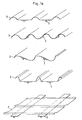
- FIG. 1 shows, for example, various sheet cross sections A, B, C, D, E of this type, the sheet metal strip being able to be deformed by folding or roll forming before the connection work, in order to be able to meet special static or aesthetic requirements.
- Both vertically structured sheet metal elements, FIG. 1 A - D, and horizontally structured sheet metal elements (FIG. 1 E) can be created.
- a permanently elastic heat-conducting paste 6 is applied and reduced to the optimum thickness using pressure (see FIG. 1 b).
- So-called press rivets as shown in FIG. 2 and FIG. 3, serve as additional mechanical securing of the adhesive connection between sheet metal A and profile 1.
- the press rivets are carried out with special cutting press punches in order to ensure local punching with little deformation to achieve both components and a hooking 7-10 in the cutting area. '
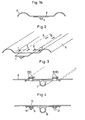
- FIG. 4 Another mechanical fuse is shown in Figure 4; here threaded welding studs 11, 12 are welded on one side according to the capacitor discharge method without damaging the painted opposite side 13. Instead of a screw lock 14, a deformation of the upper bolt end can also take place here, so that the extruded profile 15 is held non-detachably.
- a further mechanical securing of the adhesive connection can take place by means of sheet metal strips 1.6, which are clamped in corresponding beads 18 formed in the sheet profile 17 and press the extruded profile 19 continuously by spring tension on the sheet profile.
- the sheet metal strips are advantageously folded on one side, since this considerably facilitates the pressing in (FIG. 5).
- the additional mechanical connections not only have the task of securing the adhesive connections against loosening, but are also intended to simplify the manufacturing process, since the glued components are thereby held in their position during the curing of the adhesive or the thermal paste can be packed right after the manufacturing process without paying particular attention to an outsourcing period.
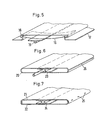
- FIG. 6 shows a further possibility of creating wide-area heat exchanger plates 20 which, for decorative purposes, must have visible surfaces which are closed on all sides. These are e.g. used for sun visors, privacy fences, soundproof walls, etc.
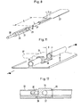
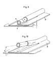
- a heat transfer fluid or a cooling fluid is introduced through the absorber extruded profiles. For this it is necessary to connect the components to each other and also to the distribution lines. This is done according to the invention in that, according to FIG. 8, the profile flanges 27 are removed at the end by sawing or punching to a limited length L and are then rounded off outside by means of special cutters, so that further pipe systems and pipe connecting elements can be connected.
- This special milling cutter is part of the overall system and, according to the invention, as shown in FIG. 8, consists of a cylindrical hollow body 28, which is provided with corresponding milling teeth on the end face 29 and carries an internal centering mandrel 30 at the opposite end, which at the same time also serves as a clamping mandrel in a hand drill or milling unit. It has proven to be advantageous to allow the centering mandrel to protrude approx. 10 mm beyond the end milling surface in order to obtain a locking mechanism when milling and thus to minimize the milling path.
- the milling sleeve 28 has longitudinal openings 31 so that cooling or lubricating liquids have access to the centering mandrel during the milling process. These longitudinal openings also serve for better chip removal.
- FIGS. 9 and 10 A further possibility of obtaining a perfect round milling on such an extruded profile 32 without having to carry out prior removal of the profile flanges is shown in FIGS. 9 and 10.
- the distance A of the pipe center M from the flange surface 0 must be greater than half the pipe diameter d by at least the milling sleeve wall thickness s.
- the free pipe length can be increased in order to allow bending up to a bending angle ⁇ in order to be able to fasten corresponding pipe connection members.
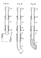
- Figures 11 and 12 show a further possibility of profile formation.
- pressing the screw 35 with a slot or better with a hexagon socket in the nut washer 38 results in the fitting being pressed onto the sealing surface 36.
- the pipe connection 37 is rotated 90 ° to the longitudinal axis of the profile.
- a further innovation of the heat exchanger construction system consists in a simple combination of tube elements known per se, which enables simple and quick assembly of the individual, end-processed absorber profiles on the further distribution lines. So far it has been known that such multifunctional heat exchanger elements can be connected to the distribution lines by means of a rubber hose via hose clamps: Likewise known are connections which were created by means of commercially available cutting ring fittings. All connection systems have the disadvantage that considerable manual forces must be applied during assembly, the Ar increase workload unnecessarily. For safety reasons, please note: Hose clamps clamp the rubber hose so locally that it can be damaged and that the connection is not completely sealed.
- a pipe connection can be both rigid by means of a press fitting and with the interposition of elastic pipe members such as Rubber fabric hose or corrugated steel pipes can be created without having to have more than three components at hand.
- the rigid connection consists of a press fitting, FIG. 13, the cylindrical press fitting 41 being designed such that it can be pushed over the entire length continuously over the pipe element 42 to be connected with a sealing ring 49, 50.
- the inseparable connection is pressed using known electro-mechanical pressing tongs.
- elastic pipe members as shown in FIG. 14 and alternatively in FIG. 15, are interposed.
- a rubber fabric hose 43 is additionally required, in each of which a push-in pipe part 44 is pressed in at the end, which has a pipe cross-section 45 on one side and a fir tree-like toothing 46 on the other side of the pipe outside. The tightness is ensured by the tensile stresses occurring in the hose, slipping out of the insert tube part is prevented by the barbs of the fir-tree-like teeth.
- FIG. 15 Another possibility of a connection via an elastic pipe member is shown in FIG. 15.
- a corrugated metal hose 47 of relatively thin wall thickness is provided at the end with soldered or glued-in pipe parts 48, which in turn are connected by means of press fitting 41.
- the end of the metal-wide tube 47 is widened like a cup.
- the metal corrugated hose can also be provided on the inside with stiffening sleeves which enable a direct connection of the metal corrugated hose to the press fittings that can be pushed over.
- a sealing paste or the like is placed between the stiffening sleeve and the metal corrugated hose end before insertion.
Landscapes
- Engineering & Computer Science (AREA)
- Chemical & Material Sciences (AREA)
- Sustainable Development (AREA)
- Physics & Mathematics (AREA)
- Sustainable Energy (AREA)
- Thermal Sciences (AREA)
- Life Sciences & Earth Sciences (AREA)
- Combustion & Propulsion (AREA)
- Mechanical Engineering (AREA)
- General Engineering & Computer Science (AREA)
- Dispersion Chemistry (AREA)
- Heat-Exchange Devices With Radiators And Conduit Assemblies (AREA)
- Roof Covering Using Slabs Or Stiff Sheets (AREA)
- Extrusion Moulding Of Plastics Or The Like (AREA)
- Fencing (AREA)
Abstract
Description
Die Erfindung betrifft Wärmetauscher für Hausdächer, Fassaden, Zäune oder dergleichen mit einem Wärmetauscherblech und mindestens einem Wärmetauscherrohr.The invention relates to heat exchangers for house roofs, facades, fences or the like with a heat exchanger plate and at least one heat exchanger tube.
Bekannt sind verschiedene Luft-Wasser-Wärmetauscherelemente aus Metallen und Kunststoffen, die sowohl vornehmlich der Wärmeabsorption als auch der Gebäude-Dacheindeckung als auch Fassadenverkleidung dienen.Various air-water heat exchanger elements made of metals and plastics are known, which serve primarily for heat absorption as well as building roof covering and facade cladding.
Öbliche Herstellungsverfahren für Fassadenverkleidungen sind das Strangpressen von Metallen, vorwiegend von Aluminiumlegierungen, sowie das Extrudieren von Kunststoffen in Hohlprofilen, siehe DE-Gm 78 20 719, DE-OS 27 15 759, DE-OS 25 29095, DE-OS 26 17 040, DE-OS 28 04 301. Ferner gibt es die Blech-Rohrbauweise, wobei die Rohre in omegaförmige Nuten des Bleches eingeklemmt werden, siehe DE-OS 25 12 226, DE-OS 26 33 862, DE-Gm 75 40 889.Common manufacturing processes for facade cladding are the extrusion of metals, predominantly aluminum alloys, and the extrusion of plastics in hollow profiles, see DE-Gm 78 20 719, DE-OS 27 15 759, DE-OS 25 29095, DE-OS 26 17 040, DE-OS 28 04 301. There is also the sheet metal tube construction, the tubes being clamped in omega-shaped grooves in the sheet, see DE-OS 25 12 226, DE-OS 26 33 862, DE-Gm 75 40 889.
Diese bekannten Bauelemente weisen jedoch Nachteile auf. So erfordern Strangpreßprofile aus preßtechnischen Gründen, besonders bei breitflächiger Ausbildung, eine unnötig große Wanddicke, die zur Aufnahme der auftretenden Belastungen nicht benötigt wird und somit unwirtschaftlichen Materialeinsatz darstellt. Der Anschluß der eingepreßten Hohlkanäle an die weiterführenden Verteilerrohre ist hierbei nur durch kostenaufwendige Maßnahmen zu bewerkstelligen. Bei rechteckigen Kanälen im Strangpreßprofil müssen diese erst jeweils endseitig durch Schweißen, Kleben und dergleichen verschlossen werden, um hieran einen Rohranschlußnippel anbringen zu können.However, these known components have disadvantages. For extrusion reasons, especially in the case of wide-area training, extruded profiles require an unnecessarily large wall thickness which is not required to absorb the loads which occur and thus represents an uneconomical use of material. The connection of the pressed-in hollow channels to the further distribution pipes can only be accomplished by costly measures. Right Angular channels in the extruded profile must first be closed at the ends by welding, gluing and the like in order to be able to attach a pipe connection nipple to them.
Bei rohrförmigen Kanälen im Strangpreßprofil können endseitig weiterführende Rohre nur dann montiert werden, wenn vorher spezielle Anschlußteile mit Gewinde und entsprechenden Dichtungen eingedreht werden, siehe DE-AS 27 56660, oder Rohrnippel angeschweißt oder eingeklebt werden. StrangpreBprofilkonstruktionen, insbesondere solche aus Aluminium, erfordern aus ästhetischen Gründen eine relativ teure Oberflächenbehandlung durch Anodisieren oder Stücklackieren. Die sichtbare Oberfläche kann lediglich in Profillängsrichtung durch Anpressen von Rippen oder Noppen optisch aufgelockert werden.In the case of tubular ducts in the extruded profile, further-extending pipes can only be fitted at the end if special connecting parts with threads and corresponding seals have been screwed in beforehand, see DE-AS 27 56660, or pipe nipples are welded or glued on. Extruded profile constructions, especially those made of aluminum, require a relatively expensive surface treatment by anodizing or piece painting for aesthetic reasons. The visible surface can only be loosened optically in the longitudinal direction of the profile by pressing ribs or knobs.
Bei der Rohr-Blechbauweise können Rohre in omegaförmige Nuten des Blechbandes zwar eingeklemmt werden, jedoch führen Fertigungstoleranzen zu Luftspalten und hierdurch zu unvollkommenem Wärmeübergang. Luftspalte zwischen Rohr und Blech können zwar mit Wärmeleitpasten, Klebstoffen oder Bitumen ausgefüllt werden, um den Wärmeübergang zu verbessern und evtl. Spaltkorrosion zu vermeiden, jedoch sind diese kostenaufwendigen Fertigungsvorgänge nur werkseitig und nicht auf der Baustelle duchführbar.In the case of the tube-sheet metal construction, tubes can be clamped in omega-shaped grooves in the sheet-metal strip, but manufacturing tolerances lead to air gaps and thus to incomplete heat transfer. Air gaps between the pipe and sheet metal can be filled with thermal pastes, adhesives or bitumen to improve heat transfer and possibly avoid crevice corrosion, but these costly manufacturing processes can only be carried out at the factory and not on the construction site.
Aluminiumdächer oder -fassaden dürfen aus baubehördlichen Bestimmungen nicht im Originalzustand eingesetzt werden, sondern müssen vorher lackiert oder eloxiert-werden. Beim Lackieren unterscheidet man die Stücklackierung vom sogenannten coil-coating-Verfahren, bei dem die Farbe mit Walzen schnell und kostengünstig aufgetragen wird. Das coil-coating-Verfahren ist aber nicht für alle Blechdicken geeignet.Aluminum roofs or facades may not be used in their original state due to building regulations, but must be painted or anodized beforehand. When painting, a distinction is made between the piece painting and the so-called coil coating process, in which the paint is applied quickly and inexpensively using rollers. However, the coil coating process is not suitable for all sheet thicknesses.
Die ästhetischen Anforderungen an die eingangs genannten Wärmetauscher sind unterschiedlicher Natur. Daher muß das zu entwickelnde System möglichst flexibel an den jeweiligen Käuferwunsch angepaßt werden können. Es muß auch eine asymmetrische Aufteilung der Wärmetauscherflächen möglich sein.The aesthetic requirements for the heat exchangers mentioned at the outset are different in nature. Therefore, the system to be developed must be able to be adapted as flexibly as possible to the respective buyer's request. An asymmetrical division of the heat exchanger surfaces must also be possible.
Wie oben erwähnt, sind die im Blech eingeformten Omega-Nuten meist aus ästhetischen Gesichtspunkten unerwünscht, zum anderen müssen alle Anschlußelemente eines Daches oder einer Fassade, die nicht als Wärmetauscherfläche aktiviert sind, ebenfalls aus Anpassungsgründen mit der gleichen Nutenanordnung ausgebildet sein, ohne daß sie zur eigentlichen Aufnahme der Wärmeträgerrohre dienen. Ein weiterer Nachteil besteht darin, daß zur Herstellung derartiger mit Nuten versehener Blechbänder relativ teure spezielle Rollformsätze oder Preßwerkzeuge erforderlich werden. Wärmetauscherplattenelemente, die aus walzplattiertem Material nach dem sogenannten Rollbond- oder Z-Bond-Verfahren hergestellt sind, weisen den Nachteil auf, daß sie aus gut verformbarem Material hergestellt werden müssen und dadurch als belastbare bzw. begehbare Dach- oder Fassadenelemente ohne zusätzliche Aussteifungen kaum einsetzbar sind. Außerdem verlangen Elemente dieser Herstellungsart ebenfalls kostenaufwendige Stücklackierung bzw. Anodisierung, da metallblanke Bleche aus ästhetischen Gründen nicht einsetzbar sind.As mentioned above, the omega grooves formed in the sheet are mostly undesirable from an aesthetic point of view, on the other hand, all connection elements of a roof or facade that are not activated as a heat exchanger surface must also be designed with the same groove arrangement for adaptation reasons, without them being used Actual recording of the heat transfer tubes serve. Another disadvantage is that relatively expensive special roll form sets or pressing tools are required to produce such grooved sheet metal strips. Heat exchanger plate elements, which are made of roll-clad material according to the so-called Rollbond or Z-Bond process, have the disadvantage that they have to be made of easily deformable material and are therefore hardly usable as resilient or walkable roof or facade elements without additional stiffeners are. In addition, elements of this type of manufacture also require costly piece painting or anodizing, since bare metal sheets cannot be used for aesthetic reasons.
Der vorliegenden Neuerung liegt die Aufgabe zugrunde, einfach montierbare und im coil-coating-Verfahren lackierbare, ästhetisch wirkende großflächige Wärmetauscherplattenelemente für Dacheindeckungen, Fassadenverkleidungen, Einzäunungen, Sichtblenden, Sonnenschutzanlagen, Schallschutzwände zu schaffen, die gleichzeitig der Wärmesammlung und der Wärmeabgabe dienen können.The object of the present innovation is to create large-area heat exchanger plate elements for roof coverings, facade claddings, fencing, screens, sun protection systems, soundproof walls that are easy to install and that can be painted using the coil coating process, and that can simultaneously serve to collect and dissipate heat.
Dies wird erfindungsgemäß dadurch gelöst, daß bei einem Wärmetauscher der eingangs genannten Art das Wärmetauscherrohr aus einem T-'profilähnlichen Strangpreßprofil besteht, dessen Flanschebene als Kontaktfläche ausgebildet ist, und daß das Rohr mit dem Blech über eine elastische Zwischenlage verbunden ist.This is achieved according to the invention in that, in the case of a heat exchanger of the type mentioned at the outset, the heat exchanger tube consists of an T-profile-like extruded profile, the flange plane of which is designed as a contact surface, and in that the tube is connected to the sheet metal via an elastic intermediate layer.
Der Begriff Kontaktfläche soll andeuten, daß es bei dem Erfindungsgegenstand auf die besondere Ausbildung zwischen Flanschebene des Strangpreßprofils und Wärmetauscherblech ankommt. Die Kontaktfläche soll durch örtliche Kaltverschweißung eine hohe thermische Leitfähigkeit zwischen den genannten Wärmetauscherteilen sicherstellen. Insbesondere die Kombination dieser Kontaktflächen mit der besonderen Wärmeleitpaste-hat zu überraschenden Erfolgen bei der Wärmeleitung in Hausdächern, Fassaden oder Zäunen geführt. Wegen der vielfältigen äußeren Krafteinwirkungen insbesondere der schwingenden Belastung durch Windkräfte ist es vorteilhaft, eine starre Befestigung des Strangpreßprofils durch Preßnietung in Kombination mit der örtlichen KaltverSchweißung der elastischen Zwischenlage anzuwenden.The term contact surface is intended to indicate that the special design between the flange level of the extruded profile and the heat exchanger sheet is important for the subject of the invention. The contact surface is to ensure high thermal conductivity between the heat exchanger parts mentioned by local cold welding. In particular, the combination of these contact surfaces with the special thermal paste has led to surprising successes in heat conduction in house roofs, facades or fences. Because of the diverse external force effects, in particular the vibrating load from wind forces, it is advantageous to use rigid attachment of the extruded profile by press riveting in combination with the local cold welding of the elastic intermediate layer.
In einer besonderen Ausführungsform der Erfindung ist vorgesehen, daß das Strangpreßprofil mit einem federnden Blechstreifen im rollgeformten Blechprofil befestigt ist, wobei die Enden des federnden Blechstreifens in Sicken des rollgeformten Blechprofils eingreifen.In a special embodiment of the invention it is provided that the extruded profile is fastened with a resilient sheet metal strip in the roll-formed sheet metal profile, the ends of the resilient sheet metal strip engaging in beads of the roll-formed sheet metal profile.
Das rollgeformte Blechprofil kann auch als Hohlprofil ausgebildet sein, wobei zur weiteren Verbesserung der Wärmeleitung zwischen Wärmetauscherblech und Wärmetauscherrohr vorgesehen ist, daß das Strangpreßprofil nach Art eines Doppel-T-Trägers ausgebildet ist, bei dem das Rohr im Mittelsteg angeordnet ist. Eine vorteilhafte Zusammensetzung der elastischen Zwischenlage ist dadurch gekennzeichnet, daß die Zwischenschicht aus einer Wärmeleitpaste auf Kunststoff- oder Bitumenbasi's mit eingelagerten Metallkörperchen besteht.The roll-formed sheet metal profile can also be designed as a hollow profile, it being provided for further improvement of the heat conduction between the heat exchanger sheet and the heat exchanger tube that the extruded profile is designed in the manner of a double-T beam, in which the tube is arranged in the central web. An advantageous composition of the elastic intermediate layer is characterized in that the intermediate layer consists of a heat-conducting paste on plastic or bitumen bases with embedded metal bodies.
Für besondere Anschlußverbindungen ist es vorteilhaft, daß die T-förmigen bzw. doppel-T-förmigen Wärmetauscherrohre an den Enden einen runden Außenumfang aufweisen. Der Rohrteil des T-förmigen bzw. doppel-T-förmigen Wärmetauscherrohres kann unterbrochen werden, wobei in der Unterbrechung des Rohrteiles zweckmäßigerweise ein Anschlußstück befestigt ist.For special connection connections, it is advantageous that the T-shaped or double-T-shaped heat exchanger tubes have a round outer circumference at the ends. The tube part of the T-shaped or double-T-shaped heat exchanger tube can be interrupted, a connector being expediently fastened in the interruption of the tube part.
Die Enden des Strangpreßprofils können mit einem Rohrfitting an einem Verteilerrohr, einem Gummi-Gewebeschlauch oder einem Wellrohr angeschlossen sein.The ends of the extruded profile can be connected to a distribution pipe, a rubber fabric hose or a corrugated pipe with a pipe fitting.
Eine Vorrichtung zur Herstellung des erfindungsgemäßen Strangpreßprofils besteht vorteilhafterweise darin, daß ein zylinderförmiger Hohlkörper an seiner Stirnseite mit Fräszähnen versehen ist und am gegenüberliegenden Ende einen innenliegenden Zentrierdorn trägt, der im Rohrende des Strangpreßprofils geführt ist.A device for producing the extruded profile according to the invention advantageously consists in that a cylindrical hollow body is provided with milling teeth on its end face and carries an inner centering mandrel at the opposite end, which is guided in the tube end of the extruded profile.
Im folgenden wird die Erfindung anhand mehrerer Ausführungsbeispiele näher erläutert. Es zeigen:


Figur 1 zeigt beispielsweise verschiedene solcher Blechquerschnitte A, B, C, D, E, wobei das Blechband vor den Verbindungsarbeiten durch Abkanten oder Rollformen verformt werden kann, um besonderen statischen oder ästhetischen Erfordernissen gerecht werden zu können. Es können sowohl vertikal strukturierte Blechelemente, Figur 1 A - D, als auch horizontal strukturierte Blechelemente (Figur 1 E) geschaffen werden. Um eine gut wärmeleitfähige Verbindung zwischen dem Rohrprofil 1, 2, 3, 4, 5 und dem Bandmaterial bewerkstelligen zu können und zur Vermeidung eines Luftspaltes zwischen beiden Bauteilen, wird eine dauerelastische Wärmeleitpaste 6 aufgetragen und unter Druckaufwendung auf möglichst optimale Dicke verringert (siehe Figur 1 b). Als zusätzliche mechanische Sicherung der Klebverbindung zwischen Blech A und Profil 1 dienen sogenannte Preßnietungen, wie sie aus Figur 2 und Figur 3 hervorgehen. Die Preßnietungen werden mit besonderen Schnittpreßstempeln durchgeführt, um eine örtliche Durchstanzung mit geringer Verformung eines der beiden Bauteile und eine Verhakung 7 - 10 im Schnittbereich zu erreichen.'FIG. 1 shows, for example, various sheet cross sections A, B, C, D, E of this type, the sheet metal strip being able to be deformed by folding or roll forming before the connection work, in order to be able to meet special static or aesthetic requirements. Both vertically structured sheet metal elements, FIG. 1 A - D, and horizontally structured sheet metal elements (FIG. 1 E) can be created. In order to be able to achieve a good heat-conductive connection between the
Eine weitere mechanische Sicherung ist in Figur 4 dargestellt; hier werden Gewindeschweißbolzen 11, 12 nach dem Kondensatorentladungsverfahren einseitig ohne Beschädigung der lackierten Gegenseite 13 aufgeschweißt. Statt einer Schraubsicherung 14 kann hier ebenfalls eine Verformung des oberen Bolzenendes erfolgen, so daß das Strangpreßprofil 15 unlösbar gehalten ist. Eine weitere mechanische Sicherung der Klebverbindung kann durch Blechstreifen 1,6 erfolgen, die in entsprechenden, im Blechprofil 17 angeformten Sicken 18 eingeklemmt werden und das Strangpreßprofil 19 durch Federspannung am Blechprofil ständig andrücken. Vorteilhaft sind die Blechstreifen einseitig angekantet, da hierdurch das Eindrücken wesentlich erleichtert wird (Figur 5).Another mechanical fuse is shown in Figure 4; here threaded
Die zusätzlichen mechanischen Verbindungen haben nicht nur die Aufgabe, die Klebverbindungen gegen Lösen zu sichern, sondern sind vielmehr auch zur Vereinfachung des Fertigungsvorganges gedacht, da hierdurch gleich die geklebten.Bauteile während des Aushärtens des Klebstoffes bzw. der Wärmeleitpaste unverrückbar in ihrer Position gehalten sind und gleich nach dem Fertigungsprozeß ohne besondere Einhaltung einer Auslagerungszeit verpackt werden können.The additional mechanical connections not only have the task of securing the adhesive connections against loosening, but are also intended to simplify the manufacturing process, since the glued components are thereby held in their position during the curing of the adhesive or the thermal paste can be packed right after the manufacturing process without paying particular attention to an outsourcing period.
Figur 6 zeigt eine weitere Möglichkeit, breitflächige Wärmetauscherplatten 20 zu schaffen, die für dekorative Zwecke allseitig geschlossene Sichtflächen aufweisen müssen. Diese werden z.B. für Sonnenblenden, Sichtschutzzäune, Schallschutzwände usw. eingesetzt.FIG. 6 shows a further possibility of creating wide-area
Es können sowohl einstückig 180° umgeschlagene Blechbänder zu einem Hohlprofil geformt werden als auch, wie Figur 7 zeigt, ein Hohlprofil aus zwei einzelnen, spiegelbildlich zueinander gekehrten U-förmigen Blechprofilen 21, 22 gebildet werden. Das eingeklebte Absorberprofil 23,24, durch das die Wärmeträgerflüssigkeit geführt wird, bildet die Achse einer solchen Wärmetauscherplatte und ist in diesem Falle mit zweiseitig eingepreßten Flanschen versehen. Wird die Wärmetauscherplatte horizontal eingesetzt, erhalten die Blechprofile im unteren Bereich Bohrungen 25 oder teilweise durchgehende Schlitze 26, damit Schwitzwasser nach unten abtropfen kann.It can be formed in one piece 180 ° folded sheet metal strips into a hollow profile and, as shown in Figure 7, a hollow profile from two individual, mirror-inverted U-shaped
Durch die Absorber-Strangpreßprofile wird eine Wärmeträgerflüssigkeit oder eine Kühlflüssigkeit eingeleitet. Hierfür ist es erforderlich, die Bauelemente untereinander und auch an die Verteilerleitungen anzuschließen. Dies geschieht erfindungsgemäß dadurch, daß nach Figur 8 die Profilflansche 27 endseitig durch Sägen oder Stanzen auf einer begrenzten Länge L entfernt werden und hieran anschließend mittels Spezialfräser außen gerundet werden, so daß weiterführende Rohrsysteme und Rohrverbindungselemente ansthließbar sind.A heat transfer fluid or a cooling fluid is introduced through the absorber extruded profiles. For this it is necessary to connect the components to each other and also to the distribution lines. This is done according to the invention in that, according to FIG. 8, the
Dieser Spezialfräser ist Bestandteil des Gesamtsystems und besteht erfindungsgemäß, wie in Figur 8 verdeutlicht, aus einem zylinderförmigen Hohlkörper 28, der an der Stirnseite 29 mit entsprechenden Fräszähnen versehen ist und am gegenüberliegenden Ende einen innenliegenden Zentrierdorn 30 trägt, der auch gleichzeitig als Einspanndorn in eine Handbohrmaschine oder Fräseinheit dient. Es hat sich als vorteilhaft erwiesen, den Zentrierdorn ca. 10 mm über die Stirnfräsfläche hinausragen zu lassen, um eine Arretierung beim Anfräsen und somit einen möglichst geringen Fräserverlauf zu erhalten. Die Fräserhülse 28 hat Längsöffnungen 31, damit Kühl- bzw. Schmierflüssigkeiten während des Fräsvorganges Zutritt zum Zentrierdorn haben. Ebenso dienen diese Längsöffnungen der besseren Späneabfuhr.This special milling cutter is part of the overall system and, according to the invention, as shown in FIG. 8, consists of a cylindrical
Eine weitere Möglichkeit, eine einwandfreie Rundfräsung an einem derartigen Strangpreßprofil 32 zu erhalten, ohne eine vorherige Entfernung der Profilflansche durchführen zu müssen, wird in Figur 9 und 10 gezeigt.A further possibility of obtaining a perfect round milling on such an
Hierbei muß der Abstand A der Rohrmitte M von der Flanschoberfläche 0 um mindestens Fräserhülsen-Wanddicke s größer sein als der halbe Rohrdurchmesser d. Durch weiteres Einsägen des Fräserspaltes kann die freie Rohrlänge vergrößert werden, um ein Anbiegen bis zu einem Biegewinkelα zu ermöglichen, um so entsprechende Rohranschlußglieder befestigen zu können.Here, the distance A of the pipe center M from the flange surface 0 must be greater than half the pipe diameter d by at least the milling sleeve wall thickness s. By further sawing in the milling gap, the free pipe length can be increased in order to allow bending up to a bending angle α in order to be able to fasten corresponding pipe connection members.
Figur 11 und 12 zeigen eine weitere Möglichkeit der Profilausbildung. Durch Fräsen quer zur Profillängsachse erzielt man am Profilende eine Art Gegenlager 33 z.B. für eine Spezialarmatur mit Anschlußstück 34, wobei das Flanschteil durchgehend erhalten bleibt, weil Maß A = D/2 ist. Dabei wird durch Andrücken der Schraube 35 mit Schlitz oder besser mit Innensechskant in der Mutterscheibe 38 eine Anpressung der Armatur auf die Dichtfläche 36 erzielt. Der Rohranschluß 37 erfolgt hierbei 90° gedreht zur Profillängsachse.Figures 11 and 12 show a further possibility of profile formation. By milling transversely to the longitudinal axis of the profile, a kind of counter bearing 33 is obtained at the end of the profile e.g. for a special fitting with
Eine weitere Neuerung des Wärmetauscher-Bausystems besteht in einer einfachen Kombination an und für sich bekannter Rohrelemente, die eine einfache und schnelle Baustellenmontage der einzelnen, endseitig bearbeiteten Absorberprofile an die weiterführenden Verteilerleitungen ermöglicht. Bisher ist bekannt, daß derartig multifunktionale Wärmetauscherelemente mittels Gummischlauch über Schlauchschellen an die Verteilerleitungen angeschlossen werden: Ebenso sind Verbindungen bekannt, die mittels handelsüblicher Schneidringverschraubungen geschaffen wurden. Alle Verbindungssysteme weisen den Nachteil auf, daß bei der Montage erhebliche manuelle Kräfte angewandt werden müssen, die die Arbeitsbelastung unnötig erhöhen. Aus Sicherheitgründen ist zu beachten: Schlauchschellen klemmen den Gummischlauch örtlich so stark, daß es hier zu Beschädigungen kommen kann und eine Dichtheit der Verbindung nicht hundertprozentig gewährleistet ist.A further innovation of the heat exchanger construction system consists in a simple combination of tube elements known per se, which enables simple and quick assembly of the individual, end-processed absorber profiles on the further distribution lines. So far it has been known that such multifunctional heat exchanger elements can be connected to the distribution lines by means of a rubber hose via hose clamps: Likewise known are connections which were created by means of commercially available cutting ring fittings. All connection systems have the disadvantage that considerable manual forces must be applied during assembly, the Ar increase workload unnecessarily. For safety reasons, please note: Hose clamps clamp the rubber hose so locally that it can be damaged and that the connection is not completely sealed.
Die neuen Anschlußkombination-Bauglieder für die Rohrenden 38, 39 40 sind in den Figuren 13, 14, 15 dargestellt. Eine Rohrverbindung kann sowohl starr mittels Preßfitting als auch unter Zwischenschaltung elastischer Rohrglieder wie z.B. Gummi-Gewebeschlauch oder Stahl-Wellrohre geschaffen werden, ohne daß man mehr als drei Bauteile zur Hand haben muß. Die starre Verbindung besteht aus einem Preßfitting, Figur 13, wobei der zylindrische Preßfitting 41 so ausgebildet ist, daß er auf der gesamten Länge durchgehend über das anzuschließende Rohrelement 42 mit einem Dichtring 49, 50 überschiebbar ist. Die Verpressung der hiernach unlösbaren Verbindung erfolgt mittels bekannter elektro-mechanischer Preßzangen.The new connection combination components for the pipe ends 38, 39 40 are shown in Figures 13, 14, 15. A pipe connection can be both rigid by means of a press fitting and with the interposition of elastic pipe members such as Rubber fabric hose or corrugated steel pipes can be created without having to have more than three components at hand. The rigid connection consists of a press fitting, FIG. 13, the cylindrical press fitting 41 being designed such that it can be pushed over the entire length continuously over the
Sind Wärmedehnungen der Bauelemente auszugleichen oder montagebedingte Versetzungen der beiden Anschlußrohrenden zu überbrücken oder Bögen zu verlegen, werden elastische Rohrglieder, wie Figur 14 und alternativ Figur 15 zeigt, zwischengeschaltet. Hierzu wird zusätzlich ein Gummi-Gewebeschlauch 43 benötigt, in dem endseitig jeweils ein Einsteckrohrteil 44 eingedrückt wird, das auf der einen Seite einen Rohrquerschnitt 45 aufweist und auf der anderen Seite eine tannenbaumartige Verzahnung 46 auf.der Rohraußenseite aufweist. Die Dichtigkeit wird durch die im Schlauch auftretenden Zugspannungen gewährleistet, ein Herausrutschen des Einsteckrohrteils wird durch die Widerhaken der tannenbaumartigen Verzahnung verhindert.If thermal expansion of the components has to be compensated or installation-related displacements of the two connecting pipe ends have to be bridged or bends have to be laid, elastic pipe members, as shown in FIG. 14 and alternatively in FIG. 15, are interposed. For this purpose, a
Eine weitere Möglichkeit eines Anschlusses über ein elastisches Rohrglied zeigt Figur 15. Hier wird ein Metall-Wellschlauch 47 relativ dünner Wanddicke endseitig mit angelöteten oder eingeklebten Rohrteilen 48 versehen, die wiederum mittels Preßfitting 41 angeschlossen werden. Zwecks Ausbildung einer dauerhaft dichten Löt- oder Klebverbindung wird das Ende des Metall-Weit Schlauches 47 kelchartig aufgeweitet. Der Metall-Wellschlauch kann ebenso endseitig innen mit Versteifungshülsen versehen werden, die ein direktes Verbinden des Metall-Wellschlauches mit den überschiebbaren Preßfittings ermöglichen. Zwischen Versteifungshülse und Metall-Wellschlauchende wird aus Sicherheitsgründen eine Dichtpaste oder dergleichen vor dem Einschieben angebracht.Another possibility of a connection via an elastic pipe member is shown in FIG. 15. Here, a
Es versteht sich von selbst, daß alle Bauteile aus korrosionsbeständigem Material, vornehmlich Aluminium-Legierung oder Edelstahl, hergestellt sein müssen.It goes without saying that all components must be made of corrosion-resistant material, primarily aluminum alloy or stainless steel.
Claims (15)
Priority Applications (1)
| Application Number | Priority Date | Filing Date | Title |
|---|---|---|---|
| AT80107655T ATE9038T1 (en) | 1980-03-19 | 1980-12-05 | HEAT EXCHANGER FOR HOUSE ROOFS, FAÇADES, FENCES OR THE LIKE. |
Applications Claiming Priority (2)
| Application Number | Priority Date | Filing Date | Title |
|---|---|---|---|
| DE3010523 | 1980-03-19 | ||
| DE3010523A DE3010523C2 (en) | 1980-03-19 | 1980-03-19 | Heat exchangers for house roofs, facades, fences or the like. |
Publications (3)
| Publication Number | Publication Date |
|---|---|
| EP0036041A2 true EP0036041A2 (en) | 1981-09-23 |
| EP0036041A3 EP0036041A3 (en) | 1981-12-23 |
| EP0036041B1 EP0036041B1 (en) | 1984-08-15 |
Family
ID=6097666
Family Applications (1)
| Application Number | Title | Priority Date | Filing Date |
|---|---|---|---|
| EP80107655A Expired EP0036041B1 (en) | 1980-03-19 | 1980-12-05 | Heat exchanger for roof, façade, barrier and the like |
Country Status (4)
| Country | Link |
|---|---|
| EP (1) | EP0036041B1 (en) |
| AT (1) | ATE9038T1 (en) |
| DE (1) | DE3010523C2 (en) |
| NO (1) | NO151133C (en) |
Cited By (8)
| Publication number | Priority date | Publication date | Assignee | Title |
|---|---|---|---|---|
| EP0050180A1 (en) * | 1980-10-16 | 1982-04-28 | Vereinigte Aluminium-Werke Aktiengesellschaft | Absorber fence assembly used as a large-surface heat exchanger |
| EP0841523A3 (en) * | 1996-11-07 | 1999-07-07 | Friedrich Udo Müller | Solar absorber comprising corrugated tube sections |
| WO2000037861A1 (en) * | 1998-12-22 | 2000-06-29 | Fraunhofer Gesellschaft zur Förderung der angewandten Forschung e.V. | Flat façade unit for absorbing or releasing heat energy |
| EP1016835A3 (en) * | 1998-12-18 | 2001-01-17 | Giuseppe Pullini | Hydraulic connection system for modules of solar collectors and modular solar collectors |
| EP2096376A3 (en) * | 2008-02-07 | 2010-10-13 | Fundación Cidaut | Extruded metal absorber for solar collector |
| AT509724B1 (en) * | 2010-06-08 | 2011-11-15 | Thomas Ing Wolf | FAÇADE ELEMENT FOR A SOLAR FAÇADE |
| EP1746363A3 (en) * | 2005-07-21 | 2013-04-24 | Deutsches Zentrum für Luft- und Raumfahrt e.V. | Solar receiver and method for control and/or regulation of flow distribution and/or temperature balance in a solar receiver |
| EP2741043A1 (en) | 2012-12-10 | 2014-06-11 | Peter Häusler | Profile assembly, method for producing same, heat exchanger, mounting profile and heat exchanger assembly |
Families Citing this family (5)
| Publication number | Priority date | Publication date | Assignee | Title |
|---|---|---|---|---|
| DE3146659A1 (en) * | 1981-11-25 | 1983-06-23 | Gebrüder Uhl GmbH & Co KG, 7981 Vogt | "DEVICE FOR TRANSMITTING HEATING ENERGY" |
| DE3227326A1 (en) * | 1982-07-22 | 1984-01-26 | Karsten 7148 Remseck Laing | Pressureless large-surface heating system |
| DE3617576A1 (en) * | 1986-05-24 | 1987-11-26 | Heraeus Wittmann Gmbh | Heater arrangement having a tubular or hose-shaped heating element mounted on a carrier |
| DE3919143A1 (en) * | 1989-06-12 | 1990-12-13 | Turbon Tunzini Klimatechnik | Heat exchanger for heating or cooling room - is made from sheet metal with internal passages for cooling medium |
| DE202020100122U1 (en) * | 2020-01-10 | 2021-01-12 | Manfred Hampel | Energy shell and building equipped with it |
Citations (7)
| Publication number | Priority date | Publication date | Assignee | Title |
|---|---|---|---|---|
| US3711130A (en) * | 1970-11-09 | 1973-01-16 | Air Prod & Chem | Ferruleless barbed tubing connector |
| CH580734A5 (en) * | 1975-01-29 | 1976-10-15 | Schnyder Hans | Heat retaining swimming pool or other water cover - has flat buoyant bodies with translucent top facing light absorbent layer |
| DE2731587A1 (en) * | 1976-07-23 | 1978-01-26 | Patra Patent Treuhand | DEVICE FOR SOLAR HEAT USE WITH FLAT COLLECTORS |
| US4098261A (en) * | 1977-02-23 | 1978-07-04 | Richard Edwin Watt | Flat plate solar collector panel having extruded thermal conductors |
| FR2394648A1 (en) * | 1977-06-13 | 1979-01-12 | Norell B | CEILING CONSTRUCTION ELEMENT |
| US4187901A (en) * | 1977-11-02 | 1980-02-12 | Beard Larry D | Flat plate solar heat collector |
| DE2913490A1 (en) * | 1979-04-04 | 1981-03-26 | Vaw-Leichtmetall Gmbh, 5300 Bonn | Solar radiation absorber roof - has extruded heat carrier feed pipe parallel to gutter, between upper and lower roof panel |
Family Cites Families (7)
| Publication number | Priority date | Publication date | Assignee | Title |
|---|---|---|---|---|
| DE7540889U (en) * | 1976-04-29 | Kabel- Und Metallwerke Gutehoffnungshuette Ag, 3000 Hannover | Metallic cover plate for roofs | |
| GB769929A (en) * | 1954-12-14 | 1957-03-13 | Porter & Co Salford Ltd T | Improvements in and relating to heat exchangers |
| DE2512226A1 (en) * | 1974-06-27 | 1976-01-15 | Schoell Guenter | Solar collector with tube for heat accepting medium - has fins on tube with grooves to accept organic or inorganic filler material |
| DE2633862A1 (en) * | 1976-07-28 | 1978-02-02 | Walter Zink | Solar radiation collector - being thin metal or plastic sheet with formed channels into which pipe is fitted |
| DE2756660B1 (en) * | 1977-12-19 | 1979-04-26 | Vaw Leichtmetall Gmbh | Heat exchanger pipe with connection piece |
| DE2804301C2 (en) * | 1978-02-01 | 1983-12-01 | Werner 8032 Gräfelfing Veser | Solar collector for roofs or facades of buildings |
| DE3003407A1 (en) * | 1980-01-31 | 1981-08-06 | Carlo Schaberger Sondermaschinenbau/Automationssysteme, 6500 Mainz | Cooling coil mounting on refrigerating equipment surface - has adhesive strip carrying heat conductive paste applied by pressure rollers |
-
1980
- 1980-03-19 DE DE3010523A patent/DE3010523C2/en not_active Expired
- 1980-12-05 AT AT80107655T patent/ATE9038T1/en not_active IP Right Cessation
- 1980-12-05 EP EP80107655A patent/EP0036041B1/en not_active Expired
- 1980-12-23 NO NO803929A patent/NO151133C/en unknown
Patent Citations (7)
| Publication number | Priority date | Publication date | Assignee | Title |
|---|---|---|---|---|
| US3711130A (en) * | 1970-11-09 | 1973-01-16 | Air Prod & Chem | Ferruleless barbed tubing connector |
| CH580734A5 (en) * | 1975-01-29 | 1976-10-15 | Schnyder Hans | Heat retaining swimming pool or other water cover - has flat buoyant bodies with translucent top facing light absorbent layer |
| DE2731587A1 (en) * | 1976-07-23 | 1978-01-26 | Patra Patent Treuhand | DEVICE FOR SOLAR HEAT USE WITH FLAT COLLECTORS |
| US4098261A (en) * | 1977-02-23 | 1978-07-04 | Richard Edwin Watt | Flat plate solar collector panel having extruded thermal conductors |
| FR2394648A1 (en) * | 1977-06-13 | 1979-01-12 | Norell B | CEILING CONSTRUCTION ELEMENT |
| US4187901A (en) * | 1977-11-02 | 1980-02-12 | Beard Larry D | Flat plate solar heat collector |
| DE2913490A1 (en) * | 1979-04-04 | 1981-03-26 | Vaw-Leichtmetall Gmbh, 5300 Bonn | Solar radiation absorber roof - has extruded heat carrier feed pipe parallel to gutter, between upper and lower roof panel |
Cited By (8)
| Publication number | Priority date | Publication date | Assignee | Title |
|---|---|---|---|---|
| EP0050180A1 (en) * | 1980-10-16 | 1982-04-28 | Vereinigte Aluminium-Werke Aktiengesellschaft | Absorber fence assembly used as a large-surface heat exchanger |
| EP0841523A3 (en) * | 1996-11-07 | 1999-07-07 | Friedrich Udo Müller | Solar absorber comprising corrugated tube sections |
| EP1016835A3 (en) * | 1998-12-18 | 2001-01-17 | Giuseppe Pullini | Hydraulic connection system for modules of solar collectors and modular solar collectors |
| WO2000037861A1 (en) * | 1998-12-22 | 2000-06-29 | Fraunhofer Gesellschaft zur Förderung der angewandten Forschung e.V. | Flat façade unit for absorbing or releasing heat energy |
| EP1746363A3 (en) * | 2005-07-21 | 2013-04-24 | Deutsches Zentrum für Luft- und Raumfahrt e.V. | Solar receiver and method for control and/or regulation of flow distribution and/or temperature balance in a solar receiver |
| EP2096376A3 (en) * | 2008-02-07 | 2010-10-13 | Fundación Cidaut | Extruded metal absorber for solar collector |
| AT509724B1 (en) * | 2010-06-08 | 2011-11-15 | Thomas Ing Wolf | FAÇADE ELEMENT FOR A SOLAR FAÇADE |
| EP2741043A1 (en) | 2012-12-10 | 2014-06-11 | Peter Häusler | Profile assembly, method for producing same, heat exchanger, mounting profile and heat exchanger assembly |
Also Published As
| Publication number | Publication date |
|---|---|
| EP0036041A3 (en) | 1981-12-23 |
| NO151133B (en) | 1984-11-05 |
| NO151133C (en) | 1985-02-13 |
| DE3010523A1 (en) | 1981-10-01 |
| NO803929L (en) | 1981-09-21 |
| EP0036041B1 (en) | 1984-08-15 |
| DE3010523C2 (en) | 1985-09-12 |
| ATE9038T1 (en) | 1984-09-15 |
Similar Documents
| Publication | Publication Date | Title |
|---|---|---|
| DE2919848B1 (en) | Connection of sheet metal with clamps or auxiliary sheets | |
| EP0036041B1 (en) | Heat exchanger for roof, façade, barrier and the like | |
| DE69526077T2 (en) | GROOVED PIPE COUPLING AND CONNECTION METHOD | |
| EP2023059A1 (en) | Mounting structure for mounting of photovoltaic module and solar collectors integrated in the building | |
| DE10044269A1 (en) | Pipe suspension bracket for building roof interior has retaining plate of rectangular shape fitting into gap in profiled roof panel | |
| DE2702939A1 (en) | Sheet metal roof panels suitable for solar heating - have elongate S-section with curved edges fitting over connecting pipes carrying heat exchange medium | |
| EP2084340A1 (en) | Covering, cladding or the like for buildings or parts of buildings | |
| AT406594B (en) | ASSEMBLY SYSTEM FOR SUPPORTING CLADDING ELEMENTS ON CONSTRUCTIONS | |
| EP0447936B1 (en) | Device for the fixation of installation elements | |
| EP1703214B1 (en) | Heating or cooling element for a dry wall comprising a framework | |
| EP2653792B1 (en) | Heat conducting profile | |
| DE10336145B4 (en) | Device and method for mounting solar systems by means of quick-release closure | |
| DE3610667A1 (en) | DOUBLE TUBE CONSISTING OF TWO ONE-PIECE PROTECTIVE TUBES CONNECTED TO A BRIDGE | |
| DE3313740A1 (en) | Method of producing a plate-shaped construction element, and construction element produced according to the method | |
| DE19828188C1 (en) | Facade profile | |
| AT519130B1 (en) | Collector for radiant energy | |
| EP1905919A2 (en) | Pedestal cover profile | |
| EP1278018B1 (en) | Panel | |
| EP0032965B1 (en) | Method of manufacturing heat exchanger elements and device for carrying out this method | |
| EP2764177A1 (en) | Hollow profile | |
| WO2024156715A1 (en) | Profile, profile arrangement and temperature control system | |
| DE3713574A1 (en) | Glass surface with insulating layer | |
| DE102004023140A1 (en) | Modular roof for halls and residences has modular body of foamed plastic covered by ridged metal support part and heat conductive piping directly inside the support part | |
| DE3128241C2 (en) | Bolting for track extension frame | |
| AT389937B (en) | Solar collector and method for producing the collector element |
Legal Events
| Date | Code | Title | Description |
|---|---|---|---|
| PUAI | Public reference made under article 153(3) epc to a published international application that has entered the european phase |
Free format text: ORIGINAL CODE: 0009012 |
|
| AK | Designated contracting states |
Designated state(s): AT BE CH FR GB IT LI LU NL SE |
|
| PUAL | Search report despatched |
Free format text: ORIGINAL CODE: 0009013 |
|
| AK | Designated contracting states |
Designated state(s): AT BE CH FR GB IT LI LU NL SE |
|
| 17P | Request for examination filed |
Effective date: 19820618 |
|
| RAP1 | Party data changed (applicant data changed or rights of an application transferred) |
Owner name: VEREINIGTE ALUMINIUMWERKE AKTIENGESELLSCHAFT |
|
| ITF | It: translation for a ep patent filed | ||
| GRAA | (expected) grant |
Free format text: ORIGINAL CODE: 0009210 |
|
| AK | Designated contracting states |
Designated state(s): AT BE CH FR GB IT LI LU NL SE |
|
| REF | Corresponds to: |
Ref document number: 9038 Country of ref document: AT Date of ref document: 19840915 Kind code of ref document: T |
|
| ET | Fr: translation filed | ||
| PLBE | No opposition filed within time limit |
Free format text: ORIGINAL CODE: 0009261 |
|
| STAA | Information on the status of an ep patent application or granted ep patent |
Free format text: STATUS: NO OPPOSITION FILED WITHIN TIME LIMIT |
|
| 26N | No opposition filed | ||
| ITTA | It: last paid annual fee | ||
| PGFP | Annual fee paid to national office [announced via postgrant information from national office to epo] |
Ref country code: GB Payment date: 19911121 Year of fee payment: 12 |
|
| PGFP | Annual fee paid to national office [announced via postgrant information from national office to epo] |
Ref country code: FR Payment date: 19911127 Year of fee payment: 12 |
|
| PGFP | Annual fee paid to national office [announced via postgrant information from national office to epo] |
Ref country code: BE Payment date: 19911129 Year of fee payment: 12 |
|
| PGFP | Annual fee paid to national office [announced via postgrant information from national office to epo] |
Ref country code: SE Payment date: 19911205 Year of fee payment: 12 Ref country code: AT Payment date: 19911205 Year of fee payment: 12 |
|
| PGFP | Annual fee paid to national office [announced via postgrant information from national office to epo] |
Ref country code: LU Payment date: 19911206 Year of fee payment: 12 |
|
| PGFP | Annual fee paid to national office [announced via postgrant information from national office to epo] |
Ref country code: NL Payment date: 19911231 Year of fee payment: 12 |
|
| PGFP | Annual fee paid to national office [announced via postgrant information from national office to epo] |
Ref country code: CH Payment date: 19920212 Year of fee payment: 12 |
|
| EPTA | Lu: last paid annual fee | ||
| PG25 | Lapsed in a contracting state [announced via postgrant information from national office to epo] |
Ref country code: LU Free format text: LAPSE BECAUSE OF NON-PAYMENT OF DUE FEES Effective date: 19921205 Ref country code: GB Effective date: 19921205 Ref country code: AT Effective date: 19921205 |
|
| PG25 | Lapsed in a contracting state [announced via postgrant information from national office to epo] |
Ref country code: SE Effective date: 19921206 |
|
| PG25 | Lapsed in a contracting state [announced via postgrant information from national office to epo] |
Ref country code: LI Effective date: 19921231 Ref country code: CH Effective date: 19921231 Ref country code: BE Effective date: 19921231 |
|
| BERE | Be: lapsed |
Owner name: VEREINIGTE ALUMINIUM-WERKE A.G. Effective date: 19921231 |
|
| PG25 | Lapsed in a contracting state [announced via postgrant information from national office to epo] |
Ref country code: NL Effective date: 19930701 |
|
| GBPC | Gb: european patent ceased through non-payment of renewal fee |
Effective date: 19921205 |
|
| NLV4 | Nl: lapsed or anulled due to non-payment of the annual fee | ||
| PG25 | Lapsed in a contracting state [announced via postgrant information from national office to epo] |
Ref country code: FR Effective date: 19930831 |
|
| REG | Reference to a national code |
Ref country code: CH Ref legal event code: PL |
|
| REG | Reference to a national code |
Ref country code: FR Ref legal event code: ST |
|
| EUG | Se: european patent has lapsed |
Ref document number: 80107655.5 Effective date: 19930709 |