EP0035246B1 - Verfahren und Vorrichtung zum Wiederionisieren isolierenden Pulvers in Anlagen zur elektrostatischen Pulverbeschichtung - Google Patents
Verfahren und Vorrichtung zum Wiederionisieren isolierenden Pulvers in Anlagen zur elektrostatischen Pulverbeschichtung Download PDFInfo
- Publication number
- EP0035246B1 EP0035246B1 EP81101408A EP81101408A EP0035246B1 EP 0035246 B1 EP0035246 B1 EP 0035246B1 EP 81101408 A EP81101408 A EP 81101408A EP 81101408 A EP81101408 A EP 81101408A EP 0035246 B1 EP0035246 B1 EP 0035246B1
- Authority
- EP
- European Patent Office
- Prior art keywords
- powder
- tube
- pins
- objects
- insulating
- Prior art date
- Legal status (The legal status is an assumption and is not a legal conclusion. Google has not performed a legal analysis and makes no representation as to the accuracy of the status listed.)
- Expired
Links
- 239000000843 powder Substances 0.000 title claims description 56
- 238000009434 installation Methods 0.000 title claims description 8
- 238000000034 method Methods 0.000 title claims description 5
- 239000011248 coating agent Substances 0.000 title description 4
- 238000000576 coating method Methods 0.000 title description 4
- 238000005507 spraying Methods 0.000 claims description 12
- 238000001914 filtration Methods 0.000 claims description 5
- 238000000151 deposition Methods 0.000 claims 2
- 238000009954 braiding Methods 0.000 claims 1
- 239000002184 metal Substances 0.000 claims 1
- 239000000126 substance Substances 0.000 claims 1
- 230000008021 deposition Effects 0.000 description 6
- 238000000227 grinding Methods 0.000 description 6
- 239000007921 spray Substances 0.000 description 6
- 230000000694 effects Effects 0.000 description 4
- 230000003416 augmentation Effects 0.000 description 3
- 239000004020 conductor Substances 0.000 description 2
- 238000005243 fluidization Methods 0.000 description 2
- 230000002411 adverse Effects 0.000 description 1
- 230000005465 channeling Effects 0.000 description 1
- 238000004140 cleaning Methods 0.000 description 1
- 238000010410 dusting Methods 0.000 description 1
- 238000010438 heat treatment Methods 0.000 description 1
- 239000003973 paint Substances 0.000 description 1
- 238000011084 recovery Methods 0.000 description 1
- 230000008929 regeneration Effects 0.000 description 1
- 238000011069 regeneration method Methods 0.000 description 1
- 239000007787 solid Substances 0.000 description 1
- 239000000037 vitreous enamel Substances 0.000 description 1
Images

Classifications
-
- B—PERFORMING OPERATIONS; TRANSPORTING
- B05—SPRAYING OR ATOMISING IN GENERAL; APPLYING FLUENT MATERIALS TO SURFACES, IN GENERAL
- B05B—SPRAYING APPARATUS; ATOMISING APPARATUS; NOZZLES
- B05B5/00—Electrostatic spraying apparatus; Spraying apparatus with means for charging the spray electrically; Apparatus for spraying liquids or other fluent materials by other electric means
- B05B5/08—Plant for applying liquids or other fluent materials to objects
-
- B—PERFORMING OPERATIONS; TRANSPORTING
- B05—SPRAYING OR ATOMISING IN GENERAL; APPLYING FLUENT MATERIALS TO SURFACES, IN GENERAL
- B05B—SPRAYING APPARATUS; ATOMISING APPARATUS; NOZZLES
- B05B14/00—Arrangements for collecting, re-using or eliminating excess spraying material
- B05B14/40—Arrangements for collecting, re-using or eliminating excess spraying material for use in spray booths
- B05B14/42—Arrangements for collecting, re-using or eliminating excess spraying material for use in spray booths using electrostatic means
Definitions
- the invention relates to a method and a device for reionizing insulating powder in an installation for electrostatic powdering of objects.
- reionization is meant the fact of electrostatically charging a powder a second time which has already been powdered, for example by passing through the electrostatic spray guns.
- the electrostatic application of powder of high electrical resistivity is carried out by projecting, in the direction of the part to be treated, a jet of powder electrified by charges produced by needles connected to a high continuous voltage generator.
- the electrified powder adheres to the part by the effect of electrostatic forces.
- the present invention aims to increase the proportion of powder deposited on the parts to be treated.
- the subject of the invention is a device for reionizing insulating powder in an installation for electrostatic powdering of moving objects, comprising a spraying enclosure, installation in which the powder not deposited on the objects is sucked towards air filtering elements. , parallel to the axis of travel of the objects, characterized in that it comprises at least one element for reionization of the non-deposited powder, located in a reionization chamber contiguous to the spray enclosure, this chamber comprising walls intended directing the powder towards the objects to be treated, and being situated between the spraying enclosure and the air suction openings by the filter elements.
- the subject of the invention is also a method of reionizing insulating powder in an installation for electrostatic powdering of moving objects, comprising a spraying enclosure, according to which the non-deposited powder is sucked outside the spraying enclosure.
- a spraying enclosure parallel to the axis of movement of the objects, characterized in that it consists in having, on the path of the powder not deposited and sucked, walls intended to direct the powder towards the objects to be treated and to reionize between two successive walls powder not deposited and aspirated.
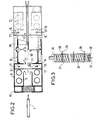
- parts 1 placed on the conveyor 2 pass through a powder coating booth comprising three modules A, B, C: module A serves as an entry airlock, module B is the spray enclosure intended for deposition of powder and contains projection elements 22, and module C is the exit airlock.
- the input and output modules A and C contain vertical cylindrical filters 5, for example four in number.
- a fan 8 placed in a box 12 allows the suction of air through the filters and a cleaning unit (not shown) ensures the regeneration of the filters.
- a fluidization element 3 located at the base of the filters makes it possible to recover the powder which falls from the filters and to return it to a powder reserve 11 situated in the module B of the cabin.
- the latter contains a fluidization unit 9 and a sieve shaker 20.
- the powder deposition elements 22 are of any type, for example electrostatic spray guns.
- the powder deposition elements 22 are connected to injectors 28 which draw the powder directly by means of plungers 10 from the powder reserve 11.
- Each input and output module A, C comprises a reionization compartment D, E contiguous to the central module B.
- These reionization compartments could as well be arranged in the central module B.
- a reionization compartment consists of solid walls 13, 14, 15, 16, leaving a central passage 17 for the parts to be treated. These walls have the effect of constituting obstacles on the path of the powder and, thereby, further confine the powder in the powdering module B by creating a significant pressure drop when passing from the powdering chamber B to the 'filtration chamber A, C. These obstacles force the powder which participates in this transfer to go towards the central axis 18 of the cabin according to the arrows f1, f2 and, thereby, towards the parts which circulate in the cabin.
- the fraction of powder still loaded is redeposited on the parts.
- the reionization compartments D, E further comprise ionizing elements 21, 23, 25, 27 constituted by insulating tubes arranged vertically over the entire height of the cabin. These tubes are pierced with holes 30 crossed by spikes 29 so as to leave a space between the spike and the hole. The points are fixed in the wall of the tube opposite the hole according to a generatrix by a fixing means, such as nailing or the like. The tips 29 are directed towards the center of the cabin, perpendicular to the axis 18 for transferring the parts and pass through a conductive element 31 connected at high voltage by a conductor 32.
- the high voltage source is an electrostatic generator, which may be the same as that used for the spray guns in module B; the tips 29 are thus in contact with the conductive element 31 which bring them to a high potential for carrying out the reionization of the powder.
- the conductive element 31 is constituted by a helical spring suspended in the axis of the tube, between the turns from which the tips 29 have passed.
- the conductive element 31 could also be constituted by a metallic braid.
- the tips are arranged along a generator over the entire height of the tube; one can space for example the points of a distance ranging between 10 and 100 mm.
- the insulating tube 21 is closed at one end by an insulating plug 33, crossed by the supply conductor 32 of the high voltage current so as to avoid electrostatic leaks; its other end is connected to a compressed air supply 34.
- the tips are brought to a high electrical potential via the spring 31 so as to create an ionization of the powder and the compressed air is sent into the tube.
- This air exiting through the holes surrounding the tips has the effect of preventing powder deposits on the tips, which would adversely affect good ionization of the air and the powder present in the compartment.
- the implementation of the invention improves the regularity of the thickness of powder on the parts. Lateral suction through the filters ensures the same powder density over the entire height of the cabin and, consequently, a regular deposition of powder on the parts.
Landscapes
- Electrostatic Spraying Apparatus (AREA)
- Application Of Or Painting With Fluid Materials (AREA)
- Paints Or Removers (AREA)
Claims (12)
Applications Claiming Priority (2)
| Application Number | Priority Date | Filing Date | Title |
|---|---|---|---|
| FR8004906 | 1980-03-05 | ||
| FR8004906A FR2477431A1 (fr) | 1980-03-05 | 1980-03-05 | Procede et dispositif de reionisation de poudre isolante dans une installation de poudrage electrostatique d'objets |
Publications (2)
| Publication Number | Publication Date |
|---|---|
| EP0035246A1 EP0035246A1 (de) | 1981-09-09 |
| EP0035246B1 true EP0035246B1 (de) | 1983-11-23 |
Family
ID=9239328
Family Applications (1)
| Application Number | Title | Priority Date | Filing Date |
|---|---|---|---|
| EP81101408A Expired EP0035246B1 (de) | 1980-03-05 | 1981-02-26 | Verfahren und Vorrichtung zum Wiederionisieren isolierenden Pulvers in Anlagen zur elektrostatischen Pulverbeschichtung |
Country Status (12)
| Country | Link |
|---|---|
| US (1) | US4385079A (de) |
| EP (1) | EP0035246B1 (de) |
| JP (1) | JPS56168852A (de) |
| AR (1) | AR226346A1 (de) |
| BR (1) | BR8101249A (de) |
| DE (1) | DE3161466D1 (de) |
| ES (1) | ES8201444A1 (de) |
| FR (1) | FR2477431A1 (de) |
| GR (1) | GR74474B (de) |
| MX (1) | MX150050A (de) |
| NO (1) | NO810710L (de) |
| YU (1) | YU54481A (de) |
Families Citing this family (2)
| Publication number | Priority date | Publication date | Assignee | Title |
|---|---|---|---|---|
| US6358319B1 (en) | 1999-11-30 | 2002-03-19 | Owens Corning Fiberglass Technology, Inc. | Magnetic method and apparatus for depositing granules onto an asphalt-coated sheet |
| DE10028553A1 (de) * | 2000-06-09 | 2001-12-13 | Itw Gema Ag | Pulversprühbeschichtungskabine |
Citations (6)
| Publication number | Priority date | Publication date | Assignee | Title |
|---|---|---|---|---|
| GB1413964A (en) * | 1972-01-24 | 1975-11-12 | Volstatic Coatings Ltd | Electrostatic coating |
| FR2300625A1 (fr) * | 1975-02-13 | 1976-09-10 | Air Ind | Installation de poudrage electrostatique |
| FR2333585A1 (fr) * | 1975-09-30 | 1977-07-01 | Brennenstuhl Kg Hugo | Procede d'application sur des objets d'une couche de particules pulverulentes ou granuleuses, de flocs ou de fibres |
| GB1530508A (en) * | 1976-05-27 | 1978-11-01 | Volstatic Coatings Ltd | Electrostatic coating equipment |
| FR2403117A1 (fr) * | 1977-09-14 | 1979-04-13 | Volstatic Holdings Ltd | Dispositif pour le depot electrostatique de particules d'un materiau dielectrique de revetement |
| FR2442080A1 (fr) * | 1978-11-21 | 1980-06-20 | Europ Equip Menager | Installation de poudrage electrostatique d'objets |
Family Cites Families (3)
| Publication number | Priority date | Publication date | Assignee | Title |
|---|---|---|---|---|
| US1735494A (en) * | 1925-02-12 | 1929-11-12 | Chapman Electric Neutralizer C | Neutralizer bar |
| FR2182403A5 (de) * | 1972-04-27 | 1973-12-07 | Air Ind | |
| DE2433789A1 (de) * | 1974-07-13 | 1976-01-29 | Bosch Gmbh Robert | Kabine zur pulverbeschichtung |
-
1980
- 1980-03-05 FR FR8004906A patent/FR2477431A1/fr active Granted
-
1981
- 1981-02-26 DE DE8181101408T patent/DE3161466D1/de not_active Expired
- 1981-02-26 EP EP81101408A patent/EP0035246B1/de not_active Expired
- 1981-02-27 BR BR8101249A patent/BR8101249A/pt unknown
- 1981-03-03 NO NO810710A patent/NO810710L/no unknown
- 1981-03-04 MX MX186226A patent/MX150050A/es unknown
- 1981-03-04 ES ES500063A patent/ES8201444A1/es not_active Expired
- 1981-03-04 JP JP3108281A patent/JPS56168852A/ja active Pending
- 1981-03-04 YU YU00544/81A patent/YU54481A/xx unknown
- 1981-04-04 AR AR284515A patent/AR226346A1/es active
- 1981-05-01 US US06/237,968 patent/US4385079A/en not_active Expired - Fee Related
- 1981-10-31 GR GR64287A patent/GR74474B/el unknown
Patent Citations (6)
| Publication number | Priority date | Publication date | Assignee | Title |
|---|---|---|---|---|
| GB1413964A (en) * | 1972-01-24 | 1975-11-12 | Volstatic Coatings Ltd | Electrostatic coating |
| FR2300625A1 (fr) * | 1975-02-13 | 1976-09-10 | Air Ind | Installation de poudrage electrostatique |
| FR2333585A1 (fr) * | 1975-09-30 | 1977-07-01 | Brennenstuhl Kg Hugo | Procede d'application sur des objets d'une couche de particules pulverulentes ou granuleuses, de flocs ou de fibres |
| GB1530508A (en) * | 1976-05-27 | 1978-11-01 | Volstatic Coatings Ltd | Electrostatic coating equipment |
| FR2403117A1 (fr) * | 1977-09-14 | 1979-04-13 | Volstatic Holdings Ltd | Dispositif pour le depot electrostatique de particules d'un materiau dielectrique de revetement |
| FR2442080A1 (fr) * | 1978-11-21 | 1980-06-20 | Europ Equip Menager | Installation de poudrage electrostatique d'objets |
Also Published As
| Publication number | Publication date |
|---|---|
| ES500063A0 (es) | 1981-12-16 |
| FR2477431A1 (fr) | 1981-09-11 |
| JPS56168852A (en) | 1981-12-25 |
| DE3161466D1 (en) | 1983-12-29 |
| NO810710L (no) | 1981-09-07 |
| US4385079A (en) | 1983-05-24 |
| EP0035246A1 (de) | 1981-09-09 |
| MX150050A (es) | 1984-03-05 |
| ES8201444A1 (es) | 1981-12-16 |
| GR74474B (de) | 1984-06-28 |
| AR226346A1 (es) | 1982-06-30 |
| BR8101249A (pt) | 1981-09-08 |
| YU54481A (en) | 1983-06-30 |
| FR2477431B1 (de) | 1984-09-28 |
Similar Documents
| Publication | Publication Date | Title |
|---|---|---|
| US2486877A (en) | Overspray recovery for spray booths | |
| US2334648A (en) | Method of spray-coating articles | |
| US4289504A (en) | Modular gas cleaner and method | |
| CN107427839B (zh) | 用于分离污染物的设备和方法 | |
| US20040065201A1 (en) | Electrostatic dust separator with integrated filter tubing | |
| EP0042111B1 (de) | Verfahren und Vorrichtung zum elektrostatischen Pulverspritzen von Gegenständen in mehreren unterschiedlichen Schichten | |
| FR2620354A2 (fr) | Dispositif de projection electrostatique de produit en poudre | |
| DE2206057A1 (de) | Elektrofilter fuer rauchgase | |
| US4293319A (en) | Electrostatic precipitator apparatus using liquid collection electrodes | |
| US2255677A (en) | Electrical precipitator, especially for minute dust particles | |
| GB1587983A (en) | Electronic air cleaner | |
| US4202674A (en) | Electrostatic gas cleaner | |
| EP0035246B1 (de) | Verfahren und Vorrichtung zum Wiederionisieren isolierenden Pulvers in Anlagen zur elektrostatischen Pulverbeschichtung | |
| WO2012003935A1 (de) | Elektrosortierung mittels koronaentladung | |
| US2579445A (en) | Electrostatic precipitator | |
| KR20170004494A (ko) | 전기집진장치 및 집진방법 | |
| DE2523954A1 (de) | Vorrichtung zur erzeugung eines koronawindes | |
| US2528087A (en) | Apparatus for spray coating | |
| US2306105A (en) | Electrostatic separator for ores and other substances | |
| US4563977A (en) | Electrostatic coating plant | |
| US1444092A (en) | Apparatus for electrical separation of suspended particles from gases | |
| DE60320230T2 (de) | Verfahren zum beschichten eines produktes und vorrichtung | |
| CA1065128A (en) | Method of and apparatus for coating objects with powdered or granular particles, flakes or fibres | |
| US3716024A (en) | A device for spraying an electrified powdered material onto a structure | |
| DE102009030803A1 (de) | Elektrostatischer Abscheider zur Rauchgasreinigung mit einem elektrischen Sperrfeld |
Legal Events
| Date | Code | Title | Description |
|---|---|---|---|
| PUAI | Public reference made under article 153(3) epc to a published international application that has entered the european phase |
Free format text: ORIGINAL CODE: 0009012 |
|
| AK | Designated contracting states |
Designated state(s): BE CH DE FR GB IT LU NL SE |
|
| 17P | Request for examination filed |
Effective date: 19811026 |
|
| ITF | It: translation for a ep patent filed | ||
| GRAA | (expected) grant |
Free format text: ORIGINAL CODE: 0009210 |
|
| AK | Designated contracting states |
Designated state(s): BE CH DE FR GB IT LI LU NL SE |
|
| PGFP | Annual fee paid to national office [announced via postgrant information from national office to epo] |
Ref country code: CH Payment date: 19831227 Year of fee payment: 4 |
|
| REF | Corresponds to: |
Ref document number: 3161466 Country of ref document: DE Date of ref document: 19831229 |
|
| PGFP | Annual fee paid to national office [announced via postgrant information from national office to epo] |
Ref country code: SE Payment date: 19831231 Year of fee payment: 4 |
|
| PGFP | Annual fee paid to national office [announced via postgrant information from national office to epo] |
Ref country code: LU Payment date: 19840112 Year of fee payment: 4 |
|
| PGFP | Annual fee paid to national office [announced via postgrant information from national office to epo] |
Ref country code: FR Payment date: 19840130 Year of fee payment: 4 |
|
| PG25 | Lapsed in a contracting state [announced via postgrant information from national office to epo] |
Ref country code: LU Free format text: LAPSE BECAUSE OF NON-PAYMENT OF DUE FEES Effective date: 19840229 |
|
| PGFP | Annual fee paid to national office [announced via postgrant information from national office to epo] |
Ref country code: BE Payment date: 19840331 Year of fee payment: 4 |
|
| PLBE | No opposition filed within time limit |
Free format text: ORIGINAL CODE: 0009261 |
|
| STAA | Information on the status of an ep patent application or granted ep patent |
Free format text: STATUS: NO OPPOSITION FILED WITHIN TIME LIMIT |
|
| 26N | No opposition filed | ||
| PGFP | Annual fee paid to national office [announced via postgrant information from national office to epo] |
Ref country code: DE Payment date: 19850122 Year of fee payment: 5 |
|
| PGFP | Annual fee paid to national office [announced via postgrant information from national office to epo] |
Ref country code: NL Payment date: 19850125 Year of fee payment: 5 |
|
| PG25 | Lapsed in a contracting state [announced via postgrant information from national office to epo] |
Ref country code: FR Free format text: LAPSE BECAUSE OF NON-PAYMENT OF DUE FEES Effective date: 19851031 |
|
| REG | Reference to a national code |
Ref country code: FR Ref legal event code: ST |
|
| PG25 | Lapsed in a contracting state [announced via postgrant information from national office to epo] |
Ref country code: SE Effective date: 19860227 |
|
| PG25 | Lapsed in a contracting state [announced via postgrant information from national office to epo] |
Ref country code: LI Effective date: 19860228 Ref country code: CH Effective date: 19860228 Ref country code: BE Effective date: 19860228 |
|
| BERE | Be: lapsed |
Owner name: CIE EUROPEENNE POUR L'EQUIPEMENT MENAGER CEPEM Effective date: 19860228 |
|
| PG25 | Lapsed in a contracting state [announced via postgrant information from national office to epo] |
Ref country code: NL Effective date: 19860901 |
|
| GBPC | Gb: european patent ceased through non-payment of renewal fee | ||
| NLV4 | Nl: lapsed or anulled due to non-payment of the annual fee | ||
| REG | Reference to a national code |
Ref country code: CH Ref legal event code: PL |
|
| PG25 | Lapsed in a contracting state [announced via postgrant information from national office to epo] |
Ref country code: DE Effective date: 19861101 |
|
| PG25 | Lapsed in a contracting state [announced via postgrant information from national office to epo] |
Ref country code: GB Effective date: 19881118 |
|
| EUG | Se: european patent has lapsed |
Ref document number: 81101408.3 Effective date: 19861023 |