EP0034744B1 - Beleuchtungsvorrichtung für Anzeigeanordnungen - Google Patents
Beleuchtungsvorrichtung für Anzeigeanordnungen Download PDFInfo
- Publication number
- EP0034744B1 EP0034744B1 EP81100896A EP81100896A EP0034744B1 EP 0034744 B1 EP0034744 B1 EP 0034744B1 EP 81100896 A EP81100896 A EP 81100896A EP 81100896 A EP81100896 A EP 81100896A EP 0034744 B1 EP0034744 B1 EP 0034744B1
- Authority
- EP
- European Patent Office
- Prior art keywords
- display panel
- panel structure
- hollow element
- radiation
- illuminated display
- Prior art date
- Legal status (The legal status is an assumption and is not a legal conclusion. Google has not performed a legal analysis and makes no representation as to the accuracy of the status listed.)
- Expired
Links
Images
Classifications
-
- B—PERFORMING OPERATIONS; TRANSPORTING
- B60—VEHICLES IN GENERAL
- B60Q—ARRANGEMENT OF SIGNALLING OR LIGHTING DEVICES, THE MOUNTING OR SUPPORTING THEREOF OR CIRCUITS THEREFOR, FOR VEHICLES IN GENERAL
- B60Q1/00—Arrangement of optical signalling or lighting devices, the mounting or supporting thereof or circuits therefor
- B60Q1/26—Arrangement of optical signalling or lighting devices, the mounting or supporting thereof or circuits therefor the devices being primarily intended to indicate the vehicle, or parts thereof, or to give signals, to other traffic
- B60Q1/56—Arrangement of optical signalling or lighting devices, the mounting or supporting thereof or circuits therefor the devices being primarily intended to indicate the vehicle, or parts thereof, or to give signals, to other traffic for illuminating registrations or the like, e.g. for licence plates
-
- G—PHYSICS
- G02—OPTICS
- G02B—OPTICAL ELEMENTS, SYSTEMS OR APPARATUS
- G02B6/00—Light guides; Structural details of arrangements comprising light guides and other optical elements, e.g. couplings
- G02B6/0001—Light guides; Structural details of arrangements comprising light guides and other optical elements, e.g. couplings specially adapted for lighting devices or systems
- G02B6/0011—Light guides; Structural details of arrangements comprising light guides and other optical elements, e.g. couplings specially adapted for lighting devices or systems the light guides being planar or of plate-like form
- G02B6/0033—Means for improving the coupling-out of light from the light guide
- G02B6/0035—Means for improving the coupling-out of light from the light guide provided on the surface of the light guide or in the bulk of it
- G02B6/0038—Linear indentations or grooves, e.g. arc-shaped grooves or meandering grooves, extending over the full length or width of the light guide
-
- G—PHYSICS
- G09—EDUCATION; CRYPTOGRAPHY; DISPLAY; ADVERTISING; SEALS
- G09F—DISPLAYING; ADVERTISING; SIGNS; LABELS OR NAME-PLATES; SEALS
- G09F13/00—Illuminated signs; Luminous advertising
- G09F13/18—Edge-illuminated signs
- G09F2013/184—Information to display
- G09F2013/185—Embossed marks
Definitions
- the invention relates to a lighting device for display arrangements in motor vehicle fittings with transparent display fields, the display fields being made recognizable by means of fluoroscopy.
- the illuminated display fields are used in particular to illuminate liquid crystal displays (LCD), which in the future will be used in dashboards instead of analog pointer displays.
- LCD liquid crystal displays
- one or more lamps with or without a reflector are arranged behind the display fields, as a result of which part of the light emitted by the lamp falls on the surfaces to be illuminated.
- the efficiency i. H. the ratio of the transmitted to the generated light, low; there is also often a lack of uniformity of luminance on the surfaces to be illuminated.
- a lighting device for display arrangements which essentially consists of a plate made of glass or transparent plastic, which is surrounded by a reflective frame.
- a miniature incandescent lamp located outside the device injects light into the plate, which is totally reflected by the polished surfaces thereof. Light is emitted to the outside by roughening, i.e. H. Matting certain surface areas.
- Such a lighting device has a high level of uniformity in the light emission, but here too the efficiency is not great, since part of the light is lost due to the feed from the outside. Installation of lamps directly in the transparent plate would increase the luminous flux emitted, but on the other hand it would lead to temperature problems with bright lamps that emit a lot of heat.
- the invention has for its object to achieve a uniform and intensely bright illumination of the display panels.
- the luminance of the fields should be so great that a good reading of the liquid crystal displays illuminated by the device is made possible even in bright, glaring sunlight.
- the lighting device with the features specified in the preamble of the main claim is characterized in that the device consists of a hollow body provided with recesses in the radiation direction, which contains one or more halogen incandescent lamps or discharge lamps, the hollow body has at least 95% radiation-reflecting surface on its inner surfaces , the proportion of the recesses in the total area is equal to or less than 30%, so that multiple reflection occurs in the hollow body, and the overall depth of the hollow body is several times smaller than its other two spatial dimensions.
- the hollow body Due to the hollow body and the multiple reflection, even illumination of all recesses is achieved with just a few light sources. Multiple reflection can only be achieved if the hollow body has special properties. For example, the degree of reflection of all inner surfaces must be at least 95% and the proportion of recesses in the total surface must not exceed 30%.
- halogen incandescent lamps or discharge lamps come into consideration for equipping the lighting device, which, in addition to the luminance required for the illumination of LCD displays, also have sufficiently small dimensions so that the multiple reflection in the hollow body is not disturbed and at the same time a low overall depth of the device is obtained .
- the hollow body also ensures that the maximum ambient temperatures permitted for the lamps (for optimum luminous efficacy) are not exceeded.
- a white, non-yellowing coating known from literature and photometry can be used as the layer which reflects visible light.
- the recesses can be spread with a scattering medium, e.g. B. a cloudy glass pane or a colored film.
- the lighting device can contain lamps which emit UV radiation.
- the hollow body must additionally (on the reflective coating) have a coating which converts the UV radiation into visible radiation on its inner surfaces.
- a coating which converts the UV radiation into visible radiation on its inner surfaces.
- the proportion of the recesses in the total area is advantageously about 10%.
- a significant advantage of the lighting device according to the invention lies in the shallow depth of the hollow body, which thereby saves space and is therefore easy to accommodate in the dashboard. Adequate multiple reflection of the radiation is achieved even with installation depths of the device of less than or equal to 2 cm, so that a uniform light emission takes place through the cutouts.
- the light or radiation sources are arranged within the hollow body in such a way that no direct radiation emerges from the hollow body or that direct radiation only emerges at those points where particularly high luminance levels are required for signaling purposes.
- the light or radiation sources are arranged within the hollow body in such a way that no direct radiation emerges from the hollow body or that direct radiation only emerges at those points where particularly high luminance levels are required for signaling purposes.
- the inner rear wall be.
- the design of the hollow body and the multiple reflection achieved thereby achieve an efficiency which is at least twice as high as in the known arrangements with reflectors.
- the required power consumption of the lamps can be reduced accordingly.
- the hollow body with built-in lamps is advantageously as a unit with devices, for. B. snap locks, which allow assembly without special aids.
- the hollow body 1 is box-shaped and consists of polyester, optionally of sheet metal. Its overall depth a is 20 mm, its width b is 200 mm, its height c is 100 mm. Recesses 3 of different sizes and shapes are provided on its front surface 2 in accordance with the various displays.
- the inner surface of the hollow body is coated in matt white, or the material of the hollow body is strongly colored with white pigments, so that a diffusely reflecting reflectance of 95% or more is achieved, parts of the inner rear wall 4 being structured 5.
- two halogen incandescent lamps of 5 W each are integrated in the hollow body 1 and arranged in such a way that no direct radiation falls on the cutouts.
- the liquid crystal display (not shown) is attached to the front surface 2 and is thus illuminated by the radiation concentrated in the box by multiple reflection through the cutouts.
Landscapes
- Engineering & Computer Science (AREA)
- Mechanical Engineering (AREA)
- Illuminated Signs And Luminous Advertising (AREA)
- Non-Portable Lighting Devices Or Systems Thereof (AREA)
- Planar Illumination Modules (AREA)
- Arrangements Of Lighting Devices For Vehicle Interiors, Mounting And Supporting Thereof, Circuits Therefore (AREA)
Description
- Die Erfindung betrifft eine Beleuchtungsvorrichtung für Anzeigeanordnungen in Kfz-Armaturen mit transparenten Anzeigefeldern, wobei die Anzeigefelder mittels Durchleuchtung erkennbar gemacht werden. Die durchleuchteten Anzeigefelder dienen insbesondere zur Ausleuchtung von Flüssigkristallanzeigen (LCD), die in Zukunft verstärkt anstelle von analogen Zeigeranzeigen in Armaturenbrettern Anwendung finden sollen.
- Üblicherweise sind hinter den Anzeigefeldern eine oder mehrere Lampen mit oder ohne Reflektor angeordnet, wodurch ein Teil des von der Lampe abgestrahlten Lichts auf die zu durchleuchtenden Flächen fällt. Bei einer derartigen Beleuchtung ist der Wirkungsgrad, d. h. das Verhältnis des durchtretenden zum erzeugten Licht, gering; auch mangelt es oft an der Gleichmäßigkeit der Leuchtdichte auf den zu durchleuchtenden Flächen.
- Aus der FR-A-2 317 719 ist eine Beleuchtungsvorrichtung für Anzeigeanordnungen bekannt, die im wesentlichen aus einer Platte aus Glas oder transparentem Kunststoff besteht, die von einem reflektierenden Rahmen eingefaßt ist. Durch eine außerhalb der Vorrichtung befindliche Miniaturglühlampe wird Licht in die Platte eingespeist, das von den polierten Oberflächen derselben totalreflektiert wird. Eine Lichtabgabe nach außen erfolgt durch Aufrauhen, d. h. Mattieren bestimmter Oberflächenbereiche.
- Eine solche Beleuchtungsvorrichtung besitzt eine hohe Gleichmäßigkeit in der Lichtabgabe, aber auch hier ist der Wirkungsgrad nicht groß, da durch die Einspeisung von außen ein Teil des Lichts verlorengeht. Ein Einbau von Lampen direkt in die transparente Platte würde zwar den abgegebenen Lichtstrom erhöhen, andererseits aber bei hellen Lampen mit großer Wärmeabgabe zu Temperaturproblemen führen.
- Der Erfindung liegt die Aufgabe zugrunde, eine gleichmäßige und intensiv helle Durchleuchtung der Anzeigefelder zu erreichen. Die Leuchtdichte der Felder sollte dabei so groß sein, daß auch bei hellem blendenden Sonnenlicht ein gutes Ablesen der mit der Vorrichtung ausgeleuchteten Flüssigkristallanzeigen ermöglicht wird.
- Die Beleuchtungsvorrichtung mit den im Oberbegriff des Hauptanspruchs angegebenen Merkmalen ist dadurch gekennzeichnet, daß die Vorrichtung aus einem in Ausstrahlungsrichtung mit Aussparungen versehenen Hohlkörper besteht, der eine oder mehrere Halogenglühlampen oder Entladungslampen enthält, der Hohlkörper auf seinen inneren Flächen eine mindestens zu 95% strahlungsreflektierende Oberfläche aufweist, der Anteil der Aussparungen an der Gesamtfläche gleich oder kleiner 30% ist, so daß im Hohlkörper Mehrfachreflexion eintritt, und die Bautiefe des Hohlkörpers um ein Mehrfaches kleiner ist als dessen beide andere Raumdimensionen.
- Durch den Hohlkörper und die Mehrfachreflexion wird mit wenigen Lichtquellen eine gleichmäßige Ausleuchtung aller Aussparungen erreicht. Mehrfachreflexion läßt sich aber nur bei Vorliegen besonderer Eigenschaften des Hohlkörpers erreichen. So muß der Reflexionsgrad aller inneren Flächen mindestens 95% betragen und der Anteil der Aussparungen an der Gesamtfläche darf 30% nicht übersteigen. Außerdem kommen für die Bestückung der Beleuchtungsvorrichtung nur Halogenglühlampen bzw. Entladungslampen in Betracht, die neben der für die Ausleuchtung von LCD-Anzeigen notwendigen Leuchtdichte auch genügend kleine Abmessungen besitzen, so daß die Mehrfachreflexion im Hohlkörper nicht gestört und gleichzeitig eine geringe Bautiefe der Vorrichtung erlangt wird. Der Hohlkörper sorgt neben der Mehrfachreflexion auch dafür, daß die für die Lampen höchstzulässigen Umgebungstemperaturen (für eine optimale Lichtausbeute) nicht überschritten werden.
- Als sichtbares Licht reflektierende Schicht kommt ein weißer, nicht vergilbender, aus Literatur und Photometrie bekannter Anstrich in Betracht. Die Aussparungen können mit einem streuenden Medium, z. B. einer Trübglasscheibe oder einer farbigen Folie abgedeckt sein.
- In einer weiteren Ausführungsform kann die Beleuchtungsvorrichtung Lampen enthalten, die UV-Strahlung emittieren. In diesem Fall muß jedoch der Hohlkörper auf seinen inneren Flächen zusätzlich (zur reflektierenden Beschichtung) eine die UV-Strahlung in sichtbare Strahlung umwandelnde Beschichtung aufweisen. Anstelle einer solchen Beschichtung ist es auch möglich, die Aussparungen mit einem Träger abzudecken, auf dem ein die UV-Strahlung in sichtbare Strahlung umwandelnder Leuchtstoff angebracht ist.
- Der Anteil der Aussparungen an der Gesamtfläche beträgt vorteilhaft etwa 10%. Dadurch nimmt die Mehrfachreflexion im Hohlkörper weiter zu und es wird eine noch gleichmäßigere Ausleuchtung der Aussparungen erreicht.
- Bei Kfz-Armaturen ist wegen der zunehmenden Kompaktheit der Autos die Forderung nach geringer Bautiefe ein wesentlicher Gesichtspunkt. Ein bedeutender Vorteil der erfindungsgemäßen Beleuchtungsvorrichtung liegt in der geringen Tiefe des Hohlkörpers, die dadurch sehr raumsparend wird und so leicht im Armaturenbrett unterzubringen ist. Selbst bei Bautiefen der Vorrichtung von kleiner also oder gleich 2 cm wird eine ausreichende Mehrfachreflexion der Strahlung erreicht, so daß eine gleichmäßige Lichtabgabe durch die Aussparungen erfolgt.
- Je nach Verwendungszweck sind die Licht- bzw. Strahlungsquellen innerhalb des Hohlkörpers derart angeordnet, daß keine direkte Strahlung aus dem Hohlkörper austritt oder daß direkte Strahlung nur an denjenigen Stellen austritt, an denen für Signalzwecke besonders hohe Leuchtdichten verlangt werden. Außerdem können z. B. Teile der inneren Rückwand strukturiert sein.
- Durch die Ausbildung des Hohlkörpers und die damit erreichte Mehrfachreflexion wird ein Wirkungsgrad erzielt, der mindestens zweimal so hoch ist wie bei den bekannten Anordnungen mit Reflektoren. Entsprechend kann die benötigte Leistungsaufnahme der Lampen verringert werden. Der Hohlkörper mit eingebauten Lampen wird zweckmäßigerweise als Einheit mit Vorrichtungen, z. B. Schnappverschlüssen, versehen, die eine Montage ohne besondere Hilfsmittel zulassen.
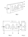
- Ein Ausführungsbeispiel der Erfindung ist in den Fig. 1 bis 3 dargestellt und wird im folgenden näher beschrieben.
- Fig. 1 zeigt eine perspektivische Ansicht des Hohlkörpers,
- Fig. 2 die Rückansicht des Hohlkörpers bei abgenommener Rückwand,
- Fig. 3 den Querschnitt des Hohlkörpers.
- Der Hohlkörper 1 ist kastenförmig ausgebildet und besteht aus Polyester, wahlweise aus Blech. Seine Bautiefe a beträgt 20 mm, seine Breite b 200 mm, seine Höhe c 100 mm. Auf seiner Vorderfläche 2 sind entsprechend den verschiedenen Anzeigen Aussparungen 3 unterschiedlicher Größe und Form vorgesehen. Die Innenfläche des Hohlkörpers ist mattweiß beschichtet, bzw. das Material des Hohlkörpers mit weißen Pigmenten stark eingefärbt, so daß ein diffus reflektierender Reflexionsgrad von 95% oder mehr erreicht wird, wobei Teile der inneren Rückwand 4 strukturiert 5 ausgebildet sind. Als Licht- bzw. Strahlungsquellen 6 sind zwei Halogen-Glühlampen von je 5 W in dem Hohlkörper 1 integriert und derart angeordnet, daß keine direkte Strahlung auf die Aussparungen fällt. Auf die Vorderfläche 2 wird die Flüssigkeitskristall-Anzeige angebracht (nicht dargestellt), die somit von der in dem Kasten durch Mehrfachreflexion konzentrierten Strahlung durch die Aussparungen beleuchtet wird.
Claims (6)
Applications Claiming Priority (2)
| Application Number | Priority Date | Filing Date | Title |
|---|---|---|---|
| DE3006457 | 1980-02-21 | ||
| DE19803006457 DE3006457A1 (de) | 1980-02-21 | 1980-02-21 | Beleuchtungsvorrichtung fuer anzeigeanordnungen |
Publications (2)
| Publication Number | Publication Date |
|---|---|
| EP0034744A1 EP0034744A1 (de) | 1981-09-02 |
| EP0034744B1 true EP0034744B1 (de) | 1985-07-10 |
Family
ID=6095165
Family Applications (1)
| Application Number | Title | Priority Date | Filing Date |
|---|---|---|---|
| EP81100896A Expired EP0034744B1 (de) | 1980-02-21 | 1981-02-09 | Beleuchtungsvorrichtung für Anzeigeanordnungen |
Country Status (3)
| Country | Link |
|---|---|
| EP (1) | EP0034744B1 (de) |
| JP (1) | JPS56135889A (de) |
| DE (2) | DE3006457A1 (de) |
Families Citing this family (5)
| Publication number | Priority date | Publication date | Assignee | Title |
|---|---|---|---|---|
| DE3132967A1 (de) * | 1981-08-20 | 1983-03-03 | Siemens AG, 1000 Berlin und 8000 München | Stand- und parkbeleuchtung an kraftfahrzeugen |
| US4965950A (en) * | 1987-03-23 | 1990-10-30 | Koito Manufacturing Co., Ltd. | Display device for automotive mark plate |
| DE19902774A1 (de) * | 1999-01-25 | 2000-08-10 | Willing Gmbh Dr Ing | Leuchtkörper mit Leuchtdioden für Selbstleuchter und zur Hinterleuchtung von Hinweiselementen |
| CH702730A1 (de) | 2010-02-25 | 2011-08-31 | Weidmann Plastics Tech Ag | Beleuchtbares Bauteil. |
| EP3402695B1 (de) | 2016-01-14 | 2021-06-30 | WEIDPLAS GmbH | Bauteil umfassend ein flächiges dekorelement und ein gehäuse |
Citations (4)
| Publication number | Priority date | Publication date | Assignee | Title |
|---|---|---|---|---|
| DE1655760A1 (de) * | 1967-01-20 | 1970-07-23 | Westfaelische Metall Industrie | Kennzeichenleuchte fuer Kraftfahrzeuge |
| US3780463A (en) * | 1972-05-15 | 1973-12-25 | L Aronoff | Illuminated displays and illuminaries |
| BE864070A (fr) * | 1978-02-17 | 1978-06-16 | Cramer Jean Ch | Dispositif de panneaux lumineux |
| US4141058A (en) * | 1976-05-17 | 1979-02-20 | Copal Company Limited | Light diffusing device |
Family Cites Families (1)
| Publication number | Priority date | Publication date | Assignee | Title |
|---|---|---|---|---|
| FR2317719A1 (fr) * | 1975-07-10 | 1977-02-04 | Voltam Sa | Tableau pour inscriptions pouvant a volonte etre rendues lumineuses |
-
1980
- 1980-02-21 DE DE19803006457 patent/DE3006457A1/de not_active Ceased
-
1981
- 1981-02-09 EP EP81100896A patent/EP0034744B1/de not_active Expired
- 1981-02-09 DE DE8181100896T patent/DE3171287D1/de not_active Expired
- 1981-02-19 JP JP2234681A patent/JPS56135889A/ja active Pending
Patent Citations (4)
| Publication number | Priority date | Publication date | Assignee | Title |
|---|---|---|---|---|
| DE1655760A1 (de) * | 1967-01-20 | 1970-07-23 | Westfaelische Metall Industrie | Kennzeichenleuchte fuer Kraftfahrzeuge |
| US3780463A (en) * | 1972-05-15 | 1973-12-25 | L Aronoff | Illuminated displays and illuminaries |
| US4141058A (en) * | 1976-05-17 | 1979-02-20 | Copal Company Limited | Light diffusing device |
| BE864070A (fr) * | 1978-02-17 | 1978-06-16 | Cramer Jean Ch | Dispositif de panneaux lumineux |
Also Published As
| Publication number | Publication date |
|---|---|
| JPS56135889A (en) | 1981-10-23 |
| DE3171287D1 (en) | 1985-08-14 |
| DE3006457A1 (de) | 1981-08-27 |
| EP0034744A1 (de) | 1981-09-02 |
Similar Documents
| Publication | Publication Date | Title |
|---|---|---|
| DE10258465B4 (de) | Beleuchtungsvorrichtung für ein Kennzeichenschild | |
| DE4228735C2 (de) | Vorrichtung zum Verbessern der Ausleuchtung einer Seitenlichtscheibe | |
| DE3835754A1 (de) | Oberflaechenbeleuchtungseinrichtung | |
| DE2020808B2 (de) | Optisches Bauelement zur Herstellung beleuchtbarer Werbezeichen, Signalvorrichtungen oder dergleichen | |
| EP0949450A2 (de) | Leuchte, insbesondere Heckleuchte, für Kraftfahrzeuge | |
| DE4208922C1 (en) | Flat display background illuminator - has plastics-sealed PCB housing which displays by reflection using diffusing glass in sealing material | |
| DE102005024837B4 (de) | Fahrzeugspiegel mit einem OLED-Leuchtmittel | |
| DE3542292A1 (de) | Leuchte fuer ein kraftfahrzeug | |
| DE102018002721B4 (de) | Beleuchtungsvorrichtung für ein Fahrzeug | |
| DE20100918U1 (de) | Leuchte, insbesondere Signalleuchte, für Kraftfahrzeuge | |
| DE102018214790A1 (de) | Beleuchtungsvorrichtung für ein Kraftfahrzeug | |
| DE10239579A1 (de) | Kraftfahrzeugzierelement | |
| EP0040434B1 (de) | Beleuchtungsvorrichtung für Anzeigeanordnungen | |
| DE10129953A1 (de) | Leuchte für Fahrzeuginnenräume | |
| EP0225977A2 (de) | Beleuchtungseinrichtung | |
| EP0034744A1 (de) | Beleuchtungsvorrichtung für Anzeigeanordnungen | |
| DE4203014A1 (de) | Lichtleiter, z. b. zur beleuchtung von anzuzeigenden zeichen eines kfz-bordcomputers | |
| CH690247A5 (de) | Leuchtkörperaufbau. | |
| DE8013712U1 (de) | Beleuchtungsvorrichtung für Anzeigeanordnungen | |
| EP0602555A2 (de) | Streuscheibe aus milchglasartigem lichthalbdurchlässigen Material, z.B. zur Hintergrundbeleuchtung von LCD-Anzeigen | |
| DE8004606U1 (de) | Beleuchtungsvorrichtung fuer anzeigeanordnungen | |
| EP0050267A2 (de) | Vorrichtung zum Hinterleuchten grossflächiger Anzeigetafeln | |
| DE19533799C2 (de) | Signalleuchte für Fahrzeuge | |
| EP0926704A1 (de) | Flache Signallampe mit dielektrisch behinderter Entladung | |
| DE19818887A1 (de) | Beleuchtungsverfahren für Leuchtschriften |
Legal Events
| Date | Code | Title | Description |
|---|---|---|---|
| PUAI | Public reference made under article 153(3) epc to a published international application that has entered the european phase |
Free format text: ORIGINAL CODE: 0009012 |
|
| AK | Designated contracting states |
Designated state(s): DE FR GB IT |
|
| 17P | Request for examination filed |
Effective date: 19811125 |
|
| ITF | It: translation for a ep patent filed | ||
| GRAA | (expected) grant |
Free format text: ORIGINAL CODE: 0009210 |
|
| AK | Designated contracting states |
Designated state(s): DE FR GB IT |
|
| REF | Corresponds to: |
Ref document number: 3171287 Country of ref document: DE Date of ref document: 19850814 |
|
| ET | Fr: translation filed | ||
| PLBI | Opposition filed |
Free format text: ORIGINAL CODE: 0009260 |
|
| 26 | Opposition filed |
Opponent name: VDO ADOLF SCHINDLING AG Effective date: 19860409 |
|
| RDAG | Patent revoked |
Free format text: ORIGINAL CODE: 0009271 |
|
| STAA | Information on the status of an ep patent application or granted ep patent |
Free format text: STATUS: PATENT REVOKED |
|
| 27W | Patent revoked |
Effective date: 19861121 |
|
| GBPR | Gb: patent revoked under art. 102 of the ep convention designating the uk as contracting state | ||
| REG | Reference to a national code |
Ref country code: FR Ref legal event code: ST |