EP0034312B1 - Quick-connection coupling also connectable under pressure - Google Patents
Quick-connection coupling also connectable under pressure Download PDFInfo
- Publication number
- EP0034312B1 EP0034312B1 EP19810100845 EP81100845A EP0034312B1 EP 0034312 B1 EP0034312 B1 EP 0034312B1 EP 19810100845 EP19810100845 EP 19810100845 EP 81100845 A EP81100845 A EP 81100845A EP 0034312 B1 EP0034312 B1 EP 0034312B1
- Authority
- EP
- European Patent Office
- Prior art keywords
- coupling
- valve
- quick
- valve body
- locking ball
- Prior art date
- Legal status (The legal status is an assumption and is not a legal conclusion. Google has not performed a legal analysis and makes no representation as to the accuracy of the status listed.)
- Expired
Links
Images


Classifications
-
- F—MECHANICAL ENGINEERING; LIGHTING; HEATING; WEAPONS; BLASTING
- F16—ENGINEERING ELEMENTS AND UNITS; GENERAL MEASURES FOR PRODUCING AND MAINTAINING EFFECTIVE FUNCTIONING OF MACHINES OR INSTALLATIONS; THERMAL INSULATION IN GENERAL
- F16L—PIPES; JOINTS OR FITTINGS FOR PIPES; SUPPORTS FOR PIPES, CABLES OR PROTECTIVE TUBING; MEANS FOR THERMAL INSULATION IN GENERAL
- F16L37/00—Couplings of the quick-acting type
- F16L37/22—Couplings of the quick-acting type in which the connection is maintained by means of balls, rollers or helical springs under radial pressure between the parts
- F16L37/23—Couplings of the quick-acting type in which the connection is maintained by means of balls, rollers or helical springs under radial pressure between the parts by means of balls
-
- F—MECHANICAL ENGINEERING; LIGHTING; HEATING; WEAPONS; BLASTING
- F16—ENGINEERING ELEMENTS AND UNITS; GENERAL MEASURES FOR PRODUCING AND MAINTAINING EFFECTIVE FUNCTIONING OF MACHINES OR INSTALLATIONS; THERMAL INSULATION IN GENERAL
- F16L—PIPES; JOINTS OR FITTINGS FOR PIPES; SUPPORTS FOR PIPES, CABLES OR PROTECTIVE TUBING; MEANS FOR THERMAL INSULATION IN GENERAL
- F16L37/00—Couplings of the quick-acting type
- F16L37/28—Couplings of the quick-acting type with fluid cut-off means
- F16L37/30—Couplings of the quick-acting type with fluid cut-off means with fluid cut-off means in each of two pipe-end fittings
- F16L37/32—Couplings of the quick-acting type with fluid cut-off means with fluid cut-off means in each of two pipe-end fittings at least one of two lift valves being opened automatically when the coupling is applied
-
- Y—GENERAL TAGGING OF NEW TECHNOLOGICAL DEVELOPMENTS; GENERAL TAGGING OF CROSS-SECTIONAL TECHNOLOGIES SPANNING OVER SEVERAL SECTIONS OF THE IPC; TECHNICAL SUBJECTS COVERED BY FORMER USPC CROSS-REFERENCE ART COLLECTIONS [XRACs] AND DIGESTS
- Y10—TECHNICAL SUBJECTS COVERED BY FORMER USPC
- Y10T—TECHNICAL SUBJECTS COVERED BY FORMER US CLASSIFICATION
- Y10T137/00—Fluid handling
- Y10T137/8158—With indicator, register, recorder, alarm or inspection means
- Y10T137/8326—Fluid pressure responsive indicator, recorder or alarm
-
- Y—GENERAL TAGGING OF NEW TECHNOLOGICAL DEVELOPMENTS; GENERAL TAGGING OF CROSS-SECTIONAL TECHNOLOGIES SPANNING OVER SEVERAL SECTIONS OF THE IPC; TECHNICAL SUBJECTS COVERED BY FORMER USPC CROSS-REFERENCE ART COLLECTIONS [XRACs] AND DIGESTS
- Y10—TECHNICAL SUBJECTS COVERED BY FORMER USPC
- Y10T—TECHNICAL SUBJECTS COVERED BY FORMER US CLASSIFICATION
- Y10T137/00—Fluid handling
- Y10T137/8593—Systems
- Y10T137/87917—Flow path with serial valves and/or closures
- Y10T137/87925—Separable flow path section, valve or closure in each
- Y10T137/87965—Valve- or closure-operated by coupling motion
-
- Y—GENERAL TAGGING OF NEW TECHNOLOGICAL DEVELOPMENTS; GENERAL TAGGING OF CROSS-SECTIONAL TECHNOLOGIES SPANNING OVER SEVERAL SECTIONS OF THE IPC; TECHNICAL SUBJECTS COVERED BY FORMER USPC CROSS-REFERENCE ART COLLECTIONS [XRACs] AND DIGESTS
- Y10—TECHNICAL SUBJECTS COVERED BY FORMER USPC
- Y10T—TECHNICAL SUBJECTS COVERED BY FORMER US CLASSIFICATION
- Y10T137/00—Fluid handling
- Y10T137/8593—Systems
- Y10T137/87917—Flow path with serial valves and/or closures
- Y10T137/87925—Separable flow path section, valve or closure in each
- Y10T137/87973—Coupling interlocked with valve, or closure or actuator
Definitions
- the invention relates to a quick-release coupling which can also be coupled under pressure and has the features listed in the preamble of claim 1.
- a coupling can be used either as a normal coupling, as a breakaway coupling or as a pipe breakaway coupling.
- Such a quick release coupling is known from DE-B-2 712 117 or also from US-A-3 791 411.
- it is the valve body of the plug valve which is mounted in the star body so that it can only be displaced by the simple opening stroke, the star body itself forming a fixed stop for limiting the simple valve stroke of the valve body.
- the star body can be adjusted relative to the coupling body of the plug valve with the aid of a thread.
- the sleeve valve of DE-B-2 712117 has a valve body which is acted upon in the closing direction by a closing spring, but which is generally mounted displaceably in the coupling body of the sleeve valve by double the simple valve stroke.
- the flow guidance is comparatively better solved, so that in particular a comparable pressure loss due to flow deflection is not to be expected, but here too the blocking means is housed disadvantageously within the flow cross-section of the socket valve and between it Star body and the valve body arranged and effective.
- the locking means also acts eccentrically on the valve body due to its radial arrangement and placement on a small diameter, which is not optimal with regard to the transfer of pressure forces from the flow medium to the valve body and with regard to the support of these forces.
- the individual parts of the locking means can also be formed only in a limited size, which is also disadvantageous.
- a quick release coupling in which the star body of the sleeve valve is fixed in a sleeve coaxial with the coupling body and is axially displaceably mounted with it in the coupling body at least in accordance with the simple valve stroke.
- the sleeve which carries the seat for the valve body is of stepped construction and is acted upon by the force of a spring which is supported on the coupling body in the closing direction of the valve body.
- the stepped design of the sleeve results in an active surface, so that when the fluid pressure begins, the sleeve is loaded by a hydraulic force on the active surface in addition to the mechanical force of the spring.
- locking which is understood as mechanical locking by means of a stop, does not take place here.
- the invention has for its object to develop a quick-release coupling of the type described above that can be coupled so that there are no problems with regard to the accommodation of the locking means designed as a removable and engaging stop for locking the valve body provided for the double valve lift in the simple Stroke corresponding position. Even with small nominal widths, it should be possible to keep the diameter of the coupling halves correspondingly small.
- the new quick-release coupling is thus fundamentally detached from the prior art in that the blocking means is not accommodated and arranged inside, ie within the flow cross-section, but outside the same and thus on a larger diameter. This allows the individual parts of a further locking ball lock to be housed in a reasonable size in connection with the removable and engaging stop, with the particular advantage that a symmetrical force application or force support around the longitudinal axis of the coupling halves can be easily realized.
- the new quick-release coupling has the further advantage that after the coupling process has ended, when the sliding sleeve has reached its proper end position, the two valve bodies are locked even when two unpressurized lines have been coupled together ; in such a case, the line connection can be shut off in such a case in the event of pressure fluctuations, that is to say the passage can be interrupted before locking is achieved. Without a one-off barrier, locking will not be achieved.
- the star body itself can be slidably mounted directly in the coupling body, at least one stroke corresponding to the simple valve stroke having to be provided here.
- the enlargement of this stroke does not harm in any case, but only has a positive effect, especially with regard to the combination options with different plug valves.
- a separate sleeve is provided between the star body and the coupling body, which carries the valve seat, on which the star body is supported and between which and the coupling body the further locking ball lock is provided. It is also possible that this sleeve is not currently carrying the valve seat. In all these cases, however, the further locking ball lock, which can be actuated from the outside, is arranged on a relatively large diameter.
- the star body or the sleeve with the greater stroke than the simple valve stroke of its valve body is slidably mounted in the coupling body, it is ensured that different plug valves can be coupled with one and the same socket valve and vice versa, and tolerance differences in the processing of the individual parts are not disadvantageous impact.
- the stop that can be disengaged and engaged can be designed to be adjustable in order to eliminate tolerance differences in the axial direction and to be able to adjust the stop so that the associated valve body can be locked without play in the coupled position.
- Claim 3 shows one possible implementation.
- a sliding sleeve which is displaceably mounted on the circumference of the coupling body against spring pressure, which preferably allows the balls to be released in both actuating devices.
- the design of the known sliding sleeve which already has evading grooves in known directions known as train-push-couplings in connection with a locking cam, offers itself as a model. But it can also be provided a common sliding sleeve according to claim 4, so that there is easier operation. It is particularly important that the locking means is not yet moved back into its disengagement position allowing the double valve lift when the coupling halves are uncoupled, but that the disengagement position is released for the coupling halves when the locking ball lock is released.
- the common sliding sleeve can each have a locking cam and adjoining at least one-sided escape grooves for the balls of the two locking ball locks. This makes it possible to have already closed the locking ball lock for the two coupling halves, that is to say to have transferred them to the locked position without the further locking ball locking device having already been locked. However, this inevitably means that the sliding sleeve is not yet in its end position indicating the correct locking of both locking ball locks relative to the coupling body. It is therefore visible from the outside that only a locking ball lock is effective.
- the coupling sleeve can have markings. When training as a push-pull coupling, the number of markings increases twice.
- the locking cam is axially displaceably mounted on the common sliding sleeve and is spring-loaded in the central position of its stroke.
- the locking cam of the second locking ball lock is thus made movable relative to the common sliding sleeve, wherein it is axially displaceable to a limited extent and is spring-loaded in the central position, so that it strives to always assume this central position.
- the locking cam is not prevented from shifting axially laterally when the corresponding forces act on it.
- the spring force and the axially movable locking cam can be skillfully used for this purpose , so that it exerts a relative movement even if the common sliding sleeve is prevented from moving by the force exerted radially by the balls of the first ball ratchet.
- the locking cam is particularly advantageous for the locking cam to be axially displaceable as a ring in a recess of the common sliding sleeve formed by the escape grooves, with two approximately equally strong springs being mounted to the right and left of the annular locking cam.
- the springs are expediently preloaded accordingly, the ring-shaped locking cam being able to have bevels on the inside for the balls. This makes it easier to close the second locking ball lock.
- the two springs are arranged outside the radial range of movement of the balls, so that they are not clamped by the balls and can transmit their axially directed force to the annular locking cams in any position.
- Each quick release coupling basically consists of a plug valve 1 and a sleeve valve 2. Only a single embodiment is shown of the plug valve 1, while the sleeve valve shows a first embodiment in the upper half of the drawing and a second embodiment in all figures in the lower half of the drawing.
- the plug valve 1 consists essentially of a coupling body 3 with a seat 4.
- the star body 5 which has three protruding arms 6 distributed over the circumference, is mounted with the aid of the securing ring 7.
- the star body 5 is sleeve-shaped and has a central bore 8 in which the stem 9 of a valve body 10 is slidably guided.
- the valve body 10 forms with the seat 4 of the coupling body 3 a check valve 10, 4, which closes the line in question, which is connected to the plug valve 1, as can be seen.
- the valve body 10 is pressed against the seat 4 by means of a closing spring 11, which on the other hand holds the star body 5 in contact with the locking ring 7.
- the valve body 10 projects beyond the end wall 12 of the plug valve 1 by the dimension a '.
- the adjusting screw 13 is also supported by means of a thread, the front end of which forms a stop 14 for the end of the shaft 9 or the valve body 10.
- the adjusting screw 13 is set in the star body 5 by means of the thread so that the stop 14 is at a distance a 'from the end of the stem 9 of the valve body 10.
- the valve body 10 can thus cover the valve stroke a 'between its open position and its closed position.
- the coupling body 3 has a circumferential locking groove 15 at the point shown, which with a locking ball lock to be described later for locking the plug valve 1 with the sleeve valve 2 in the coupled position and for releasing the two Parts 1, 2 cooperate in the uncoupled position.
- the sleeve valve 2 now also has a coupling body 16 which is screwed onto a connecting piece 17, a seal 18 sealing the interior in a pressure-tight manner.
- a seat sleeve 19 is slidably mounted in the coupling body 16, in which a star body 20 is mounted with the aid of the locking ring 21.
- the seat sleeve 19 carries the seat 22.
- the star body 20 is slidably mounted directly in the coupling body 16.
- the star body 20 in the second embodiment has a sliding sleeve 23.
- the star body 20 has, for example, three radially projecting arms 24, between which the flow can take place over the circumference.
- the seat 22 is formed by the coupling body 16.
- a bore 25 is also provided on the sleeve valve 2 in the center of the star body 20, which bores the shaft 26 of the valve body 27.
- the valve body 27 forms with the seat 22 the check valve 22, 27 of the socket valve 2.
- the front end of the valve body 27 protrudes beyond the end plane 28 by the dimension a.
- an adjusting screw 29 is arranged so as to be adjustable and adjustable with the aid of a thread, the front end of which forms a stop 30 for the rear end of the shaft 26 or the valve body 27.
- the adjusting screw 29 is set so that the valve body 27 can perform the valve stroke a when opening before it strikes the stop 30 with its shaft 26.
- the closing spring 31 is switched on between the star body 20 and the valve body 27.
- valve stroke a of the sleeve valve 2 corresponds approximately to the valve stroke a 'of the plug valve 1. Both valve strokes a and a' differ only by tolerances due to the manufacturing process. Basically, the same level is aimed at and set during production.
- the star body 20 is mounted in the upper embodiment via the seat sleeve 19 or with this and in the lower embodiment directly via its sliding sleeve 23 in the coupling body 16, the two seals 32 and 33 being arranged for sealing purposes. In both cases it is achieved that the star body 20 is axially displaceable by the dimension b relative to the coupling body 16.
- the dimension b is at least the same size as the valve stroke a '(or a), but has been chosen larger in order to facilitate production. In any case, this makes it possible for the valve body 27 of the sleeve valve 2 to be mounted displaceably overall by twice the valve stroke 2a, while the valve body 10 of the plug valve 1 can only be displaced by the simple valve stroke a '.
- the star body 20 with its sliding sleeve 23 or the separate seat sleeve 19 are supported by a compression spring 34 on the connector 17 or on a shoulder of the coupling body 16.
- the force of the compression spring 34 is selected to be greater than the force of the closing spring 31, so that a clear chronological sequence of the relative movements is defined in this way.
- the coupling body 16 is surrounded by a sliding sleeve 35, which is designed here as a common sliding sleeve and serves to actuate two different locking ball locks, as will be explained in the following.
- the sliding sleeve 35 is slidably mounted on the coupling body 16 with the aid of the spring 36 in both directions.
- the entire quick release coupling is designed as a so-called pull-push coupling, i. H. the sliding sleeve 35 can be moved in both directions with respect to the coupling body for the purpose of releasing the two locking ball locks.
- the sliding sleeve 35 has a relatively wide locking cam 37, to which two escape grooves 38 and 39 connect in both directions.
- the coupling body 16 has, in a manner known per se, a series of radial openings 40 in which balls 41 are mounted.
- the locking cam 37 forms in connection with the evasion grooves 38, 39, the balls 41 and the locking groove 15 of the plug valve 1, a first locking ball lock 15, 37, 38, 39, 40, 41, which is used to lock the plug valve 1 and sleeve valve 2 in the coupled position or to release the two parts in the uncoupled position. Locking ball locks of this type are known per se and therefore do not require any further description.
- the further seal 42 is accommodated on the coupling body 16 of the socket valve 2.
- the common sliding sleeve 35 also serves to actuate a second locking ball lock.
- the sliding sleeve 35 has a further circumferential locking cam 43, which is comparatively less wide than the locking cam 37.
- a circumferentially annular locking cam 43 is axially displaceably mounted on the sliding sleeve 35 and can be made comparatively less wide than the locking cam 37.
- the locking cam 43 there are in turn escape grooves 44 and 45 on both sides.
- the coupling body 16 (FIGS. 1 to 8) has a plurality of openings 46 arranged around the circumference for receiving the balls 47.
- a circumferential locking groove 48 is in the seat sleeve 19 or in the sliding sleeve 23 of the star body 20 incorporated outside.
- the locking cam 43 forms in connection with the evading grooves 44, 45, the openings 46 in the coupling body 16, the balls 47 and the locking groove 48, the second locking ball lock 43 to 48, which for locking the star body 20 relative to the coupling body 16 or in its other position Release serves.
- the second locking ball lock 43 to 48 forms an engaging and disengaging stop for limiting or releasing the axial movement of the valve body 27.
- valve body 27 can cover a maximum of the simple valve lift a, if a corresponding force is exerted on the tip of the valve body 27, which leads to overcoming the force of the closing spring 31. If, on the other hand, the second locking ball lock 43 to 48 is disengaged or released, as shown, for example, in FIG. 2, the valve body 27 can not only perform the single valve lift a, but can also cover the double valve lift relative to the end plane 28, which is the sum of the two of the individual valve strokes a + a'z2-a.
- the evasion grooves 44 and 45 form an axially continuous recess in which the annular locking cam 43 is axially displaceably supported relative to the common sliding sleeve 35 and acted upon by two springs 54 and 55 in the direction of the axial central position of its stroke is.
- the pressure medium flows through the spaces between the arms 24 via the open check valve 22, 27 against the valve body 10 and additionally loads it against the force of the closing spring 11 and the pressure locked there.
- the pressure of the compression spring 34 acts on the valve body 10 via the valve body 27, so that an overall opening movement of the check valve 10, 4 takes place in all cases or at a corresponding pressure level, so that the pressure compensation is established.
- this pressure also acts on the rear of the valve body 27, this movement being supported by the force of the compression spring 34.
- valve body 27 again moves to the right by the simple valve stroke a ', the valve body 10 being carried along and of course also performing the simple valve stroke a' until its stem 9 comes to rest on the fixed stop 14.
- This position of the parts is shown in Fig. 4.
- the sliding sleeve 23 of the star body 20 also moves so far to the right that the locking groove 48 is in the region of the balls 47 arrives, so that in addition to the first locking ball lock, the second ball lock 43 to 48 can now also close.
- This closed position is made possible in the embodiments of FIGS. 5 to 8 by the axially displaceable mounting of the locking cam 43 and the force of the spring 54.
- Both the first locking ball lock 15, 37 to 41 and the second locking ball lock 43 to 48 are then in the locked position, as shown in FIGS. 4 and 8, respectively.
- a further marking 52 (FIG. 4) on the outer circumference of the coupling body 16 is thus visible relative to the end of the sliding sleeve 35 when it has shifted into the end position shown in FIG.
- the outer circumference of the sliding sleeve 35 in connection with a recess 56 indicates that the locking cam 43 has moved according to arrow 53 into the end position shown in FIG. 8.
- the markings 51 and 52 reliably indicate that both locking ball locks are locked. This means that the stop 30 is also engaged again, ie it is effective.
- the two valve bodies 10 and 27 are thus in a firmly locked position between the stops 14 and 30, so that pressure fluctuations in the pressure medium cannot lead to any significant displacement of the valve bodies 10, 27 in parts 1, 2 of the quick-action coupling.
- the end face 12 of the plug valve 1 and the end face 28 of the socket valve 2 assume a common end face level in the coupled position, as shown in FIG. 4.
- the sliding sleeve 35 is actuated from the position according to FIGS. 4 to 8 either in the direction of the arrows 49 or in the opposite direction, so that the two locking ball locks 15, 37 to 41 and 43 to 48 are unlocked.
- the plug valve 1 is pushed out of the sleeve valve 2, with both check valves 20, 4 and 22, 27 moving into the closed position, as shown in FIGS. 1 and 5.
- FIGS. 1 to 4 or 5 to 8 in the upper half has an analogous mode of operation, in which case the star body 20 is displaced together with the seat sleeve 19.
- the drawings show the various intermediate positions provided that the compression spring 34 is designed to be stronger than the closing spring 31. On the other hand, if the closing spring 31 is made stronger than the compression spring 34, this would result in a somewhat different mode of operation. In the intermediate position according to FIGS. 2 and 6, there would then be the possibly desired advantage that both check valves 4, 10 and 22, 27 would be closed in this intermediate position.
- the quick-release coupling can of course also be coupled and uncoupled if neither of the two lines respectively connected to the plug valve 2 and the socket valve 2 are under pressure during the coupling or uncoupling process.
- the springs 11, 31, 34 depending on the coordination of the springs 11, 31, 34, a different sequence of movements of the individual valve bodies relative to the coupling bodies 3 and 16 occurs.
- the valve body 10 will perform the simple valve lift a 'during the coupling process without pressure, while the valve body 27 does the same simple valve lift a executes, so that the open position of the two check valves 4, 10 and 22, 27 is reached according to FIG. 4. But even in this case the locking position is reached immediately when the coupling process is finished and the sliding sleeve has reached its end position. The passage through the quick release coupling is open and remains open because the valve bodies are locked before the pressure source is switched on. A one-time closing operation in the sense of a double lifting movement is no longer necessary to reach the locking position.
Description
Die Erfindung bezieht sich auf eine auch unter Druck kuppelbare Schnellverschlusskupplung mit den im Oberbegriff des Anspruches 1 aufgeführten Merkmalen. Eine solche Kupplung kann entweder als normale Kupplung, als Abreisskupplung oder als Rohr-Abreisskupplung eingesetzt werden.The invention relates to a quick-release coupling which can also be coupled under pressure and has the features listed in the preamble of
Eine derartige Schnellverschlusskupplung ist aus der DE-B-2 712 117 oder auch der US-A-3 791 411 bekannt. In aller Regel ist es der Ventilkörper des Steckerventils, der nur um den einfachen Öffnungshub verschiebbar in dem Sternkörper gelagert ist, wobei der Sternkörper selbst einen festen Anschlag für die Begrenzung des einfachen Ventilhubes des Ventilkörpers bildet. Gemäss der US-A-3 791 411 kann der Sternkörper mit Hilfe eines Gewindes relativ zum Kupplungskörper des Steckerventils eingestellt werden. Das Muffenventil der DE-B-2 712117 besitzt einen in Schliessrichtung über eine Schliessfeder beaufschlagten Ventilkörper, der jedoch in aller Regel um das Doppelte des einfachen Ventilhubes verschiebbar in dem Kupplungskörper des Muffenventils gelagert ist.Such a quick release coupling is known from DE-B-2 712 117 or also from US-A-3 791 411. As a rule, it is the valve body of the plug valve which is mounted in the star body so that it can only be displaced by the simple opening stroke, the star body itself forming a fixed stop for limiting the simple valve stroke of the valve body. According to US Pat. No. 3,791,411, the star body can be adjusted relative to the coupling body of the plug valve with the aid of a thread. The sleeve valve of DE-B-2 712117 has a valve body which is acted upon in the closing direction by a closing spring, but which is generally mounted displaceably in the coupling body of the sleeve valve by double the simple valve stroke.
Bei der Konstruktion nach der DE-B-2712117 ist zwar die Strömungsführung vergleichsweise besser gelöst, so dass hier insbesondere ein vergleichbarer Druckverlust infolge Strömungsumlenkung nicht zu erwarten ist, jedoch ist auch hier in nachteiliger Weise das Sperrmittel innerhalb des Durchströmquerschnittes des Muffenventils untergebracht und zwischen dem Sternkörper und dem Ventilkörper angeordnet und wirksam. Dies bedeutet, dass auch hier das Sperrmittel infolge seiner radialen Anordnung und Unterbringung auf kleinem Durchmesser ebenfalls exzentrisch an dem Ventilkörper angreift, was hinsichtlich der Übertragung von Druckkräften von dem Strömungsmedium her auf den Ventilkörper und hinsichtlich der Abstützung dieser Kräfte nicht optimal ist. Auch können die Einzelteile des Sperrmittels nur in begrenzter Grösse ausgebildet werden, was ebenfalls nachteilig ist. Da die Sternkörper des Muffenventils und des Steckerventils nicht in ihrer relativen Lage einstellbar ausgebildet sind, ist eine äusserst präzise toleranzmässige Bearbeitung der Teile erforderlich, um eine ordnungsgemässe Wirkung des Sperrmittels zu erreichen, d.h. einen Anschlag auch dann einzurücken, wenn verlässlich der einfache Ventilhub zurückgelegt ist. Beim Kuppeln unterschiedlicher Stecker mit einer Muffe bzw. umgekehrt können daher die Teile auch in solchen Toleranzen gerade zufällig kombiniert werden, dass die Wirkung des Sperrmittels überhaupt nicht eintritt. Auch bei dieser Konstruktion tritt der weitere Nachteil auf, dass von aussen nicht erkennbar ist, ob das Sperrmittel ordnungsgemäss seine Funktion erfüllt, also beispielsweise die eingesetzte Feder des Sperrmittels nicht gebrochen ist. Bei kleinen Nennweiten baut auch diese bekannte Kupplung im Durchmesser relativ gross, weil das Sperrmittel im Innern eine entsprechende Minimalausdehnung erfordert.In the construction according to DE-B-2712117, the flow guidance is comparatively better solved, so that in particular a comparable pressure loss due to flow deflection is not to be expected, but here too the blocking means is housed disadvantageously within the flow cross-section of the socket valve and between it Star body and the valve body arranged and effective. This means that the locking means also acts eccentrically on the valve body due to its radial arrangement and placement on a small diameter, which is not optimal with regard to the transfer of pressure forces from the flow medium to the valve body and with regard to the support of these forces. The individual parts of the locking means can also be formed only in a limited size, which is also disadvantageous. Since the star bodies of the socket valve and the plug valve are not designed to be adjustable in their relative position, extremely precise tolerance-based machining of the parts is necessary in order to achieve a correct effect of the locking means, i.e. to engage a stop even when the simple valve stroke has been reliably completed. When coupling different plugs with a sleeve or vice versa, the parts can therefore be combined in such tolerances just by chance that the blocking agent does not work at all. This construction also has the further disadvantage that it cannot be seen from the outside whether the locking means is functioning properly, for example the spring of the locking means used is not broken. In the case of small nominal diameters, this known coupling also has a relatively large diameter because the locking means requires a corresponding minimum expansion inside.
Um dem Nachteil des exzentrischen Kraftangriffes des Sperrmittels an dem Ventilkörper zumindest teilweise zu begegnen, ist es gemäss DE-A-2 715 417 bekannt, ein Teil des Sperrmittels, nämlich ein Schaufelgitter, symmetrisch zur Längsachse der Kupplung auszubilden und anzuordnen, welches dann aber wieder in exzentrischer Weise in Vertiefungen des Schaftes des Ventilkörpers eingreift, wenn es in der gekuppelten Stellung von der dann einsetzenden Strömung betätigt wird. Bei dieser Konstruktion ist das Sperrmittel unmittelbar zwischen dem Kupplungskörper und dem Schaft des Ventilkörpers, also im Innern angeordnet, so dass von aussen nicht erkennbar ist, ob das Sperrmittel in entsprechender Position ordnungsgemäss verriegelt oder nicht verriegelt ist.In order to at least partially counteract the disadvantage of the eccentric force application of the locking means on the valve body, it is known according to DE-A-2 715 417 to design and arrange part of the locking means, namely a vane grate, symmetrically to the longitudinal axis of the coupling, but this again engages in an eccentric manner in depressions of the stem of the valve body when it is actuated in the coupled position by the flow then starting. In this construction, the locking means is arranged directly between the coupling body and the stem of the valve body, that is to say inside, so that it cannot be seen from the outside whether the locking means is properly locked or not locked in the appropriate position.
Aus der US-A-3 500 859 ist eine Schnellverschlusskupplung bekannt, bei der der Sternkörper des Muffenventils in einer zum Kupplungskörper koaxialen Hülse festgelegt und mit dieser in den Kupplungskörper mindestens entsprechend dem einfachen Ventilhub axial verschieblich gelagert ist. Die Hülse, die den Sitz für den Ventilkörper trägt, ist gestuft ausgebildet und wird von der Kraft einer sich am Kupplungskörper abstützenden Feder in Schliessrichtung des Ventilkörpers beaufschlagt. Durch die gestufte Ausbildung der Hülse ergibt sich eine Wirkfläche, so dass bei einsetzendem Strömungsmitteldruck die Hülse zusätzlich zu der mechanischen Kraft der Feder von einer hydraulischen Kraft auf der Wirkfläche belastet ist. Eine Verriegelung, die als mechanische Verriegelung mittels eines Anschlages verstanden wird, findet hier jedoch nicht statt.From US-A-3 500 859 a quick release coupling is known in which the star body of the sleeve valve is fixed in a sleeve coaxial with the coupling body and is axially displaceably mounted with it in the coupling body at least in accordance with the simple valve stroke. The sleeve which carries the seat for the valve body is of stepped construction and is acted upon by the force of a spring which is supported on the coupling body in the closing direction of the valve body. The stepped design of the sleeve results in an active surface, so that when the fluid pressure begins, the sleeve is loaded by a hydraulic force on the active surface in addition to the mechanical force of the spring. However, locking, which is understood as mechanical locking by means of a stop, does not take place here.
Der Erfindung liegt die Aufgabe zugrunde, eine auch unter Druck kuppelbare Schnellverschlusskupplung der eingangs beschriebenen Art so weiterzubilden, dass sich keine Probleme ergeben hinsichtlich der Unterbringung des als aus- und einrückbarer Anschlag ausgebildeten Sperrmittels zur Verriegelung des für den doppelten Ventilhub vorgesehenen Ventilkörpers in der dem einfachen Hub entsprechenden Stellung. Auch bei kleinen Nennweiten soll es möglich sein, den Durchmesser der Kupplungshälften entsprechend klein zu halten.The invention has for its object to develop a quick-release coupling of the type described above that can be coupled so that there are no problems with regard to the accommodation of the locking means designed as a removable and engaging stop for locking the valve body provided for the double valve lift in the simple Stroke corresponding position. Even with small nominal widths, it should be possible to keep the diameter of the coupling halves correspondingly small.
Dies wird durch die im Anspruch 1 niedergelegte Erfindung erreicht. Die neue Schnellverschlusskupplung löst sich somit grundsätzlich vom Stand der Technik, indem das Sperrmittel nicht im Innern, also innerhalb des Strömungsquerschnittes, sondern ausserhalb desselben und damit auf grösserem Durchmesser untergebracht und angeordnet wird. Damit können die Einzelteile einer weiteren Sperrkugelverriegelung in Verbindung mit dem aus- und einrückbaren Anschlag in einer vernünftigen Grösse konstruktiv untergebracht werden, wobei der besondere Vorteil entsteht, dass ein symmetrischer Kraftangriff bzw. Kraftabstützung um die Längsachse der Kupplungshälften herum ohne weiteres verwirklicht werden kann. Da die weitere Sperrkugelverriegelung nicht mehr im Innern, sondern in Verbindung mit dem Kupplungskörper ausserhalb des Strömungsquerschnittes angeordnet wird, besteht der weitere Vorteil, dass bei entsprechender Ausbildung ohne weiteres aussen erkennbar gemacht werden kann, ob eine ordnungsgemäss verriegelte Stellung nach dem Kuppeln der Kupplungshälften in bezug auf den aus- und einrückbaren Anschlag eingenommen wird oder nicht. An der Kupplung ist in gekuppelter Stellung aussen sichtbar, dass die Offenstellung des Ventilkörpers, der den doppelten Ventilhub besitzt, ordnungsgemäss verriegelt ist. Dies stellt eine erhebliche Steigerung der Sicherheit beim Gebrauch dar. Die neue Schnellverschlusskupplung besitzt den weiteren Vorteil, dass nach Beendigung des Kuppelvorganges, wenn die Schiebehülse ihre ordnungsgemässe Endposition erreicht hat, die beiden Ventilkörper auch dann verriegelt sind, wenn zwei drucklose Leitungen miteinander gekuppelt worden sind; beim Stand der Technik kann in einem solchen Falle bei Druckschwankungen die Leitungsverbindung einmal abgesperrt, also der Durchgang unterbrochen werden, bevor eine Verriegelung erreicht wird. Ohne einmalige Absperrung wird eine Verriegelung nicht erreicht.This is achieved by the invention as set out in
Der Sternkörper kann selbst und unmittelbar in dem Kupplungskörper verschiebbar gelagert sein, wobei hier mindestens ein Hub entsprechend dem einfachen Ventilhub vorgesehen sein muss. Die Vergrösserung dieses Hubes schadet jedoch in keinem Falle, sondern wirkt sich, insbesondere im Hinblick auf die Kombinationsmöglichkeiten mit verschiedenen Steckerventilen, nur positiv aus. Es ist aber auch möglich, dass zwischen Sternkörper und Kupplungskörper eine gesonderte Hülse vorgesehen ist, die den Ventilsitz trägt, an der der Sternkörper abgestützt ist und zwischen der und dem Kupplungskörper die weitere Sperrkugelverriegelung vorgesehen ist. Es ist auch möglich, dass diese Hülse gerade nicht den Ventilsitz trägt. In all diesen Fällen ist jedoch die von aussen betätigbare weitere Sperrkugelverriegelung auf relativ grossem Durchmesser angeordnet.The star body itself can be slidably mounted directly in the coupling body, at least one stroke corresponding to the simple valve stroke having to be provided here. The enlargement of this stroke does not harm in any case, but only has a positive effect, especially with regard to the combination options with different plug valves. However, it is also possible that a separate sleeve is provided between the star body and the coupling body, which carries the valve seat, on which the star body is supported and between which and the coupling body the further locking ball lock is provided. It is also possible that this sleeve is not currently carrying the valve seat. In all these cases, however, the further locking ball lock, which can be actuated from the outside, is arranged on a relatively large diameter.
Gemäss den Merkmalen des Anspruches 2 ergibt sich die Möglichkeit, die Druckfeder in axialer Richtung wirkend anzuordnen und somit die radialen Bauweisen aus dem Stand der Technik zu verlassen. In axialer Richtung steht bei einer Kupplung ohne weiteres eine entsprechende Baulänge zur Verfügung. Die Abstimmung der Kräfte zwischen Druckfeder einerseits und Schliessfedern anderseits legt die Reihenfolge fest, in welcher der Ventilkörper beispielsweise des Muffenventils bei unter Druck stehendem Steckerventilkörper geöffnet wird. Ist die Anordnung so gewählt, wie im Anspruch 2 beschrieben, dann öffnet zunächst der Ventilkörper des Muffenventils. Im zweiten Teil des Ventilhubes bewegen sich der Ventilkörper und der Sternkörper gemeinsam gegenüber dem Kupplungskörper. Ausserdem ist damit sichergestellt, dass auf einfache Weise der Ventilkörper des beispielsweise Muffenventils bei seiner Rückbewegung nach dem doppelten Öffnungshub in die Stellung des einfachen Öffnungshubes nicht in eine Schliessstellung gegenüber dem Sitz gelangt.According to the features of
Wenn der Sternkörper bzw. die Hülse mit dem grösseren Hub als dem einfachen Ventilhub seines Ventilkörpers im Kupplungskörper verschiebbar gelagert ist, ist sichergestellt, dass verschiedene Steckerventile mit ein und demselben Muffenventil und umgekehrt jeweils gekuppelt werden können und sich Toleranzunterschiede in der Bearbeitung der Einzelteile nicht nachteilig auswirken.If the star body or the sleeve with the greater stroke than the simple valve stroke of its valve body is slidably mounted in the coupling body, it is ensured that different plug valves can be coupled with one and the same socket valve and vice versa, and tolerance differences in the processing of the individual parts are not disadvantageous impact.
Der aus- und einrückbare Anschlag kann einstellbar ausgebildet sein, um in axialer Richtung Toleranzunterschiede ausschalten und den Anschlag so einstellen zu können, dass eine spielfreie Verriegelung des zugehörigen Ventilkörpers in der gekuppelten Stellung ermöglicht wird. Gleiches gilt für den Ventilkörper des Steckerventils. Eine Möglichkeit der Realisierung zeigt Anspruch 3.The stop that can be disengaged and engaged can be designed to be adjustable in order to eliminate tolerance differences in the axial direction and to be able to adjust the stop so that the associated valve body can be locked without play in the coupled position. The same applies to the valve body of the plug valve.
Zur Betätigung der weiteren Sperrkugelverriegelung kann eine auf dem Umfang des Kupplungskörpers gegen Federdruck verschiebbar gelagerte Schiebehülse vorgesehen sein, die vorzugsweise in beiden Betätigungseinrichtungen eine Freigabe der Kugeln zulässt. Als Vorbild bietet sich die Gestaltung der bekannten Schiebehülse an, die bereits bei bekannten sog. Zug-Druck-Kupplungen in beiden Richtungen im Anschluss an einen Verriegelungsnocken Ausweichnuten aufweist. Es kann aber auch eine gemeinsame Schiebehülse gemäss Anspruch 4 vorgesehen sein, so dass sich eine erleichterte Betätigung ergibt. Dabei ist besonders wichtig, dass das Sperrmittel noch nicht beim Entkuppeln der Kupplungshälften in seine den doppelten Ventilhub zulassende Ausrücklage zürckbewegt wird, sondern dass die Ausrücklage mit der Entriegelung der Sperrkugelverriegelung für die Kupplungshälften zugleich freigegeben wird. Um eine zweckmässige Reihenfolge im Verriegelungsablauf zwischen den beiden Sperrkugelverriegelungen zu erreichen, kann die gemeinsame Schiebehülse je einen Verriegelungsnocken und angrenzend mindestens einseitig Ausweichnuten für die Kugeln der der beiden Sperrkugelverriegelungen gemäss Anspruch 5 aufweisen. Damit ist es möglich, die Sperrkugelverriegelung für die beiden Kupplungshälften bereits geschlossen zu haben, also in die verriegelte Stellung übergeführt zu haben, ohne dass die weitere Sperrkugelverriegelung bereits verriegelt ist. Damit ist aber zwangsläufig verbunden, dass sich die Schiebehülse relativ zum Kupplungskörper noch nicht in ihrer die ordnungsgemässe Verriegelung beider Sperrkugelverriegelungen anzeigenden Endlage befindet. Es ist also von aussen sichtbar, dass nur eine Sperrkugelverriegelung wirksam ist. Erst wenn Druck über den vorher drucklosen Leitungsteil herangeführt wird, gelangt auch die weitere Sperrkugelverriegelung des ein- und ausrückbaren Anschlages in ihre Verriegelungsstellung, wobei dann die Schiebehülse ihre Endlage einnimmt. Werden die beiden Kupplungshälften jedoch miteinander gekuppelt, ohne dass eine der beiden Hälften unter Druck stand, dann kann durch entsprechende Dimensionierung der Kräfte der Druckfeder einerseits und Schliessfeder anderseits eine solche Zwischenstellung vermieden oder bewusst herbeigeführt werden. Die Kupplungshülse kann gemäss Anspruch 6 Markierungen aufweisen. Bei der Ausbildung als Zug-Druck-Kupplung erhöht sich die Zahl der Markierungen auf das Doppelte.To actuate the further locking ball lock, a sliding sleeve, which is displaceably mounted on the circumference of the coupling body against spring pressure, can be provided, which preferably allows the balls to be released in both actuating devices. The design of the known sliding sleeve, which already has evading grooves in known directions known as train-push-couplings in connection with a locking cam, offers itself as a model. But it can also be provided a common sliding sleeve according to
Auch bei hohen und höchsten Anwendungsdrücken wird ein verlässliches selbsttätiges Schliessen der zweiten Sperrkugelverriegelung dadurch erreicht, dass der Verriegelungsnocken an der gemeinsamen Schiebehülse axial verschieblich gelagert ist und in die Mittelstellung seines Hubes federbeaufschlagt ist. Der Verriegelungsnocken der zweiten Sperrkugelverriegelung wird somit beweglich gegenüber de gemeinsamen Schiebehülse gemacht, wobei er begrenzt axial verschieblich gelagert ist und in die Mittelstellung federbeaufschlagt ist, so dass er bestrebt ist, immer diese Mittelstellung einzunehmen. Anderseits ist der Verriegelungsnocken aber nicht gehindert, sich axial seitlich zu verschieben, wenn auf ihn entsprechende Kräfte einwirken. Da bei derartigen Kupplungen beim Öffnen nach entsprechender Druckbeaufschlagung des Muffenventils an sich immer die Stellung erreicht wird, in welcher der Ventilkörper der den doppelten Ventilhub ausführen möge, auf dem einfachen Ventilhub fixiert werden soll, kann die Federkraft und der axial bewegliche Verriegelungsnocken geschickt dazu ausgenutzt werden, damit dieser eine Relativbewegung selbst dann ausübt, wenn die gemeinsame Schiebehülse durch die radial von den Kugeln des ersten Kugelgesperres ausgeübte Kraft an der Bewegung gehindert wird.Even at high and highest application pressures, a reliable automatic closing of the second locking ball lock is achieved in that the locking cam is axially displaceably mounted on the common sliding sleeve and is spring-loaded in the central position of its stroke. The locking cam of the second locking ball lock is thus made movable relative to the common sliding sleeve, wherein it is axially displaceable to a limited extent and is spring-loaded in the central position, so that it strives to always assume this central position. On the other hand, the locking cam is not prevented from shifting axially laterally when the corresponding forces act on it. Since with such couplings when opening after appropriate pressurization of the socket valve itself, the position is always reached in which the valve body, which may perform the double valve lift, is to be fixed on the simple valve lift, the spring force and the axially movable locking cam can be skillfully used for this purpose , so that it exerts a relative movement even if the common sliding sleeve is prevented from moving by the force exerted radially by the balls of the first ball ratchet.
Mit besonderem Vorteil ist der Verriegelungsnocken als Ring in einer durch die Ausweichnuten gebildeten Ausnehmung der gemeinsamen Schiebehülse begrenzt axial verschieblich gelagert, wobei zwei etwa gleichstarke Federn rechts und links von dem ringförmigen Verriegelungsnocken gelagert sind. Die Federn sind zweckmässig entsprechend vorgespannt, wobei der ringförmige Verriegelungsnocken auf seiner Innenseite Anlaufschrägen für die Kugeln aufweisen kann. Dies erleichtert das Schliessen der zweiten Sperrkugelverriegelung.It is particularly advantageous for the locking cam to be axially displaceable as a ring in a recess of the common sliding sleeve formed by the escape grooves, with two approximately equally strong springs being mounted to the right and left of the annular locking cam. The springs are expediently preloaded accordingly, the ring-shaped locking cam being able to have bevels on the inside for the balls. This makes it easier to close the second locking ball lock.
Die beiden Federn sind ausserhalb des radialen Bewegungsbereiches der Kugeln angeordnet, damit sie durch die Kugeln nicht geklemmt werden und ihre axial gerichtete Kraft auf den ringförmigen Verriegelungsnocken in jeder Stellung übertragen können.The two springs are arranged outside the radial range of movement of the balls, so that they are not clamped by the balls and can transmit their axially directed force to the annular locking cams in any position.
Ausführungsbeispiele der Erfindung sind, jeweils in zusammengefassten Halbschnitten, in den Figuren dargestellt und werden im folgenden beschrieben. Es zeigen:
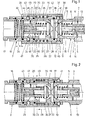
- Fig. 1 einen Schnitt durch die beiden ersten Ausführungsformen der Schnellverschlusskupplung beim Einstecken des Steckerventils in das Muffenventil,
- Fig. 2 einen Schnitt durch die beiden ersten Ausführungsformen während des Kuppelns nach Freigabe der beiden Sperrkugelverriegelungen,
- Fig. 3 einen Schnitt durch die beiden ersten Ausführungen der Schnellverschlusskupplung in einem weiteren Stadium der Kupplungsbewegung,
- Fig. 4 einen Schnitt durch die beiden ersten Ausführungen der Schnellverschlusskupplung in gekuppelter und verriegelter Stellung der beiden Sperrkugelverriegelungen,
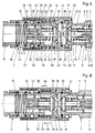
- Fig. 5 einen Schnitt durch zwei weitere Ausführungsformen der Schnellverschlusskupplung beim Einstecken des Steckerventils in das Muffenventil,
- Fig. 6 einen Schnitt durch die weiteren Ausführungsformen während des Kuppelns nach Freigabe der beiden Sperrkugelverriegelungen,
- Fig. 7 einen Schnitt durch die weiteren Ausführungen der Schnellverschlusskupplung in einem weiteren Stadium der Kupplungsbewegung, und
- Fig. 8 einen Schnitt durch die weiteren Ausführungen der Schnellverschlusskupplung in gekuppelter und verriegelter Stellung der beiden Sperrkugelverriegelungen.
- 1 shows a section through the first two embodiments of the quick-release coupling when the plug valve is inserted into the socket valve,
- 2 shows a section through the two first embodiments during coupling after the two locking ball locks have been released,
- 3 shows a section through the first two versions of the quick-release coupling in a further stage of the coupling movement,
- 4 shows a section through the first two versions of the quick-release coupling in the coupled and locked position of the two locking ball locks,
- 5 shows a section through two further embodiments of the quick-release coupling when the plug valve is inserted into the socket valve,
- 6 shows a section through the further embodiments during coupling after release of the two locking ball locks,
- 7 shows a section through the further designs of the quick-release coupling in a further stage of the coupling movement, and
- Fig. 8 shows a section through the other versions of the quick release coupling in the coupled and locked position of the two locking ball locks.
Jede Schnellverschlusskupplung besteht grundsätzlich aus einem Steckerventil 1 und einem Muffenventil 2. Von dem Steckerventil 1 ist nur eine einzige Ausführungsform gezeigt, während das Muffenventil in der oberen Zeichnungshälfte eine erste Ausführungsform und in der unteren Zeichnungshälfte eine zweite Ausführungsform in sämtlichen Figuren zeigt.Each quick release coupling basically consists of a
Das Steckerventil 1 besteht im wesentlichen aus einem Kupplungskörper 3 mit einem Sitz 4. Im Kupplungskörper 3 ist der Sternkörper 5, der über den Umfang verteilt drei abstehende Arme 6 aufweist, mit Hilfe des Sicherungsringes 7 gelagert. Ansonsten ist der Sternkörper 5 hülsenförmig ausgebildet und besitzt mittig eine Durchbohrung 8, in der der Schaft 9 eines Ventilkörpers 10 verschiebbar geführt ist. Der Ventilkörper 10 bildet mit dem Sitz 4 des Kupplungskörpers 3 ein Rückschlagventil 10, 4, welches die betreffende Leitung, die mit dem Steckerventil 1 verbunden ist, wie ersichtlich, abschliesst. Der Ventilkörper 10 wird gegen den Sitz 4 mit Hilfe einer Schliessfeder 11 gedrückt, die anderseits den Sternkörper 5 an dem Sicherungsring 7 in Anlage hält. Der Ventilkörper 10 ragt in geschlossener Stellung über die Stirnwand 12 des Steckerventils 1 um das Mass a' hinaus. In der Durchbohrung 8 ist weiterhin mit Hilfe eines Gewindes die Einstellschraube 13 gelagert, deren vorderes Ende einen Anschlag 14 für das Ende des Schaftes 9 bzw. den Ventilkörper 10 bildet. Die Einstellschraube 13 wird im Sternkörper 5 mit Hilfe des Gewindes so eingestellt, dass sich der Anschlag 14 in der Entfernung a' vom Ende des Schaftes 9 des Ventilkörpers 10 befindet. Der Ventilkörper 10 kann also zwischen seiner Offenstellung und seiner Schliessstellung den Ventilhub a' zurücklegen.The
Der Kupplungskörper 3 besitzt an der dargestellten Stelle eine umlaufende Verriegelungsnut 15, die mit einer noch später zu beschreibenden Sperrkugelverriegelung zur Verriegelung des Steckerventils 1 mit dem Muffenventil 2 in der gekuppelten Stellung und zur Freigabe der beiden Teile 1, 2 in der entkuppelten Stellung zusammenwirkt.The
Das Muffenventil 2 besitzt nun ebenfalls ähnlich wie das Steckerventil 1 einen Kupplungskörper 16, der auf ein Anschlussstück 17 aufgeschraubt ist, wobei eine Dichtung 18 den Innenraum druckdicht abschliesst. Bei der jeweils oben gezeichneten Ausführungsform ist im Kupplungskörper 16 eine Sitzhülse 19 verschiebbar gelagert, in welcher ein Sternkörper 20 mit Hilfe des Sicherungsringes 21 gelagert ist. Die Sitzhülse 19 trägt den Sitz 22. Bei der jeweils in der unteren Hälfte jeder Zeichnung dargestellten Ausführungsform fehlt die gesonderte Einschaltung der Sitzhülse 19. Statt dessen ist der Sternkörper 20 direkt im Kupplungskörper 16 verschiebbar gelagert. Zu diesem Zweck weist der Sternkörper 20 in der zweiten Ausführungsform eine Gleithülse 23 auf. In beiden Fällen besitzt der Sternkörper 20 beispielsweise drei radial abstehende Arme 24, zwischen denen über den Umfang gesehen die Strömung stattfinden kann. Bei der Ausführungsform des Sternkörpers 20 mit Gleithülse 23 ist der Sitz 22 vom Kupplungskörper 16 gebildet.Similar to the
Ähnlich wie bei dem Steckerventil 1 ist auch an dem Muffenventil 2 mittig an dem Sternkörper 20 eine Bohrung 25 vorgesehen, die den Schaft 26 des Ventilkörpers 27 verschieblich aufnimmt. Der Ventilkörper 27 bildet mit dem Sitz 22 das Rückschlagventil 22, 27 des Muffenventils 2. Das vordere Ende des Ventilkörpers 27 ragt über die Stirnebene 28 um das Mass a vor. In dem Sternkörper 20 ist eine Einstellschraube 29 mit Hilfe eines Gewindes ver- und einstellbar angeordnet, deren vorderes Ende einen Anschlag 30 für das hintere Ende des Schaftes 26 bzw. des Ventilkörpers 27 bildet. Die Einstellschraube 29 wird so eingestellt, dass der Ventilkörper 27 beim Öffnen den Ventilhub a ausführen kann, bevor er mit seinem Schaft 26 auf den Anschlag 30 auftrifft. Zwischen dem Sternkörper 20 und dem Ventilkörper 27 ist die Schliessfeder 31 eingeschaltet. Der Ventilhub a des Muffenventils 2 entspricht in etwa dem Ventilhub a' des Steckerventils 1. Beide Ventilhübe a und a' unterscheiden sich nur durch herstellungsbedingte Toleranzen. Grundsätzlich wird bei der Fertigung das gleiche Mass angestrebt und eingestellt.Similar to the
Der Sternkörper 20 ist bei der oberen Ausführungsform über die Sitzhülse 19 bzw. mit dieser und bei der unteren Ausführungsform direkt über seine Gleithülse 23 im Kupplungskörper 16 axialverschieblich gelagert, wobei für Abdichtzwecke die beiden Dichtungen 32 und 33 angeordnet sind. In beiden Fällen wird damit erreicht, dass der Sternkörper 20 gegenüber dem Kupplungskörper 16 um das Mass b axial verschiebbar ist. Das Mass b ist mindestens gleichgross wie der Ventilhub a' (bzw. a) ausgebildet, zwecks erleichterter Fertigung jedoch grösser gewählt. Auf jeden Fall wird damit ermöglicht, dass der Ventilkörper 27 des Muffenventils 2 insgesamt um den doppelten Ventilhub 2a verschiebbar gelagert ist, während der Ventilkörper 10 des Steckerventils 1 nur um den einfachen Ventilhub a' verschiebbar ist. Der Sternkörper 20 mit seiner Gleithülse 23 bzw. die gesonderte Sitzhülse 19 stützen sich über eine Druckfeder 34 an dem Anschlussstück 17 oder an einem Absatz des Kupplungskörpers 16 ab. Die Kraft der Druckfeder 34 ist grösser gewählt als die Kraft der Schliessfeder 31, so dass auf diese Weise eine eindeutige zeitliche Folge der Relativbewegungen festgelegt ist.The
Der Kupplungskörper 16 wird von einer Schiebehülse 35 umgeben, die hier als gemeinsame Schiebehülse ausgebildet ist und zur Betätigung von zwei verschiedenen Sperrkugelverriegelungen, wie nachfolgend noch erläutert wird, dient. Die Schiebehülse 35 ist an dem Kupplungskörper 16 mit Hilfe der Feder 36 in beiden Richtungen verschiebbar gelagert. Die gesamte Schnellverschlusskupplung ist als sog. Zug-Druck-Kupplung ausgebildet, d. h. die Schiebehülse 35 kann in beiden Richtungen gegenüber dem Kupplungskörper zum Zwecke der Freigabe der beiden Sperrkugelverriegelungen verschoben werden.The
Im einzelnen besitzt die Schiebehülse 35 einen relativ breit ausgebildeten Verriegelungsnocken 37, an welchen zwei Ausweichnuten 38 und 39 nach beiden Richtungen anschliessen. An der Stelle des Verriegelungsnockens 37 besitzt der Kupplungskörper 16 in an sich bekannter Weise eine Reihe von radialen Durchbrechungen 40, in welchen Kugeln 41 gelagert sind. Der Verriegelungsnocken 37 bildet in Verbindung mit den Ausweichnuten 38, 39 den Kugeln 41 und der Verriegelungsnut 15 des Steckerventils 1 eine erste Sperrkugelverriegelung 15, 37, 38, 39, 40, 41, welche zur Verriegelung von Steckerventil 1 und Muffenventil 2 in der gekuppelten Stellung bzw. zur Freigabe der beiden Teile in der entkuppelten Stellung dient. Derartige Sperrkugelverriegelungen sind an sich bekannt und bedürfen daher keiner weiteren Beschreibung.In detail, the sliding
Zur Abdichtung zwischen Steckerventil 1 und Muffenventil 2 ist am Kupplungskörper 16 des Muffenventils 2 die weitere Dichtung 42 untergebracht.For sealing between the
Die gemeinsame Schiebehülse 35 dient gleichzeitig zur Betätigung einer zweiten Sperrkugelverriegelung. Zu diesem Zweck besitzt die Schiebehülse 35 einen weiteren umlaufend ausgebildeten Verriegelungsnocken 43, der gegenüber dem Verriegelungsnocken 37 vergleichsweise weniger breit ausgebildet ist.The common sliding
Bei den Ausführungsformen der Fig. 5 bis 8 ist an der Schiebehülse 35 ein umlaufend ringförmig ausgebildeter Verriegelungsnocken 43 axialverschieblich gelagert, der gegenüber dem Verriegelungsnocken 37 vergleichsweise weniger breit ausgebildet sein kann. An dem Verriegelungsnokken 43 schliessen sich nach beiden Seiten wiederum Ausweichnuten 44 und 45 an. Diesen bzw. dem Verriegelungsnocken 43 zugeordnet besitzt der Kupplungskörper 16 (Fig. 1 bis 8) mehrere über den Umfang verteilt angeordnete Durchbrechungen 46 zur Aufnahme der Kugeln 47. Eine umlaufende Verriegelungsnut 48 ist in der Sitzhülse 19 bzw. in der Gleithülse 23 des Sternkörpers 20 aussen eingearbeitet. Der Verriegelungsnocken 43 bildet in Verbindung mit den Ausweichnuten 44, 45, den Durchbrechungen 46 in dem Kupplungskörper 16, den Kugeln 47 und der Verriegelungsnut 48 die zweite Sperrkugelverriegelung 43 bis 48, welches zur Verriegelung des Sternkörpers 20 gegenüber dem Kupplungskörper 16 bzw. in seiner anderen Stellung zur Freigabe dient. Die zweite Sperrkugelverriegelung 43 bis 48 bildet in Verbindung mit dem Anschlag 30 an der Einstellschraube 29 des Sternkörpers 20 einen ein- und ausrückbaren Anschlag zur Begrenzung bzw. Freigabe der axialen Bewegung des Ventilkörpers 27. Wenn die zweite Sperrkugelverriegelung 43 bis 48 verriegelt ist, wie dies Fig. 1 zeigt, ist der Anschlag 30 eingerückt, so dass der Ventilkörper 27 maximal den einfachen Ventilhub a zurücklegenkann, falls auf die Spitze des Ventilkörpers 27 eine entsprechende Kraft ausgeübt wird, die zur Überwindung der Kraft der Schliessfeder 31 führt. Ist dagegen die zweite Sperrkugelverriegelung 43 bis 48 ausgerückt bzw. freigegeben, wie dies beispielsweise Fig. 2 zeigt, dann kann der Ventilkörper 27 nicht nur den einfachen Ventilhub a ausführen, sondern relativ zu der Stirnebene 28 den doppelten Ventilhub zurücklegen, der sich aus der Summe der einzelnen Ventilhübe a + a'z2-a zusammensetzt.5 to 8, a circumferentially
Bei den Ausführungsformen der Fig. 5 bis 8 bilden die Ausweichnuten 44 und 45 eine axial durchgehende Ausnehmung, in der der ringförmige Verriegelungsnocken 43 begrenzt axialverschieblich gegenüber der gemeinsamen Schiebehülse 35 gelagert und durch zwei Federn 54 und 55 in Richtung auf die axiale Mittellage seines Hubes beaufschlagt ist.In the embodiments of FIGS. 5 to 8, the
Es versteht sich, dass anstelle der gemeinsamen Schiebehülse 35 auch je eine Schiebehülse zur Betätigung der ersten Sperrkugelverriegelung 15, 37 bis 41 und eine weitere Schiebehülse zur Betätigung der zweiten Sperrkugelverriegelung 43 bis 48 vorgesehen sein könnte. Auch dabei könnte der Verriegelungsnocken 43 gemäss den Fig. 5 bis 8 axialverschieblich in der einen Schiebehülse gelagert sein. Die gemeinsame Schiebehülse 35 zur Betätigung beider Sperrkugelverriegelungen vereinfacht jedoch die Handhabung wesentlich (Fig. 1 bis 8).It goes without saying that instead of the common sliding
Hinsichtlich der Wirkungsweise sei zunächst die in den vier Figuren jeweils in der unteren Hälfte dargestellte Ausführungsform betrachtet:
- Die Schnellverschlusskupplung ist auch unter Druck kuppelbar, d.h. dass eine Leitung der beiden zu verbindenden Leitungsteile unter Druck stehen kann. Bei dem in der Zeichnung dargestellten Ausführungsbeispiel möge die Leitung, die an
das Steckerventil 1 angeschlossen ist, unter Druck stehen, so dassdas Rückschlagventil Druck der Schliessfeder 11, sondern auch durch den Druck des eingesperrten Mediums beaufschlagt und in der Schliesslage gehalten wird.Die am Muffenventil 2 angeschlossene Leitung ist drucklos. BeimEinführen des Steckerventils 1 indas Muffenventil 2 können die Teile zunächst so weit ineinander gesteckt werden, wie dies Fig. 1 zeigt. Die Phase ander Stirnwand 12 stösst damit andie Kugeln 41 der ersten Sperrkugelverriegelung 15, 37bis 41 an, welches sich in der verriegelten Stellung befindet. Anschliessend wird dieSchiebehülse 35gemäss den Pfeilen 49 in Fig. 2 (oder in der entgegengesetzten Richtung) relativ gegenüberdem Kupplungskörper 16 verschoben, so dass sowohl die ersteSperrkugelverriegelung bis 41, als auch diezweite Sperrkugelverriegelung 43bis 48 freigegeben bzw. entriegelt wird. Bei den Ausführungsbeispielen der Fig. 5bis 8 halten bzw. schieben die Federn 54 und 55den Verriegelungsnocken 43 in seine Mittellage. In allen Ausführungsformen können dieKugeln 41 indie Ausweichnut 39 ausweichen, so dassdas Steckerventil 1 weiter indas Muffenventil 2 hineingeschoben werden kann.Da das Rückschlagventil Einschiebebewegung das Rückschlagventil auf dem Anschlag 30 zur Anlage kommt. Diese Zwischenstellung ist in Fig. 2 dargestellt. Da dieSchliessfeder 31 schwächer ausgebildet ist als dieDruckfeder 34, wird, wie in Fig. 2 dargestellt, sich zunächst der Ventilkörper 27 gegenüberdem Sternkörper 20 verschieben. Wäredagegen die Schliessfeder 31 stärker ausgebildet als dieDruckfeder 34, so würde sich zunächst der Sternkörper 20 relativ zudem Kupplungskörper 16 verschieben. Da mit dem Verschieben der Schiebehülse 35 auch diezweite Sperrkugelverriegelung 43bis 48 in die Freigabeposition gekommen ist,kann das Steckerventil 1 bei geschlossenem Rückschlagventil 10, 4 jedoch noch weiter indas Muffenventil 2 eingeschoben werden, wobei jetzt überden Anschlag 30der Sternkörper 20 mitgenommen wird, so dass sich das Mass b verkleinert.Der Ventilkörper 27 legt jetzt zusätzlich zu dem einfachen Ventilhub a einen weiteren Ventilhub a zurück, so dass der Ventilkörper 27 insgesamt etwa den doppelten Ventilhub 2a ausführt. Diese Stellung der Teile ist in Fig. 3 wiedergegeben. Es versteht sich, dass dabei dieKugeln 47 aus der Verriegelungsnut 48 herausgetreten und indie Ausweichnut 45 verschoben worden sind. Nach dem Loslassen der Schiebehülse 35 hat sich diese inRichtung der Pfeile 50 in Fig. 3 bewegt, so dass die ersteSperrkugelverriegelung bis 41 schon in seine Schliessposition zurückgekehrt ist, während diezweite Sperrkugelverriegelung 43bis 48 noch offen ist. Dabei wird für die Ausführungsformen der Fig. 5bis 8 die Feder 54 zusammengedrückt und die Feder 55 teilentlastet. Dies bedeutet, wie in Fig. 3bis 7 dargestellt, dassdas Steckerventil 1 bereitsmit dem Muffenventil 2 gekuppelt ist, so dassdas Steckerventil 1 nicht mehraus dem Muffenventil 2 herausgezogen oder herausgedrückt werden kann. Eine auf dem Aussenumfang des Kupplungskörpers 16angebrachte Markierung 51, beispielsweise in Form einer umlaufenden Einkerbung, deckt sich in dieser Stellung mit der Stirnwand der Schiebehülse 35 (Fig. 3), so dass von aussen an der Schnellverschlusskupplung erkennbar ist, dass die ersteSperrkugelverriegelung bis 41 sich bereits in der verriegelten Stellung befindet und hinsichtlich der Fig. 1bis 4die zweite Sperrkugelverriegelung 43bis 48 noch nicht verriegelt ist.
- The quick release coupling can also be coupled under pressure, ie a line of the two line parts to be connected can be under pressure. In the embodiment shown in the drawing, the line connected to the
plug valve 1 may be under pressure so that thecheck valve closing spring 11 but also by the pressure of the locked-in medium the closed position is maintained. The line connected tosocket valve 2 is depressurized. When theplug valve 1 is inserted into thesocket valve 2, the parts can initially be inserted into one another as far as is shown in FIG. 1. The phase on theend wall 12 thus abuts theballs 41 of the firstlocking ball lock sleeve 35 is then displaced relative to thecoupling body 16 according to thearrows 49 in FIG. 2 (or in the opposite direction), so that both the firstlocking ball lock locking ball lock 43 to 48 are released or is unlocked. 5 to 8, the springs 54 and 55 hold or push thelocking cam 43 into its central position. In all embodiments, theballs 41 can move into theescape groove 39, so that theplug valve 1 can be pushed further into thesleeve valve 2. Since thecheck valve check valve valve body 27 covers the simple valve stroke a and thus with itsstem 26 on thestop 30 Facility is coming. This intermediate position is shown in Fig. 2. Since theclosing spring 31 is weaker than thecompression spring 34, thevalve body 27 will first shift relative to thestar body 20, as shown in FIG. 2. If, on the other hand, the closingspring 31 were made stronger than thecompression spring 34, thestar body 20 would first shift relative to thecoupling body 16. Since the secondlocking ball lock 43 to 48 has also come into the release position with the displacement of the slidingsleeve 35, theplug valve 1 can still be pushed further into thesleeve valve 2 when thecheck valve star body 20 now being carried along via thestop 30 so that the dimension b decreases. In addition to the simple valve lift a, thevalve body 27 now covers another valve lift a, so that thevalve body 27 performs approximately twice the valve lift 2a overall. This position of the parts is shown in Fig. 3. It goes without saying that theballs 47 have emerged from the lockinggroove 48 and have been moved into theescape groove 45. After releasing the slidingsleeve 35, it has moved in the direction of thearrows 50 in FIG. 3, so that the firstlocking ball lock locking ball lock 43 to 48 is still open. For the embodiments of FIGS. 5 to 8, the spring 54 is compressed and the spring 55 is partially relieved. As shown in FIGS. 3 to 7, this means that theplug valve 1 is already coupled to thesocket valve 2, so that theplug valve 1 can no longer be pulled out or pushed out of thesocket valve 2. Amark 51 on the outer circumference of thecoupling body 16, for example in the form of a circumferential notch, coincides in this position with the end wall of the sliding sleeve 35 (FIG. 3), so that from the outside on the quick-release fastener final clutch can be seen that the firstlocking ball lock locking ball lock 43 to 48 has not yet been locked.
Wird jetzt auf die Leitung, die mit dem Muffenventil 2 verbunden ist, Druck gegeben, beispielsweise durch Einschalten der Druckmittelquelle, so strömt das Druckmedium über die Zwischenräume zwischen den Armen 24 über das geöffnete Rückschlagventil 22, 27 gegen den Ventilkörper 10 und belastet diesen damit zusätzlich entgegen der Kraft der Schliessfeder 11 und des dort eingesperrten Druckes. Zusätzlich wirkt auf den Ventilkörper 10 über den Ventilkörper 27 der Druck der Druckfeder 34, so dass insgesamt oder bei entsprechender Druckhöhe auf jeden Fall eine Öffnungsbewegung des Rückschlagventils 10, 4 erfolgt, so dass der Druckausgleich hergestellt ist. Infolge der Strömung des Druckmediums aus der an dem Muffenventil 2 angeschlossenen Leitung in Richtung auf die Leitung des Steckerventils 1 wirkt dieser Druck auch auf die Rückseite des Ventilkörpers 27, wobei diese Bewegung durch die Kraft der Druckfeder 34 unterstützt wird. Auf diese Weise bewegt sich der Ventilkörper 27 wiederum um den einfachen Ventilhub a' nach rechts, wobei der Ventilkörper 10 mitgenommen wird und selbstverständlich ebenfalls den einfachen Ventilhub a' ausführt, bis sein Schaft 9 auf dem festen Anschlag 14zur Anlage kommt. Diese Stellung der Teile ist in Fig. 4 dargestellt. Während dieser Bewegung, die der Ventilkörper 27 gemeinsam mit dem Sternkörper 20 ausführt, ohne dass der Schaft 26 von dem Anschlag 30 freikommt, verschiebt sich auch die Gleithülse 23 des Sternkörpers 20 so weit nach rechts, dass die Verriegelungsnut 48 in den Bereich der Kugeln 47 gelangt, so dass sich zusätzlich zu der ersten Sperrkugelverriegelung auch das zweite Kugelgesperre 43 bis 48 nunmehr schliessen kann. Diese Schliessstellung wird in den Ausführungsformen der Fig. 5 bis 8 durch die axialverschiebliche Lagerung des Verriegelungsnockens 43 und die Kraft der Feder 54 ermöglicht. Sowohl die erste Sperrkugelverriegelung 15, 37 bis 41 als auch die zweite Sperrkugelverriegelung 43 bis 48 befinden sich dann in der verriegelten Stellung, wie dies Fig. 4 bzw. 8 zeigt. Eine weitere Markierung 52 (Fig. 4) auf dem Aussenumfang des Kupplungskörpers 16 wird damit relativ zu dem Ende der Schiebehülse 35 sichtbar, wenn sich diese gemäss Pfeil 53 in die in Fig. gezeichnete Endlage verschoben hat. Der Aussenumfang der Schiebehülse 35 in Verbindung mit einer Ausnehmung 56 zeigt an, dass sich der Verriegelungsnocken 43 gemäss Pfeil 53 in die in Fig. 8 gezeichnete Endlage verschoben hat. Die Markierungen 51 und 52 zeigen verlässlich an, dass beide Sperrkugelverriegelungen verriegelt sind. Dies bedeutet, dass auch der Anschlag 30 wieder eingerückt, also wirksam ist. Die beiden Ventilkörper 10 und 27 befinden sich somit in fest verriegelter Lage zwischen den Anschlägen 14 und 30, so dass auch Druckschwankungen des Druckmediums zu keiner wesentlichen Verschiebung der Ventilkörper 10, 27 in den Teilen 1, 2 der Schnellverschlusskupplung führen können. Bei dieser Betrachtung ist vorausgesetzt, dass die Stirnfläche 12 des Steckerventils 1 und die Stirnebene 28 des Muffenventils 2 in der gekuppelten Stellung eine gemeinsame Stirnflächenebene einnehmen, wie dies Fig. 4 zeigt.If pressure is now applied to the line which is connected to the
Zum Zwecke der Entkupplung wird die Schiebehülse 35 aus der Stellung gemäss Fig. 4 bis 8 heraus entweder in Richtung der Pfeile 49 oder in der entgegengesetzten Richtung betätigt, so dass die beiden Sperrkugelverriegelungen 15, 37 bis 41 und 43 bis 48 entriegelt werden. Je nach den herrschenden Druckverhältnissen wird das Steckerventil 1 aus dem Muffenventil 2 herausgedrückt, wobei sich beide Rückschlagventile 20, 4 und 22, 27 in die Schliessstellung bewegen, wie dies in Fig. 1 bzw. 5 dargestellt ist.For the purpose of uncoupling, the sliding
Die in den Fig. 1 bis 4 bzw. 5 bis 8 in der oberen Hälfte dargestellte Ausführungsform besitzt eine analoge Wirkungsweise, wobei hier der Sternkörper 20 gemeinsam mit der Sitzhülse 19 verschoben wird. Die Zeichnungen zeigen die verschiedenen Zwischenstellungen unter der Voraussetzung, dass die Druckfeder 34 stärker ausgebildet ist als die Schliessfeder 31. Macht man hingegen die Schliessfeder 31 stärker als die Druckfeder 34, so hätte dies eine etwas andere Wirkungsweise zur Folge. Bei der Zwischenstellung nach Fig. 2 bzw. 6 entstünde dann der möglicherweise erwünschte Vorteil, dass beide Rückschlagventile 4, 10 und 22, 27 in dieser Zwischenstellung geschlossen wären. Sofern man dann noch das Mass b mindestens doppelt so gross wählt wie den einfachen Ventilhub a', könnte eine solche Kupplung hinsichtlich ihrer ersten Sperrkugelverriegelung vollkommen geschlossen werden, wobei sich in dieser Schliessstellung selbst beide Rückschlagventile 10, 4 und 22, 27 noch in der Schliessstellung befinden. Es müsste dann allerdings durch entsprechenden Druckaufbau bzw. Druckabsenkung oder auf andere Weise erreicht werden, dass beide Rückschlagventile eine Offenstellung gemäss Fig. 4 bzw. 8 erreichen können und eine entsprechende Verriegelung dieser Stellung erfolgt.The embodiment shown in FIGS. 1 to 4 or 5 to 8 in the upper half has an analogous mode of operation, in which case the
Es versteht sich, dass bei den dargestellten Ausführungsformen die Schnellverschlusskupplung selbstverständlich auch dann gekuppelt und entkuppelt werden kann, wenn keine der beiden jeweils an das Steckerventil 2 und an das Muffenventil 2 angeschlossenen Leitungen während des Kupplungs- bzw. Entkupplungsvorganges unter Druck stehen. In einem solchen Fall tritt dann je nach der Abstimmung der Federn 11, 31, 34 untereinander eine unterschiedliche Reihenfolge der Bewegungen der einzelnen Ventilkörper relativ zu den Kupplungskörpern 3 bzw. 16 auf. Ist z.B. die Druckfeder 34 stärker ausgebildet als die Schliessfeder 31 und die Schliessfeder 11, wobei die Schliessfeder 11 und die Schliessfeder 31 kraftmässig etwa gleich sind, dann wird beim Kupplungsvorgang ohne Druck der Ventilkörper 10 den einfachen Ventilhub a' ausführen, während der Ventilkörper 27 den einfachen Ventilhub a ausführt, so dass unmittelbar die Offenstellung der beiden Rückschlagventile 4, 10 und 22, 27 gemäss Fig. 4 erreicht wird. Aber auch in diesem Falle wird unmittelbar die Verriegelungsstellung erreicht, wenn der Kupplungsvorgang beendet ist und die Schiebehülse ihre Endposition erreicht hat. Der Durchgang durch die Schnellverschlusskupplung ist geöffnet und bleibt geöffnet, weil die Ventilkörper schon vor dem Einschalten der Druckquelle verriegelt sind. Ein einmaliger Schliessvorgang im Sinne einer doppelten Hubbewegung ist zur Erreichung der Verriegelungsstellung nicht mehr erforderlich.It goes without saying that in the illustrated embodiments the quick-release coupling can of course also be coupled and uncoupled if neither of the two lines respectively connected to the
Claims (10)
Priority Applications (1)
| Application Number | Priority Date | Filing Date | Title |
|---|---|---|---|
| AT81100845T ATE11332T1 (en) | 1980-02-14 | 1981-02-06 | QUICK-RELEASE COUPLING ALSO CONNECTABLE UNDER PRESSURE. |
Applications Claiming Priority (4)
| Application Number | Priority Date | Filing Date | Title |
|---|---|---|---|
| DE19803005490 DE3005490C2 (en) | 1980-02-14 | 1980-02-14 | Quick-release coupling that can also be coupled under pressure |
| DE3005490 | 1980-02-14 | ||
| DE3039072 | 1980-10-16 | ||
| DE19803039072 DE3039072C2 (en) | 1980-10-16 | 1980-10-16 | Quick-release coupling that can also be coupled under pressure |
Publications (3)
| Publication Number | Publication Date |
|---|---|
| EP0034312A2 EP0034312A2 (en) | 1981-08-26 |
| EP0034312A3 EP0034312A3 (en) | 1982-05-12 |
| EP0034312B1 true EP0034312B1 (en) | 1985-01-16 |
Family
ID=25783712
Family Applications (1)
| Application Number | Title | Priority Date | Filing Date |
|---|---|---|---|
| EP19810100845 Expired EP0034312B1 (en) | 1980-02-14 | 1981-02-06 | Quick-connection coupling also connectable under pressure |
Country Status (4)
| Country | Link |
|---|---|
| US (1) | US4388947A (en) |
| EP (1) | EP0034312B1 (en) |
| DK (1) | DK150388C (en) |
| ES (1) | ES500073A0 (en) |
Cited By (2)
| Publication number | Priority date | Publication date | Assignee | Title |
|---|---|---|---|---|
| DE3632967A1 (en) * | 1986-09-27 | 1988-04-07 | Wws Wohnwaerme Service Gebr Le | Sealing and coupling device |
| DE19953243A1 (en) * | 1999-11-04 | 2001-05-17 | Voswinkel Kg | Rapid connector which can be fastened under pressure, for connecting agricultural machinery to tractors has wedge-shaped compensating component which protects valve stem and generates compensating pressure against that holding valve shut |
Families Citing this family (28)
| Publication number | Priority date | Publication date | Assignee | Title |
|---|---|---|---|---|
| ES8702623A1 (en) * | 1985-04-24 | 1987-01-01 | Schmelzer Corp | Quick-connect fluid fitting assembly |
| US4583711A (en) * | 1985-06-28 | 1986-04-22 | Parker-Hannifin Corporation | Rigid mount coupler with flow check stop |
| US4842309A (en) * | 1987-05-20 | 1989-06-27 | Schmelzer Corporation | Quick-connect fluid fitting assembly |
| IT1215734B (en) * | 1988-01-19 | 1990-02-22 | Faster Srl | PERFECTED QUICK COUPLING, PLUGGABLE WITH MALE PRESSURE AND SUITABLE TO GUARANTEE FLOW IN TWO WAYS, WITHOUT DANGER OF INTERRUPTION. |
| IT1218077B (en) * | 1988-06-15 | 1990-04-12 | Dideco Spa | FLUID INTERCEPTION DEVICE IN A LINE |
| SE469989B (en) * | 1989-01-19 | 1993-10-18 | Nyberg Bo Erik | Valve device for quick connections for, for example, high pressure oil |
| US4971110A (en) * | 1989-12-19 | 1990-11-20 | Semi-Gas Systems, Inc. | Face seal shut-off valve |
| JPH0753031Y2 (en) * | 1991-03-26 | 1995-12-06 | 日東工器株式会社 | Pipe fitting for sampling pipe |
| US5255699A (en) * | 1992-12-07 | 1993-10-26 | Parker-Hannifin Corporation | Nipple with integral crossbar actuator and check valve |
| US6029701A (en) * | 1995-09-19 | 2000-02-29 | Parker Hannifin Sa | Quick-connect coupling for pressurized fluid lines |
| SE510095C2 (en) * | 1996-02-23 | 1999-04-19 | Dart Engineering Ag | Device for quick coupling |
| IT1289947B1 (en) * | 1997-02-21 | 1998-10-19 | Faster Srl | QUICK COUPLING |
| ITGE20010006U1 (en) * | 2001-03-30 | 2002-09-30 | Htm Sport Spa | TENSIONING DEVICE OF THE INSURANCE BELT OF GAS CYLINDERS INCLUDED ON THE BACK OF A JACKET OR SIMILAR FOR ACTIVITIES |
| GB0116989D0 (en) * | 2001-07-12 | 2001-09-05 | Chamberlain Luke | Boiler unit |
| FR2855239B1 (en) * | 2003-05-20 | 2005-08-12 | Parker Hannifin Sa | QUICK CONNECTOR FOR HYDRAULIC FLUID PIPES |
| FR2889728B1 (en) * | 2005-08-10 | 2007-10-05 | Staubli Faverges Sca | CONNECTOR ASSEMBLY FOR FLUIDIC CIRCUIT |
| GB2431702B (en) * | 2005-10-25 | 2008-06-04 | Diamould Ltd | Connection device for an underwater service line and associated mounting and ROV handle assemblies |
| FR2895058B1 (en) * | 2005-12-20 | 2008-03-14 | Parker Hannifin France Sas Soc | RIGID COUPLER FOR PRESSURIZED FLUID PIPES, FOR CONNECTING THESE PIPES WHILE PRESSURIZED FLUID SUBSISTS IN ONE OF THESE PIPES |
| TW200949121A (en) * | 2008-02-28 | 2009-12-01 | Nitto Kohki Co | Socket for pipe coupling and pipe coupling |
| WO2009107790A1 (en) * | 2008-02-28 | 2009-09-03 | 日東工器株式会社 | Socket for pipe joint and pipe joint |
| CN104684385A (en) * | 2012-01-07 | 2015-06-03 | Ivm知识产权有限公司 | A liquid applicator device |
| BR102013016280A2 (en) * | 2013-06-25 | 2015-08-18 | Dynamics Do Brasil Metalurgia Ltda | Hydraulic coupling enhancement for quick coupling |
| US9887478B2 (en) * | 2015-04-21 | 2018-02-06 | Varian Semiconductor Equipment Associates, Inc. | Thermally insulating electrical contact probe |
| EP3365527B1 (en) * | 2015-10-22 | 2019-12-04 | Parker-Hannifin Corporation | Quick coupling with volume displacement passage |
| FR3046209B1 (en) * | 2015-12-23 | 2018-02-16 | Staubli Faverges | RAPID CONNECTION FEMALE ELEMENT AND RAPID CONNECTION COMPRISING SUCH A FEMALE ELEMENT |
| US9899193B1 (en) | 2016-11-02 | 2018-02-20 | Varian Semiconductor Equipment Associates, Inc. | RF ion source with dynamic volume control |
| FR3080165B1 (en) * | 2018-04-12 | 2020-05-01 | Staubli Faverges | FITTING ELEMENT AND FITTING COMPRISING SUCH A FITTING ELEMENT |
| JP7150310B2 (en) * | 2018-07-27 | 2022-10-11 | サーパス工業株式会社 | FLUID TRANSFER CONNECTOR AND CONTROL METHOD THEREOF |
Family Cites Families (11)
| Publication number | Priority date | Publication date | Assignee | Title |
|---|---|---|---|---|
| GB1132383A (en) * | 1966-03-29 | 1968-10-30 | Exactor Sterling Ltd | Fluid line self sealing coupling |
| US3482602A (en) * | 1967-08-08 | 1969-12-09 | Noble Mfg Co | Hydraulic coupler |
| US3674051A (en) * | 1971-05-14 | 1972-07-04 | Safe Way Hydraulics | Hydraulic coupler |
| US3791411A (en) * | 1972-08-18 | 1974-02-12 | B Bogeskov | Hydraulic coupler |
| DE2642724C2 (en) * | 1976-09-23 | 1983-11-24 | Fischer, Wolf E., 7505 Ettlingen | Coupling for connecting hydraulic lines |
| US4098292A (en) * | 1977-01-24 | 1978-07-04 | Aeroquip Corporation | Locking means for self-sealing quick disconnect couplings |
| DE2712117C2 (en) * | 1977-03-19 | 1985-01-24 | Argus Gesellschaft Mbh, 7505 Ettlingen | Quick release coupling for hydraulic lines |
| DE2715417A1 (en) * | 1977-04-06 | 1978-10-12 | Argus Gmbh | Hydraulic pipe quick-action coupling - has locking mechanism restricting valve movement when flow takes place |
| CH626696A5 (en) * | 1977-03-19 | 1981-11-30 | Argus Gmbh | |
| DE2724630C3 (en) * | 1977-06-01 | 1980-01-24 | Robert Volker Ing.(Grad.) 7502 Malsch Pfeiffer | Pipeline coupling, in particular for high and extremely high pressure lines |
| DE2741027A1 (en) * | 1977-09-12 | 1979-03-22 | Fischer Wolf E Dipl Ing | CONNECTING COUPLING UNDER PRESSURE |
-
1981
- 1981-02-06 EP EP19810100845 patent/EP0034312B1/en not_active Expired
- 1981-02-11 US US06/233,659 patent/US4388947A/en not_active Expired - Lifetime
- 1981-02-13 DK DK62981A patent/DK150388C/en active
- 1981-02-13 ES ES500073A patent/ES500073A0/en active Granted
Cited By (3)
| Publication number | Priority date | Publication date | Assignee | Title |
|---|---|---|---|---|
| DE3632967A1 (en) * | 1986-09-27 | 1988-04-07 | Wws Wohnwaerme Service Gebr Le | Sealing and coupling device |
| DE19953243A1 (en) * | 1999-11-04 | 2001-05-17 | Voswinkel Kg | Rapid connector which can be fastened under pressure, for connecting agricultural machinery to tractors has wedge-shaped compensating component which protects valve stem and generates compensating pressure against that holding valve shut |
| DE19953243C2 (en) * | 1999-11-04 | 2003-10-23 | Voswinkel Kg | Quick-release coupling that can be coupled under pressure |
Also Published As
| Publication number | Publication date |
|---|---|
| ES8201714A1 (en) | 1981-12-16 |
| US4388947A (en) | 1983-06-21 |
| EP0034312A3 (en) | 1982-05-12 |
| DK62981A (en) | 1981-08-15 |
| DK150388C (en) | 1987-10-19 |
| ES500073A0 (en) | 1981-12-16 |
| DK150388B (en) | 1987-02-16 |
| EP0034312A2 (en) | 1981-08-26 |
Similar Documents
| Publication | Publication Date | Title |
|---|---|---|
| EP0034312B1 (en) | Quick-connection coupling also connectable under pressure | |
| EP0381069B1 (en) | Coupling sleeve for hydraulic connection lines | |
| EP0038056B1 (en) | Quick-acting coupling for hoses or the like | |
| EP0536434B1 (en) | Self-vented quick coupling for pressurized gas pipes, especially for compressed air pipes | |
| EP2427683B1 (en) | Coupling piece | |
| EP0013393A1 (en) | Joint for conduits | |
| EP0191384B1 (en) | Valve assembling | |
| DE1957879C3 (en) | Breakaway coupling for fluid lines | |
| DE19619839C1 (en) | Coupling for connecting hydraulic conduits | |
| EP0278420B1 (en) | Coupling of the quick acting type, especially for hydraulic conduits | |
| EP0184799A2 (en) | Vent coupling | |
| DE4025385C2 (en) | ||
| EP0096649B1 (en) | Quick action pressure as well as non-pressure coupling, especially for hydraulic conduits | |
| DE3005490C2 (en) | Quick-release coupling that can also be coupled under pressure | |
| EP0051201A1 (en) | Coupling for hydraulic systems | |
| DE3015601A1 (en) | Quick release coupling for hydraulic hose - is functional with coupling elements under pressure | |
| DE3410967C2 (en) | ||
| EP0187238B1 (en) | Connectible break-away pipe coupling, especially for hydraulic tubes, for plugs, also whilst being under pressure | |
| DE3039072C2 (en) | Quick-release coupling that can also be coupled under pressure | |
| EP1793154A2 (en) | Female part of a pneumatic coupling with vent | |
| DE1675373C3 (en) | Coupling for lines of flowing media | |
| DE4318840C2 (en) | Coupling for connecting hydraulic lines | |
| DE3728577C2 (en) | ||
| DE3637176A1 (en) | Leak-free hydraulic coupling | |
| DE1068962B (en) |
Legal Events
| Date | Code | Title | Description |
|---|---|---|---|
| PUAI | Public reference made under article 153(3) epc to a published international application that has entered the european phase |
Free format text: ORIGINAL CODE: 0009012 |
|
| AK | Designated contracting states |
Designated state(s): AT BE CH FR GB IT LU NL SE |
|
| 17P | Request for examination filed |
Effective date: 19811012 |
|
| PUAL | Search report despatched |
Free format text: ORIGINAL CODE: 0009013 |
|
| AK | Designated contracting states |
Designated state(s): AT BE CH FR GB IT LU NL SE |
|
| ITF | It: translation for a ep patent filed |
Owner name: DE DOMINICIS & MAYER S.R.L. |
|
| GRAA | (expected) grant |
Free format text: ORIGINAL CODE: 0009210 |
|
| AK | Designated contracting states |
Designated state(s): AT BE CH FR GB IT LU NL SE |
|
| REF | Corresponds to: |
Ref document number: 11332 Country of ref document: AT Date of ref document: 19850215 Kind code of ref document: T |
|
| ET | Fr: translation filed | ||
| PLBE | No opposition filed within time limit |
Free format text: ORIGINAL CODE: 0009261 |
|
| STAA | Information on the status of an ep patent application or granted ep patent |
Free format text: STATUS: NO OPPOSITION FILED WITHIN TIME LIMIT |
|
| 26N | No opposition filed | ||
| ITTA | It: last paid annual fee | ||
| EPTA | Lu: last paid annual fee | ||
| EAL | Se: european patent in force in sweden |
Ref document number: 81100845.7 |
|
| PGFP | Annual fee paid to national office [announced via postgrant information from national office to epo] |
Ref country code: FR Payment date: 20000118 Year of fee payment: 20 |
|
| PGFP | Annual fee paid to national office [announced via postgrant information from national office to epo] |
Ref country code: GB Payment date: 20000202 Year of fee payment: 20 |
|
| PGFP | Annual fee paid to national office [announced via postgrant information from national office to epo] |
Ref country code: BE Payment date: 20000218 Year of fee payment: 20 Ref country code: AT Payment date: 20000218 Year of fee payment: 20 Ref country code: CH Payment date: 20000218 Year of fee payment: 20 Ref country code: LU Payment date: 20000218 Year of fee payment: 20 Ref country code: SE Payment date: 20000218 Year of fee payment: 20 |
|
| PGFP | Annual fee paid to national office [announced via postgrant information from national office to epo] |
Ref country code: NL Payment date: 20000223 Year of fee payment: 20 |
|
| BE20 | Be: patent expired |
Free format text: 20010206 *AERPQUIP G.M.B.H. |
|
| PG25 | Lapsed in a contracting state [announced via postgrant information from national office to epo] |
Ref country code: LI Free format text: LAPSE BECAUSE OF EXPIRATION OF PROTECTION Effective date: 20010205 Ref country code: CH Free format text: LAPSE BECAUSE OF EXPIRATION OF PROTECTION Effective date: 20010205 Ref country code: GB Free format text: LAPSE BECAUSE OF EXPIRATION OF PROTECTION Effective date: 20010205 |
|
| PG25 | Lapsed in a contracting state [announced via postgrant information from national office to epo] |
Ref country code: NL Free format text: LAPSE BECAUSE OF EXPIRATION OF PROTECTION Effective date: 20010206 Ref country code: LU Free format text: LAPSE BECAUSE OF EXPIRATION OF PROTECTION Effective date: 20010206 Ref country code: AT Free format text: LAPSE BECAUSE OF EXPIRATION OF PROTECTION Effective date: 20010206 |
|
| PG25 | Lapsed in a contracting state [announced via postgrant information from national office to epo] |
Ref country code: SE Free format text: THE PATENT HAS BEEN ANNULLED BY A DECISION OF A NATIONAL AUTHORITY Effective date: 20010207 |
|
| REG | Reference to a national code |
Ref country code: CH Ref legal event code: PL Ref country code: GB Ref legal event code: PE20 Effective date: 20010205 |
|
| NLV7 | Nl: ceased due to reaching the maximum lifetime of a patent |
Effective date: 20010206 |
|
| EUG | Se: european patent has lapsed |
Ref document number: 81100845.7 |