EP0034079B1 - Procédé et dispositif pour stabiliser l'écoulement d'un mélange diphasique - Google Patents
Procédé et dispositif pour stabiliser l'écoulement d'un mélange diphasique Download PDFInfo
- Publication number
- EP0034079B1 EP0034079B1 EP81400105A EP81400105A EP0034079B1 EP 0034079 B1 EP0034079 B1 EP 0034079B1 EP 81400105 A EP81400105 A EP 81400105A EP 81400105 A EP81400105 A EP 81400105A EP 0034079 B1 EP0034079 B1 EP 0034079B1
- Authority
- EP
- European Patent Office
- Prior art keywords
- flow
- phase
- conduit
- gas
- location
- Prior art date
- Legal status (The legal status is an assumption and is not a legal conclusion. Google has not performed a legal analysis and makes no representation as to the accuracy of the status listed.)
- Expired
Links
Images
Classifications
-
- F—MECHANICAL ENGINEERING; LIGHTING; HEATING; WEAPONS; BLASTING
- F16—ENGINEERING ELEMENTS AND UNITS; GENERAL MEASURES FOR PRODUCING AND MAINTAINING EFFECTIVE FUNCTIONING OF MACHINES OR INSTALLATIONS; THERMAL INSULATION IN GENERAL
- F16L—PIPES; JOINTS OR FITTINGS FOR PIPES; SUPPORTS FOR PIPES, CABLES OR PROTECTIVE TUBING; MEANS FOR THERMAL INSULATION IN GENERAL
- F16L55/00—Devices or appurtenances for use in, or in connection with, pipes or pipe systems
-
- F—MECHANICAL ENGINEERING; LIGHTING; HEATING; WEAPONS; BLASTING
- F15—FLUID-PRESSURE ACTUATORS; HYDRAULICS OR PNEUMATICS IN GENERAL
- F15D—FLUID DYNAMICS, i.e. METHODS OR MEANS FOR INFLUENCING THE FLOW OF GASES OR LIQUIDS
- F15D1/00—Influencing flow of fluids
- F15D1/02—Influencing flow of fluids in pipes or conduits
-
- F—MECHANICAL ENGINEERING; LIGHTING; HEATING; WEAPONS; BLASTING
- F16—ENGINEERING ELEMENTS AND UNITS; GENERAL MEASURES FOR PRODUCING AND MAINTAINING EFFECTIVE FUNCTIONING OF MACHINES OR INSTALLATIONS; THERMAL INSULATION IN GENERAL
- F16L—PIPES; JOINTS OR FITTINGS FOR PIPES; SUPPORTS FOR PIPES, CABLES OR PROTECTIVE TUBING; MEANS FOR THERMAL INSULATION IN GENERAL
- F16L2101/00—Uses or applications of pigs or moles
- F16L2101/40—Separating transported fluids
Definitions
- the present invention relates to a method and a device for stabilizing the flow of a two-phase fluid and more particularly for making the mixture of gas and liquid making up this fluid more homogeneous.
- the problem to be solved is linked to two-phase flows, that is to say to the flow of a fluid of which a fraction is in the liquid state and the remaining fraction in the gaseous state.
- the pumping of two-phase fluids is ensured by conventional pumping equipment as long as the volumetric ratio of gas to liquid does not exceed a limit value close to 0.1 to 0, 2, or by specially designed equipment when the volumetric ratio is greater than this limit.
- the present invention provides a method for stabilizing the flow of a two-phase gas-liquid mixture in a pipe and thus reducing, in particular the formation of gas plugs in this flow, while at least one member is introduced into the pipe. adapted to split the two-phase flow into a plurality of separate flows and to recombine them by forming a substantially homogeneous flow downstream of said member, characterized in that this member is moved in the pipe to the location of the latter ci for which the best possible stabilization of the flow is observed, and in that it is immobilized at said location.
- the invention provides a device for stabilizing the flow of a two-phase gas-liquid mixture in a pipe and thus reducing, in particular the formation of gas plugs in this flow, this device comprising at least one member adapted to fractionate the two-phase flow in a plurality of separate flows which recombine forming a substantially homogeneous flow downstream of said organ, characterized in that said organ is removable inside the pipe and includes means allowing its immobilization at a location of the conduct chosen in advance.
- This method and this device making it possible to ensure good homogenization of the gas-liquid mixture thus preventing the formation of gas plugs and / or ensuring their disappearance when there is one in the flow of a two-phase fluid.
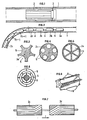
- Figure 1 schematically shows the principle of the invention which consists in positioning, in a conduit 1, traversed by a two-phase fluid, a member 2 adapted to make the mixture of gas and liquid more homogeneous.
- This member 2 is held in the duct 1 by immobilization means shown diagrammatically at 3.
- the member 2 is movable in the conduit 1, to be located in the most suitable place of the two-phase flow.
- the movement of the member 2 can be ensured by any known means such as an operating rod, a drive device circulating in a conduit under the action of a pressurized fluid.
- FIG. 2 schematically shows a member 2 composed of n elements 2a, 2b, ... 2n fixed end to end by articulated connection means 4 allowing relative rotation of the successive elements with respect to each other. In this way, the member 2 can be moved in the pipe 1 even if the latter has bent portions.
- connection means may consist of ball joints, cardan joints, or any other device known to the technician. For this reason, it is not necessary to illustrate in detail the embodiments of these connection means.
- each element making up the member 2 is chosen as a function of the smallest radius of curvature of the pipe 1.
- Each element 2a, 2b, ... 2n is adapted to split the two-phase flow into a plurality of separate flows and to combine them downstream, considering the direction of flow of the fluid.
- the conduits 5 of two consecutive elements can be paired: by considering the direction of flow of the fluids represented by the arrow f, the conduits 5 of the first element are first of all axial on a first portion then helical on a second portion, while the channels of the next element are first helical then axial.
- the helical parts will have a length close to half a pitch of the propeller.
- the elements 2a, 2b, ... 2n are made of a material compatible with the flow of fluid in which they are placed. The choice of material will therefore be made by the technician among metals, reinforced or unarmed plastics, etc.
- each element in the pipe is provided in a manner known per se by centralizers such as bosses 6 carried by each element (FIG. 8).
- centralizers such as bosses 6 carried by each element (FIG. 8).
- the dimensions and the spacing between the centering bosses are determined as a function of the internal diameter and the minimum radius of curvature of the pipe to ensure easy circulation of these elements in all the portions of the pipe.
- the introduction of the device into a conduit where a pressurized fluid circulates can be carried out by means of an introductory airlock, as shown diagrammatically in FIG. 9.
- This airlock is provided with obturation blocks 8 and 9, of purge lines 10 and 11 and a pressurization line 12.
- the device 2 is fixed to the end of an operating rod 13 which is used for its establishment and its maintenance in the desired portion of the pipe 1, which is for example here a pipeline for the transport of petroleum effluents.
- the place where the device according to the invention must be positioned can be determined by taking into account changes in pumping conditions and / or pressure fluctuations upstream and downstream of the device when the position of the device is varied. this. The device is then kept in the position where these conditions are optimal, that is to say for which the flow is most stable.
- the device according to the invention is introduced upstream of the pumping member. and it is moved in the pipeline until it reaches a position for which the maximum pumping rate is obtained substantially under stable conditions. The device is then kept in this position.
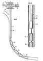
- the device 2 is maintained in a production well 14 by being fixed at the end of a motor-pump unit 16 suspended from a production casing 15.
- the immobilization means can also be composed of devices marketed for example by the company OTIS and generally comprising one or more retaining sleeves preferably integrated in rectilinear portions of the pipe 1 cooperating with a latching mandrel provided with suitable retractable fingers. to enter grooves in the retaining sleeve.
- This mandrel which is integral with the device 2, makes it possible to immobilize the latter at the desired location of the pipe.
- suitable recovery means make it possible to separate the attachment mandrel from the retaining sleeve.
- organs are well known to the technician and will therefore not be described in detail.
- Such devices are, for example, described in the 1976 OTIS catalog, page 19 for the retaining sleeves designated under the name of "Landing neeple” and page 43 for the mandrel designated under the name of "Pumpdown Lock Mandrel”.
- conduits we know enough at the present time the behavior of two-phase flows in conduits to determine with a good approximation the endoits of the conduit where the instabilities of the flow will appear, according to the hydro-dynamic parameters of the flow and the geometric characteristics. conduits. In this way, during the manufacture of the conduits, it is possible to provide for the implantation of several sleeves of different internal geometries, adapted to allow the attachment only of a particular type of mandrel whose geometry is complementary to that of a sleeve so that each mandrel can only be hung on the single sleeve of the corresponding type.
- the device can be used for pipes where condensate gases circulate. Indeed, it is known that condensate accumulations such as water appear at the lowest points of the pipes increasing the risk of corrosion in these places of the pipes.
- the device according to the invention maintained in these accumulation zones promotes the dispersion in the form of a mist of the accumulated liquids and reduces the risk of corrosion.
Landscapes
- Engineering & Computer Science (AREA)
- General Engineering & Computer Science (AREA)
- Mechanical Engineering (AREA)
- Physics & Mathematics (AREA)
- Fluid Mechanics (AREA)
- Physical Or Chemical Processes And Apparatus (AREA)
Applications Claiming Priority (2)
| Application Number | Priority Date | Filing Date | Title |
|---|---|---|---|
| FR8002054 | 1980-01-30 | ||
| FR8002054A FR2474614A1 (fr) | 1980-01-30 | 1980-01-30 | Methode et dispositif pour regulariser l'ecoulement d'un fluide diphasique |
Publications (2)
| Publication Number | Publication Date |
|---|---|
| EP0034079A1 EP0034079A1 (fr) | 1981-08-19 |
| EP0034079B1 true EP0034079B1 (fr) | 1983-07-06 |
Family
ID=9238041
Family Applications (1)
| Application Number | Title | Priority Date | Filing Date |
|---|---|---|---|
| EP81400105A Expired EP0034079B1 (fr) | 1980-01-30 | 1981-01-26 | Procédé et dispositif pour stabiliser l'écoulement d'un mélange diphasique |
Country Status (3)
| Country | Link |
|---|---|
| EP (1) | EP0034079B1 (enExample) |
| DE (1) | DE3160540D1 (enExample) |
| FR (1) | FR2474614A1 (enExample) |
Cited By (1)
| Publication number | Priority date | Publication date | Assignee | Title |
|---|---|---|---|---|
| US7303046B2 (en) | 2002-09-18 | 2007-12-04 | Savant Measurement Corporation | Apparatus for filtering ultrasonic noise within a fluid flow system |
Families Citing this family (8)
| Publication number | Priority date | Publication date | Assignee | Title |
|---|---|---|---|---|
| US4592201A (en) * | 1982-07-12 | 1986-06-03 | General Electric Company | Turbofan mixed flow exhaust system |
| FR2552173B1 (fr) * | 1983-09-19 | 1987-07-24 | Inst Francais Du Petrole | Dispositif de stabilisation d'un ecoulement polyphasique |
| WO1994017000A1 (en) * | 1993-01-25 | 1994-08-04 | Ion Enterprises Ltd. | Fluid treatment device and method |
| US5495872A (en) * | 1994-01-31 | 1996-03-05 | Integrity Measurement Partners | Flow conditioner for more accurate measurement of fluid flow |
| GB2341695B (en) * | 1998-09-17 | 2003-02-26 | Petroleo Brasileiro Sa | Device and method for eliminating severe slugging in multiphase-stream flow lines |
| EP3118468B1 (en) * | 2015-07-14 | 2020-08-05 | Institute of Science and Technology Austria | Re-laminarization of a turbulent flow in a duct |
| EP3655626B1 (en) * | 2017-07-21 | 2024-01-17 | Forum US, Inc. | Apparatus and method for regulating flow from a geological formation |
| US11008848B1 (en) | 2019-11-08 | 2021-05-18 | Forum Us, Inc. | Apparatus and methods for regulating flow from a geological formation |
Citations (4)
| Publication number | Priority date | Publication date | Assignee | Title |
|---|---|---|---|---|
| US1974110A (en) * | 1932-12-21 | 1934-09-18 | Frank R Higley | Curved conduit |
| FR2128861A1 (enExample) * | 1971-03-11 | 1972-10-20 | Mitsubishi Heavy Ind Ltd | |
| US3841568A (en) * | 1972-02-07 | 1974-10-15 | English Clays Lovering Pochin | Streamlined flow in fluids |
| FR2271492A1 (enExample) * | 1972-11-15 | 1975-12-12 | Fluid Dynamics Ltd |
Family Cites Families (1)
| Publication number | Priority date | Publication date | Assignee | Title |
|---|---|---|---|---|
| GB1469648A (en) * | 1973-03-23 | 1977-04-06 | Tokico Ltd | Liquid flow straightening device |
-
1980
- 1980-01-30 FR FR8002054A patent/FR2474614A1/fr active Granted
-
1981
- 1981-01-26 DE DE8181400105T patent/DE3160540D1/de not_active Expired
- 1981-01-26 EP EP81400105A patent/EP0034079B1/fr not_active Expired
Patent Citations (4)
| Publication number | Priority date | Publication date | Assignee | Title |
|---|---|---|---|---|
| US1974110A (en) * | 1932-12-21 | 1934-09-18 | Frank R Higley | Curved conduit |
| FR2128861A1 (enExample) * | 1971-03-11 | 1972-10-20 | Mitsubishi Heavy Ind Ltd | |
| US3841568A (en) * | 1972-02-07 | 1974-10-15 | English Clays Lovering Pochin | Streamlined flow in fluids |
| FR2271492A1 (enExample) * | 1972-11-15 | 1975-12-12 | Fluid Dynamics Ltd |
Cited By (3)
| Publication number | Priority date | Publication date | Assignee | Title |
|---|---|---|---|---|
| US7303046B2 (en) | 2002-09-18 | 2007-12-04 | Savant Measurement Corporation | Apparatus for filtering ultrasonic noise within a fluid flow system |
| US7303048B2 (en) | 2002-09-18 | 2007-12-04 | Savant Measurement Corporation | Method for filtering ultrasonic noise within a fluid flow system |
| US7303047B2 (en) | 2002-09-18 | 2007-12-04 | Savant Measurement Corporation | Apparatus for filtering ultrasonic noise within a fluid flow system |
Also Published As
| Publication number | Publication date |
|---|---|
| EP0034079A1 (fr) | 1981-08-19 |
| DE3160540D1 (en) | 1983-08-11 |
| FR2474614A1 (fr) | 1981-07-31 |
| FR2474614B1 (enExample) | 1982-01-08 |
Similar Documents
| Publication | Publication Date | Title |
|---|---|---|
| EP0034079B1 (fr) | Procédé et dispositif pour stabiliser l'écoulement d'un mélange diphasique | |
| EP0330584B1 (fr) | Dispositif de transfert de fluide entre le fond sous-marin et la surface | |
| FR2507281A1 (fr) | Appareil et procede pour raccorder des elements tubulaires | |
| FR2493908A1 (fr) | Stabilisateur pour ensemble tubulaire allonge pour entrainer en rotation un trepan dans un sondage | |
| FR2848242A1 (fr) | Dispositif de controle de debit | |
| FR2641315A1 (fr) | Garniture de forage a trajectoire controlee comportant un stabilisateur a geometrie variable et utilisation de cette garniture | |
| CA2086297C (fr) | Procede d'optimisation d'un dispositif de regulation et d'amortissement d'un ecoulement polyphasique et dispositif obtenu par le procede | |
| FR2661451A1 (fr) | Puits sous-marin. | |
| FR2620767A1 (fr) | Dispositif de centrage de structures tubulaires dans une canalisation de puits de petrole | |
| FR2578024A1 (fr) | Appareil de couplage sans pivot pour coupler en milieu marin un conduit fixe a un support mobile | |
| FR2794842A1 (fr) | Dispositif de securite universel et procede de protection d'une canalisation | |
| WO2011064467A1 (fr) | Composants de garniture de forage et train de composants | |
| FR2620766A1 (fr) | Dispositif pour centrer au moins une tige de pompage dans une conduite de production d'un puits de petrole | |
| FR2531160A1 (fr) | Palier semi-flottant perfectionne | |
| FR2476204A1 (fr) | Systeme de suspension a brides pour suspendre des colonnes de tubage et de pompage dans des puits de petrole ou de gaz haute pression | |
| EP0309361A1 (fr) | Distributeur de fluide dans un réservoir sous pression empêchant une stratification thermique | |
| EP3334898B1 (fr) | Installation sous-marine de séparation gaz/liquide | |
| FR2513305A1 (fr) | Colonne montante excentree pour structure articulee d'exploitation petroliere en eau profonde | |
| EP0123599A1 (fr) | Dispositif de fixation démontable d'une structure interne dans une enveloppe telle qu'un conduit ou un récipient | |
| EP0428433A1 (fr) | Dispositif de calage de la plaque supérieure de support des guides de grappes par rapport à la cuve d'un réacteur nucléaire | |
| FR2573173A1 (fr) | Dispositif de transfert de fluide entre une structure fixe et une structure mobile en rotation utilisant au moins une conduite flexible | |
| FR3073439B1 (fr) | Dispositif d'extraction d'une plateforme de retenue d'aube et procede utilisant ce dispositif | |
| EP1090245A1 (fr) | Procede de montage d'un raccord a l'extremite d'un tube et nouveau type de raccord permettant sa mise en oeuvre | |
| BE1006906A5 (fr) | Outil de fraisage et dispositif de percage, permettant notamment le percage de parois de tuyauteries. | |
| FR2495261A1 (fr) | Joint tournant a fluide |
Legal Events
| Date | Code | Title | Description |
|---|---|---|---|
| PUAI | Public reference made under article 153(3) epc to a published international application that has entered the european phase |
Free format text: ORIGINAL CODE: 0009012 |
|
| AK | Designated contracting states |
Designated state(s): BE DE GB IT NL SE |
|
| 17P | Request for examination filed |
Effective date: 19811014 |
|
| ITF | It: translation for a ep patent filed | ||
| GRAA | (expected) grant |
Free format text: ORIGINAL CODE: 0009210 |
|
| AK | Designated contracting states |
Designated state(s): BE DE GB IT NL SE |
|
| REF | Corresponds to: |
Ref document number: 3160540 Country of ref document: DE Date of ref document: 19830811 |
|
| PLBE | No opposition filed within time limit |
Free format text: ORIGINAL CODE: 0009261 |
|
| STAA | Information on the status of an ep patent application or granted ep patent |
Free format text: STATUS: NO OPPOSITION FILED WITHIN TIME LIMIT |
|
| 26N | No opposition filed | ||
| PGFP | Annual fee paid to national office [announced via postgrant information from national office to epo] |
Ref country code: GB Payment date: 19901213 Year of fee payment: 11 |
|
| PGFP | Annual fee paid to national office [announced via postgrant information from national office to epo] |
Ref country code: SE Payment date: 19901228 Year of fee payment: 11 |
|
| PGFP | Annual fee paid to national office [announced via postgrant information from national office to epo] |
Ref country code: BE Payment date: 19910111 Year of fee payment: 11 |
|
| ITTA | It: last paid annual fee | ||
| PGFP | Annual fee paid to national office [announced via postgrant information from national office to epo] |
Ref country code: NL Payment date: 19910131 Year of fee payment: 11 |
|
| PGFP | Annual fee paid to national office [announced via postgrant information from national office to epo] |
Ref country code: DE Payment date: 19910214 Year of fee payment: 11 |
|
| PG25 | Lapsed in a contracting state [announced via postgrant information from national office to epo] |
Ref country code: GB Effective date: 19920126 |
|
| PG25 | Lapsed in a contracting state [announced via postgrant information from national office to epo] |
Ref country code: SE Effective date: 19920127 |
|
| PG25 | Lapsed in a contracting state [announced via postgrant information from national office to epo] |
Ref country code: BE Effective date: 19920131 |
|
| BERE | Be: lapsed |
Owner name: INSTITUT FRANCAIS DU PETROLE Effective date: 19920131 |
|
| PG25 | Lapsed in a contracting state [announced via postgrant information from national office to epo] |
Ref country code: NL Effective date: 19920801 |
|
| NLV4 | Nl: lapsed or anulled due to non-payment of the annual fee | ||
| GBPC | Gb: european patent ceased through non-payment of renewal fee | ||
| PG25 | Lapsed in a contracting state [announced via postgrant information from national office to epo] |
Ref country code: DE Effective date: 19921001 |
|
| EUG | Se: european patent has lapsed |
Ref document number: 81400105.3 Effective date: 19920806 |