EP0033698A1 - Sicherheitsventil für hydraulische Schaltungen - Google Patents
Sicherheitsventil für hydraulische Schaltungen Download PDFInfo
- Publication number
- EP0033698A1 EP0033698A1 EP81400149A EP81400149A EP0033698A1 EP 0033698 A1 EP0033698 A1 EP 0033698A1 EP 81400149 A EP81400149 A EP 81400149A EP 81400149 A EP81400149 A EP 81400149A EP 0033698 A1 EP0033698 A1 EP 0033698A1
- Authority
- EP
- European Patent Office
- Prior art keywords
- chamber
- safety valve
- pressure chamber
- drawer
- high pressure
- Prior art date
- Legal status (The legal status is an assumption and is not a legal conclusion. Google has not performed a legal analysis and makes no representation as to the accuracy of the status listed.)
- Withdrawn
Links
Images


Classifications
-
- F—MECHANICAL ENGINEERING; LIGHTING; HEATING; WEAPONS; BLASTING
- F04—POSITIVE - DISPLACEMENT MACHINES FOR LIQUIDS; PUMPS FOR LIQUIDS OR ELASTIC FLUIDS
- F04C—ROTARY-PISTON, OR OSCILLATING-PISTON, POSITIVE-DISPLACEMENT MACHINES FOR LIQUIDS; ROTARY-PISTON, OR OSCILLATING-PISTON, POSITIVE-DISPLACEMENT PUMPS
- F04C14/00—Control of, monitoring of, or safety arrangements for, machines, pumps or pumping installations
- F04C14/24—Control of, monitoring of, or safety arrangements for, machines, pumps or pumping installations characterised by using valves controlling pressure or flow rate, e.g. discharge valves or unloading valves
- F04C14/26—Control of, monitoring of, or safety arrangements for, machines, pumps or pumping installations characterised by using valves controlling pressure or flow rate, e.g. discharge valves or unloading valves using bypass channels
-
- B—PERFORMING OPERATIONS; TRANSPORTING
- B62—LAND VEHICLES FOR TRAVELLING OTHERWISE THAN ON RAILS
- B62D—MOTOR VEHICLES; TRAILERS
- B62D5/00—Power-assisted or power-driven steering
- B62D5/06—Power-assisted or power-driven steering fluid, i.e. using a pressurised fluid for most or all the force required for steering a vehicle
- B62D5/061—Power-assisted or power-driven steering fluid, i.e. using a pressurised fluid for most or all the force required for steering a vehicle provided with effort, steering lock, or end-of-stroke limiters
-
- F—MECHANICAL ENGINEERING; LIGHTING; HEATING; WEAPONS; BLASTING
- F15—FLUID-PRESSURE ACTUATORS; HYDRAULICS OR PNEUMATICS IN GENERAL
- F15B—SYSTEMS ACTING BY MEANS OF FLUIDS IN GENERAL; FLUID-PRESSURE ACTUATORS, e.g. SERVOMOTORS; DETAILS OF FLUID-PRESSURE SYSTEMS, NOT OTHERWISE PROVIDED FOR
- F15B20/00—Safety arrangements for fluid actuator systems; Applications of safety devices in fluid actuator systems; Emergency measures for fluid actuator systems
Definitions
- the present invention relates to a valve intended to protect hydraulic circuits in general, comprising a source of pressurized hydraulic fluid and a receiver which must be actuated by this fluid, against overpressures resulting from the cancellation of the flow rate consumed by the receiver. , reaching a limit switch, for example, or when an overload or blockage occurs in the devices controlled by the receiver.
- a limit switch for example, or when an overload or blockage occurs in the devices controlled by the receiver.
- the source of pressurized hydraulic fluid is usually a positive displacement pump, for example a vane pump, and therefore practically positive, so that the cancellation of the consumption flow. receiver can cause considerable damage to the hydraulic system.
- bypass or bypass valve connected between the inlet and the outlet of the pump, arranged to allow passage from the outlet to the inlet, and provided so as not to open only when the pump outlet pressure reaches a level significantly higher than the nominal working pressure of the system.
- the invention seeks to provide a new solution to this situation by means of a safety valve, which responds to the cancellation of the flow absorbed by the receiving device in order to set in motion direct communication between the output and the pump input with very low pressure drop.
- the safety valve for hydraulic circuits sensitive to a lack of flow for circuits comprising a source of pressurized hydraulic fluid and a receiver to be actuated by this fluid, for protection against overpressures resulting from cancellation of the flow rate consumed by the receiver is essentially characterized in that it comprises a throttle device, inserted in the conduit connecting the source with the inlet of the receiver and capable of creating, in the circulating fluid, a pressure drop which causes pressure high at the upstream end of the choke and a low pressure at the downstream end thereof, a closed space, inside which hermetically moves a shutter element which divides it into a connected high pressure chamber with the upstream end of the choke, and a low pressure chamber, connected to the downstream end of the choke, the shutter element being pushed elastically towards the high pressure chamber; a discharge chamber connected with the inlet of the pump or a discharge and with the high pressure chamber through variable closure means comprising said obturator element, the arrangement being such that the elastic load of the obturator element keeps it in a
- the closing element is a movable drawer, housed hermetically in a cylinder closed at its two ends and forming the high and low pressure spaces, pushed towards the first by a spring located in the second, and provided with an annular groove which forms the third chamber adjacent to the high pressure chamber, the drawer being hollowed out with lateral openings which cooperate with the portion of cylinder included between these two chambers forming the valve device.
- the drawer can be moved under the operating pressure difference until the end of the drawer reaches the discharge chamber and puts it back in communication with the high pressure chamber; from this moment the valve starts to function also as a flow regulator; in this case, provision can be made for the elastic device to have a variable force in order to adapt to the two operating conditions, or alternatively, provision can be made for an elastic device parallel to the previous one and with which the drawer is coupled when it reaches the flow regulation position, to receive the corresponding load.
- the drawer is fitted with valves capable of acting as a bypass valve or a maximum pressure limiter.
- the drawer is hollowed out from an interior cavity, communicating, on the one hand with the discharge chamber, and on the other hand with the high pressure chamber through a valve seat on which a shutter element is applied. , calibrated by an elastic device in order to deliver the maximum working pressure.
- valve corresponding to this invention can advantageously be incorporated into the body of a pump supplying pressurized hydraulic fluid to hydraulic systems, the inlet and outlet ends of the throttle device being connected respectively to the pressure chamber and to the connection of outlet of the pump, and the high pressure chambers and the third chamber of the valve being connected respectively to the pressure chamber of the pump and to the suction chamber thereof.
- valve in another version, can be incorporated into the body of a power steering box for vehicles, in which case the inlet and outlet ends of the throttle device are connected respectively to the pipe starting from the inlet fitting. of oil and to the line leading to the outlet fitting.
- tubular closure element with throttle passage can be movable in a cylinder integrated into the pipe connected to the oil inlet fitting of the power steering box.
- Figure 1 shows the block diagram of a safety valve, according to the invention, capable of being inserted in a pressure line which opens onto a pressurized fluid receiver in a hydraulic system for which the pressure source can be, for example, a conventional gear or vane pump.
- the direction of flow is indicated by the arrows -E- and -S- corresponding to the inlet and outlet of the valve.
- a through hole 2 and a blind cylindrical hole 3 were drilled.
- the hole 2 has its ends tapped at 4 and 5 to receive the usual connections with the external pipes of the system, an intermediate shoulder 6 separating two diameters and a tubular sleeve 7 force-fitted into the larger of these two diameters, the orifice of this socket being profiled like a venturi 8 in order to ensure certain determined pressure-flow conditions.
- the inlet of the cylinder 3 comprises a shoulder 9 housing a plug 10 which, held in position by a circlip 11, closes it tightly; at the opposite end, the cylindrical hole 3 is widened to form a chamber 12 and near it, an annular groove constituting a second chamber 13 separated from the previous one by a partition 14, which is pierced with an orifice the surface is part of the cylindrical surface of the housing or cylinder 3.
- a movable drawer 15 fits hermetically; it is pushed against the bottom of the cylinder by a conical helical spring 16 behind which is the plug 10.
- the cylinder comprises a first chamber 12 or high pressure chamber since it is connected with the inlet of the venturi 8 by a light 17, a second chamber 13 or discharge chamber connected to the connector 18 for a fluid recovery tube, and a third chamber 19 where the spring 16 is located and which forms a low pressure chamber connected by the light 20 to the outlet low pressure of the venturi 8.
- the ends of the drawer 15 corresponding to the first and third chambers are subjected to differential pressures which occur at the two ends of the venturi depending on the flow rate of the fluid which circulates through the hole 2 in the sense ES.
- the drawer 15 also has three lateral facets 21 facing the partition 14 in the rest position shown, and of a longitudinal dimension larger than the partition, so as to establish direct communication between the first and second chambers 12 and 13 respectively, that is to say between the entry of fluids under pressure E and the discharge D.
- the device At rest, in the absence of fluid pressure at the inlet E, the device remains in the position shown in the figure.
- the venturi 8 and the spring 16 are calculated so that from a minimum flow in the direction ES, the pressure difference between the ends of the venturi, that is to say in the chambers 12 and 19 l ' outweighs the load of the spring and moves the drawer 15 to the right of the figure, so that the facets 21 are offset relative to the partition 14 and the left end of the lateral surface of the drawer completely closes the orifice of the partition, thereby interrupting the circulation between the high pressure chamber 12 and the discharge chamber 13. Furthermore, the assembly will have dimensions such as this con dition or operating state is maintained despite the foreseeable flow variations in the normal operation of the receiving device connected to the output S.
- the pressure in the system suddenly rises to the short-circuit pressure of the pump connected to the inlet E, which may cause damage to the receiver or other parts of the system.
- the pressures are in this case equalized at the two ends of the venturi, that is to say in the chambers 12 and 19, so that the spring 16 moves the slide 15 to the left, to the position shown, thus restoring direct communication between the chambers 12 and 13, so that all the fluid arriving from the pump via the inlet E passes directly to the discharge D through the indicated chambers and the passages formed by the facets 21 leaving without pressure the entire system associated with the valve.
- the communication between the high pressure and discharge chambers 12 and 13 is kept closed, that is to say that at least the lateral part of the cylindrical surface of the piston 15, comprised between the facets 21 and the end of the drawer faces the partition 14, but it is obvious, at least in certain cases, that the assembly can have dimensions such as the extreme left edge of the drawer arrives, during normal operation, up to the second chamber 13 so that a fall in the inlet flow E is established from a certain level of flow, and the valve operates at this time as a regulator or a limiter of the flow achieved.
- the spring 16 can be designed so as to exert a different force from a certain level of compression; or you can also use an additional elastic device as shown in Figure 2.
- FIG. 2 broadly corresponds to the previous one and we have used the same reference numbers for the equivalent parts.
- the difference is that the conical spring 16 has been replaced by a cylindrical spring 23 which is partially housed in a blind axial orifice 24 of the drawer 15, and the cylinder 3 has an intermediate shoulder 25 forming a support for a washer 26 with a diameter greater than that of the drawer and on which s supports a cylindrical compression spring 27 also retained by the plug 10 and whose force is that necessary for the abovementioned operation in regulation or limitation of flow rate.
- valve functions as a safety valve with zero flow, as in the embodiment of FIG. 1 as long as the slide 15 does not arrive at the washer 26 under the load of the spring 23, but from the moment when the washer 26 begins to be moved, the load of the spring 27 is added to that of the spring 23 to provide the flow control effect.
- the valve operates as in the case of FIG. 1, but it also fulfills the function of maximum pressure limitation.
- the drawer 28, which replaces the drawer 15, has an axial orifice 29 which opens into the low pressure chamber 19 and is closed by a plug 30 against which the spring 23 comes to bear.
- the chamber thus formed communicates by the radial hole 31 with one of the facets 21 and by an axial hole 32 with the high pressure chamber 12; the inner orifice of this hole 32 forms a seat for a shutter 33 which is applied thereto under the effect of the spring 34 pressed against the inner face of the plug 30.
- This shutter device 33, 34 is calibrated according to the maximum desired pressure in the part of the hydraulic system associated with the safety valve.
- Figure 4 combines the characteristics of Figures 2 and 3 in the embodiment of Figure 1. Its parts having the same references as in the previous case are perfectly identifiable, and the operation of the assembly is identical to that described above about each individual case.
- FIG. 5 represents a simplified version of the device used exclusively as a safety valve.
- the cylinder constitutes the own circulation conduit and bears the reference 35.
- the outlet end S is terminated by the connector 36 behind which the spring 32 is applied.
- the drawer 37 is traversed by a passage conduit 38 with an intermediate collar 39 which serves as a mounting stop, on the one hand for the spring 32 and on the other hand for a venturi 40 which replaces the venturi 8 and whose inlet end faces the supply orifice 4 of the device.
- the operation is exactly the same as that of FIG. 1, and the modifications described with respect to FIGS. 1 and -2 are also applicable.
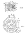
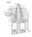
- safety valve has been described as an insertable component in a hydraulic fluid line forming part of a system to be protected, this can be incorporated in any part of conventional equipment for which it would be useful, such as 'A vane pump, for example, like the one shown in Figures 6 and 7, or a power steering box for vehicles, shown in Figure 8.
- the pump of FIGS. 6 and 7 is conventional in that it comprises a rotor 41 with vanes 42 rotating inside a non-cylindrical chamber formed between a central ring 43 and two flanges 44 and 45.
- This assembly forms a block (assembled by bolts 46) wedged by a stud 47 inside the suction chamber 48 provided with an inlet port 49 and located in the pump body 50 which in turn contains the bearing cage for the shaft 51 for driving the rotor 41.
- the pump body 50 is closed by the cover 52 in which the safety valve object of the invention is integrated, so that the outlet S of the valve corresponding to the discharge port 53 of the pump.
- valve corresponds to the version of FIG. 2 and its various elements, indicated in a similar manner, are perfectly identifiable.
- the outlet of the venturi 8 communicates directly with the outlet 53 of the pump via the pipe 54; the inlet thereof communicates with the pressure outlet 55 prevailing in the room 45 and the discharge chamber of the valve communicates with the suction chamber 48 of the pump via the conduits 56 and 57.
- pumps of this kind are generally fitted with a maximum pressure limiting valve in the own cover 52
- the embodiment of Figure 3 can also be incorporated porée drawer 15 of this example.
- FIG. 8 shows a power steering box 58 which comprises a cylinder 59, inside which moves a nut piston 60 which actuates, by a rack and pinion transmission, for example, the usual steering mechanism.
- the threaded axis 61 controlling the piston is driven in turn by a torsion bar 62 driven by the steering column 63.
- the axis 61 is secured by a key 64 of the rotary element 65 in a complementary housing of the housing. steering and which constitutes the distributor of the power steering; in this casing also rotates the core 66 of the power steering distributor integral with the steering column.
- the distributor is of the type with longitudinal grooves arranged on its circumference 67 and 68, communicating on the one hand with the oil inlet through the annular groove 69 and the slots 70 of the distributor cage and of on the other hand with the outlet orifice 71 of the power steering box 58 through the annular groove 72, the lumen 73, the interior 74 of the core 66 and the orifice 75 of the core 66.
- the safety valve is located in a cylindrical housing 76 forming part of the intake duct 77 and terminated by the supply fitting 78. An embodiment conforming to that of FIG. 5 is used for the safety valve.
Landscapes
- Engineering & Computer Science (AREA)
- Mechanical Engineering (AREA)
- Chemical & Material Sciences (AREA)
- Physics & Mathematics (AREA)
- Fluid Mechanics (AREA)
- General Engineering & Computer Science (AREA)
- Combustion & Propulsion (AREA)
- Transportation (AREA)
- Analytical Chemistry (AREA)
- Safety Valves (AREA)
Applications Claiming Priority (2)
| Application Number | Priority Date | Filing Date | Title |
|---|---|---|---|
| ES488092A ES488092A0 (es) | 1980-01-31 | 1980-01-31 | Valvula protectora de circuitos hidraulicos con senal de mando por ausencia de caudal |
| ES488092 | 1980-01-31 |
Publications (1)
| Publication Number | Publication Date |
|---|---|
| EP0033698A1 true EP0033698A1 (de) | 1981-08-12 |
Family
ID=8479705
Family Applications (1)
| Application Number | Title | Priority Date | Filing Date |
|---|---|---|---|
| EP81400149A Withdrawn EP0033698A1 (de) | 1980-01-31 | 1981-01-30 | Sicherheitsventil für hydraulische Schaltungen |
Country Status (2)
| Country | Link |
|---|---|
| EP (1) | EP0033698A1 (de) |
| ES (1) | ES488092A0 (de) |
Cited By (3)
| Publication number | Priority date | Publication date | Assignee | Title |
|---|---|---|---|---|
| EP0648931A1 (de) * | 1993-10-16 | 1995-04-19 | LuK Fahrzeug-Hydraulik GmbH & Co. KG | Ventilanordnung |
| WO1998029663A1 (en) * | 1997-01-03 | 1998-07-09 | Hobourn Automotive Limited | Flow control valve |
| WO2007051254A1 (en) * | 2005-11-04 | 2007-05-10 | Mark Andrew Fogarty | Pressure release valve, system and method of use |
Citations (1)
| Publication number | Priority date | Publication date | Assignee | Title |
|---|---|---|---|---|
| FR2417881A1 (fr) * | 1978-02-20 | 1979-09-14 | Jidosha Kiki Co | Convertisseurs electromecaniques et dispositifs de commande pour directions mecaniques les utilisant |
-
1980
- 1980-01-31 ES ES488092A patent/ES488092A0/es active Granted
-
1981
- 1981-01-30 EP EP81400149A patent/EP0033698A1/de not_active Withdrawn
Patent Citations (1)
| Publication number | Priority date | Publication date | Assignee | Title |
|---|---|---|---|---|
| FR2417881A1 (fr) * | 1978-02-20 | 1979-09-14 | Jidosha Kiki Co | Convertisseurs electromecaniques et dispositifs de commande pour directions mecaniques les utilisant |
Cited By (5)
| Publication number | Priority date | Publication date | Assignee | Title |
|---|---|---|---|---|
| EP0648931A1 (de) * | 1993-10-16 | 1995-04-19 | LuK Fahrzeug-Hydraulik GmbH & Co. KG | Ventilanordnung |
| WO1998029663A1 (en) * | 1997-01-03 | 1998-07-09 | Hobourn Automotive Limited | Flow control valve |
| US6328535B1 (en) | 1997-01-03 | 2001-12-11 | Hobourn Automative Limited | Flow control valve capable of adjusting fluid flow characteristics in accordance with a position of a valve element in a bore |
| WO2007051254A1 (en) * | 2005-11-04 | 2007-05-10 | Mark Andrew Fogarty | Pressure release valve, system and method of use |
| AU2006308808B2 (en) * | 2005-11-04 | 2013-09-19 | Mark Andrew Fogarty | Pressure release valve, system and method of use |
Also Published As
| Publication number | Publication date |
|---|---|
| ES8100453A1 (es) | 1980-11-01 |
| ES488092A0 (es) | 1980-11-01 |
Similar Documents
| Publication | Publication Date | Title |
|---|---|---|
| EP0566449B1 (de) | Kombiniertes hydraulisches Höchstlastdrück- und Drückkompensationsventil | |
| FR2497319A1 (fr) | Soupape de derivation avec alarme | |
| FR2670169A1 (fr) | Dispositif de moyens de manóoeuvre d'une installation pour vehicule automobile a direction hydraulique assistee. | |
| FR2781032A1 (fr) | Dispositif de regulation du debit d'eau avec moyen de decharge de pression | |
| WO2011048327A1 (fr) | Dispositif de transmission hydrostatique permettant un freinage ameliore | |
| EP1556619B1 (de) | Spülvorrichtung für einen kreislauf mit mindestens einem hydraulischen motor | |
| EP0033698A1 (de) | Sicherheitsventil für hydraulische Schaltungen | |
| BE1009338A3 (fr) | Vanne-pilote hydraulique. | |
| EP0459840B1 (de) | Steuereinrichtung für einen doppelt wirkenden Arbeitszylinder | |
| FR2767932A1 (fr) | Dispositif de regulation de debit volumique et systeme d'injection comportant un tel dispositif de regulation, notamment pour moteur a combustion interne | |
| EP0268521A1 (de) | Schleusenventil | |
| EP3163076B1 (de) | Hydraulische maschine mit zwei schluckvolumina und einem sicherheitsventil | |
| FR2653500A1 (fr) | Dispositif pour commander la pression dans un systeme de pression hydraulique. | |
| EP0306368B1 (de) | Druckwaage für hydraulische proportionale Wegeventile und damit ausgerüstetes hydraulisches Wegeventil | |
| EP3788283B1 (de) | Luftprobenahmesystem mit einem überdruckventil | |
| FR2620660A1 (fr) | Regulateur de niveau pour vehicule automobile | |
| EP1229245B1 (de) | Austauschvorrichtung für einen geschlossenen Kreislauf | |
| FR2892486A1 (fr) | Valve a ouverture amortie | |
| EP3329155B1 (de) | Druckbegrenzungsvorrichtung mit zwei separaten schaltventilen | |
| FR2732438A1 (fr) | Soupape a deux voies du type a detection de pression a double sens | |
| EP0537051A1 (de) | Anlage zum Pumpen von Gasen mit Pumpengeschwindigkeitsregelung | |
| FR2549166A1 (fr) | Agencement de valve pour limiter la pression dans un systeme sous pression | |
| EP0039643A1 (de) | Fluid-Sicherheitsventil | |
| EP0802327A1 (de) | Zahnradpumpe | |
| FR2489438A1 (fr) | Soupape a tiroir |
Legal Events
| Date | Code | Title | Description |
|---|---|---|---|
| PUAI | Public reference made under article 153(3) epc to a published international application that has entered the european phase |
Free format text: ORIGINAL CODE: 0009012 |
|
| 17P | Request for examination filed |
Effective date: 19810216 |
|
| AK | Designated contracting states |
Designated state(s): DE FR GB IT SE |
|
| STAA | Information on the status of an ep patent application or granted ep patent |
Free format text: STATUS: THE APPLICATION IS DEEMED TO BE WITHDRAWN |
|
| 18D | Application deemed to be withdrawn |
Effective date: 19820524 |
|
| RIN1 | Information on inventor provided before grant (corrected) |
Inventor name: BACARDIT, JUAN SIMON |