EP0032262B1 - Web controlling apparatus - Google Patents
Web controlling apparatus Download PDFInfo
- Publication number
- EP0032262B1 EP0032262B1 EP80201187A EP80201187A EP0032262B1 EP 0032262 B1 EP0032262 B1 EP 0032262B1 EP 80201187 A EP80201187 A EP 80201187A EP 80201187 A EP80201187 A EP 80201187A EP 0032262 B1 EP0032262 B1 EP 0032262B1
- Authority
- EP
- European Patent Office
- Prior art keywords
- web
- roller
- path
- turning bar
- axis
- Prior art date
- Legal status (The legal status is an assumption and is not a legal conclusion. Google has not performed a legal analysis and makes no representation as to the accuracy of the status listed.)
- Expired
Links
- 238000006073 displacement reaction Methods 0.000 claims description 24
- 230000000694 effects Effects 0.000 claims description 3
- 238000011144 upstream manufacturing Methods 0.000 claims description 3
- 230000001276 controlling effect Effects 0.000 description 9
- 238000009434 installation Methods 0.000 description 5
- 238000010586 diagram Methods 0.000 description 4
- 239000011248 coating agent Substances 0.000 description 3
- 238000000576 coating method Methods 0.000 description 3
- 230000002950 deficient Effects 0.000 description 3
- 239000000463 material Substances 0.000 description 3
- PCTMTFRHKVHKIS-BMFZQQSSSA-N (1s,3r,4e,6e,8e,10e,12e,14e,16e,18s,19r,20r,21s,25r,27r,30r,31r,33s,35r,37s,38r)-3-[(2r,3s,4s,5s,6r)-4-amino-3,5-dihydroxy-6-methyloxan-2-yl]oxy-19,25,27,30,31,33,35,37-octahydroxy-18,20,21-trimethyl-23-oxo-22,39-dioxabicyclo[33.3.1]nonatriaconta-4,6,8,10 Chemical compound C1C=C2C[C@@H](OS(O)(=O)=O)CC[C@]2(C)[C@@H]2[C@@H]1[C@@H]1CC[C@H]([C@H](C)CCCC(C)C)[C@@]1(C)CC2.O[C@H]1[C@@H](N)[C@H](O)[C@@H](C)O[C@H]1O[C@H]1/C=C/C=C/C=C/C=C/C=C/C=C/C=C/[C@H](C)[C@@H](O)[C@@H](C)[C@H](C)OC(=O)C[C@H](O)C[C@H](O)CC[C@@H](O)[C@H](O)C[C@H](O)C[C@](O)(C[C@H](O)[C@H]2C(O)=O)O[C@H]2C1 PCTMTFRHKVHKIS-BMFZQQSSSA-N 0.000 description 2
- 230000007423 decrease Effects 0.000 description 2
- 230000003247 decreasing effect Effects 0.000 description 2
- 238000001035 drying Methods 0.000 description 2
- 238000004519 manufacturing process Methods 0.000 description 2
- 230000002093 peripheral effect Effects 0.000 description 2
- 238000006748 scratching Methods 0.000 description 2
- 230000002393 scratching effect Effects 0.000 description 2
- 238000000926 separation method Methods 0.000 description 2
- VYZAMTAEIAYCRO-UHFFFAOYSA-N Chromium Chemical compound [Cr] VYZAMTAEIAYCRO-UHFFFAOYSA-N 0.000 description 1
- 230000003321 amplification Effects 0.000 description 1
- 238000013459 approach Methods 0.000 description 1
- 238000010276 construction Methods 0.000 description 1
- 230000001419 dependent effect Effects 0.000 description 1
- 210000003414 extremity Anatomy 0.000 description 1
- 238000005188 flotation Methods 0.000 description 1
- 230000004048 modification Effects 0.000 description 1
- 238000012986 modification Methods 0.000 description 1
- 238000003199 nucleic acid amplification method Methods 0.000 description 1
- -1 polyethylene terephthalate Polymers 0.000 description 1
- 229920000139 polyethylene terephthalate Polymers 0.000 description 1
- 239000005020 polyethylene terephthalate Substances 0.000 description 1
- 238000005096 rolling process Methods 0.000 description 1
- 210000001364 upper extremity Anatomy 0.000 description 1
- 238000012795 verification Methods 0.000 description 1
Images


Classifications
-
- B—PERFORMING OPERATIONS; TRANSPORTING
- B65—CONVEYING; PACKING; STORING; HANDLING THIN OR FILAMENTARY MATERIAL
- B65H—HANDLING THIN OR FILAMENTARY MATERIAL, e.g. SHEETS, WEBS, CABLES
- B65H23/00—Registering, tensioning, smoothing or guiding webs
- B65H23/02—Registering, tensioning, smoothing or guiding webs transversely
- B65H23/032—Controlling transverse register of web
- B65H23/038—Controlling transverse register of web by rollers
-
- B—PERFORMING OPERATIONS; TRANSPORTING
- B65—CONVEYING; PACKING; STORING; HANDLING THIN OR FILAMENTARY MATERIAL
- B65C—LABELLING OR TAGGING MACHINES, APPARATUS, OR PROCESSES
- B65C9/00—Details of labelling machines or apparatus
- B65C2009/0087—Details of handling backing sheets
- B65C2009/0096—Rotation of the backing sheet about its longitudinal axis by passing the backing sheet over a roller
Definitions
- the present invention relates to an apparatus for controlling the path of a travelling web as it leaves an air cushion turning bar.
- suitable configurations of air bars are used to invert moving webs, for instance in coating alleys where the web is not deflected in any lateral direction, but wherein one side of the web is coated and dried during the first half of the path through the installation, and the opposite web side is coated and dried during the second half of the web path.
- Highly polished bars that are commonly used as turning bars to change the direction of travel of a web are unsatisfactory for webs which are coated with materials subject to scratching, such as photographic film, because the web surface becomes scratched as it slides on the turning bar.
- the turning bars are air-cushion bars to prevent scratches or other damage to the film during changes in direction.
- These web turning bars are in the form of porous, slotted, perforated or otherwise permeable tubes through which air is passed to maintain a thin cushion of air between the web and the bar.
- the angle of the incoming web path to the axis of the turning bar must be equal to the angle of the outgoing path to the axis of the turning bar.
- the incoming web path is controlled by first web guiding means so that the web approaches the bar at the desired lateral position.
- a known web guiding assembly comprises a camber roller that deflects the web path over 90 degrees between a first and a second web guiding roller.
- the cambering roller is mounted for movement in a plane that makes an angle of approximately 45 degrees with respect to the incoming and outgoing web planes. This type of web guiding assembly is disclosed in US-A-2,904,333.
- this guiding means does not operate in a satisfactory way for controlling the path of webs that tend to follow a curved direction.
- Such type of webs are webs the thickness, the friction coefficient and/or the length of which differ(s) from one edge to the other, i.e. measured at different lateral positions.
- a web with a differing length is a web which, if laid flat in a plane, shows a curvature about an axis normal to said plane. There have been found curvature radii with a minimum of 1000 meters for web widths between 1.00 and 1.80 m.
- the known guiding assembly distorts the tension profile of such a curved web upon redressing the web that fallows a skewed path as it passed around the air bar.
- tension chords in the web that run in a direction that is inclined with respect to the longitudinal web axis, and because of this one or both web edges or margins may be dragged into contact with the turning bar, thereby damaging the web.
- the mentioned tension chords are also introduced into webs wherein the thickness or the friction coefficient differs from one edge of the web to the other, because upon transport of the web while the web is biased with a given longitudinal force, a transverse gradient of longitudinal tension is created.
- the present invention aims at providing an apparatus for controlling an outgoing web leaving an air cushion turning bar, which enables a satisfactory control of defective webs of the type described.
- apparatus for controlling the path of a travelling web as it leaves an air cushion turning bar comprising a freely rotatable roller, arranged on said web path as the first contact for a web leaving the turning bar, a second freely rotatable roller downstream of said first and defining between them a stretch of the path which makes an angle with-the upstream adjacent portion of said path and is generally perpendicular to the adjacent portion of said path downstream of said second roller, and means for detecting a lateral deviation by said web from its correct path
- said apparatus comprises means supporting said first roller for bodily axial displacement along a fixed axis, means mounting said second roller for pivotal movement about an axis generally perpendicular to said adjacent portion of said path downstream of said second roller, and operating means actuated in response to said detecting means for effecting axial bodily displacement of said first roller in a direction opposite to said deviation and for substantially simultaneously tilting said second roller about said axis to operate as web tension gradient control means by differentially lengthening the path of
- the controlling effect of the apparatus according to the invention is based on two operations. First, the lateral movement of the said first roller whereby correction of the lateral position of the web occurs and, second, the modification of the transverse gradient of longitudinal tension whereby a re-orientation of the position of the web on the turning bar occurs thereby to avoid the risk of dragging contact of the web with the surface of the turning bar.
- the apparatus according to the invention is particularly suited for controlling webs leaving an air cushion turning bar when the web moves at a relatively great distance from the bearing surface, that is, when the stiffness of the bearing is small.
- the stiffness of the bearing may be expressed as wherein ⁇ p stands for a pressure increase of the air that bears the web, and ⁇ h stands for a corresponding decrease of the distance between the web and the bearing surface.
- air turning bars wherein, except for the margins, a web is supported at a relatively great distance from the bearing, is disclosed in United Kingdom Patent Specification 1,484,998 filed November 29, 1973 by Agfa-Gevaert N.V. relating to an air flotation turner bar, and assigned to the same assignee of the present application.
- the web tension gradient control means is also effective to laterally displace the web.
- the apparatus comprises a second freely rotatable roller which is axially displaceable in order to laterally displace the web, said second roller being disposed as the first roller to enter into contact with the web leaving the web tension gradient control means.
- the displacements of said second roller may occur simultaneously with and be of the same magnitude as the displacements of said first roller.
- the web tension gradient control means comprises a freely rotatable roller which is arranged for bodily swinging about an axis that is parallel with the plane of the web section between said first axially displaceable roller and said web tension gradient control means.
- the dynamic friction coefficient of said first roller with respect to the web is equal to but preferably smaller than the dynamic friction coefficient with respect to the web of the roller than operates as web tension gradient control means.
- the term "dynamic” stands for the friction coefficient of a roller with respect to the web, measured at the normal transport speed of the web over the roller.
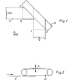
- the direction of travel of a moving web 11 is changed over 90° by folding the web over an air turning bar 12.
- the angle of the incoming web path to the axis of the turning bar equals the angle of the outgoing web path to the axis of the turning bar, namely 45°.
- the air turning bar may be a cylindrical, hollow body, the turning surface of which is provided with a multiplicity of perforations, not shown, through which the air flows to provide an air cushion for the web 11 in the conventional . manner.
- Other configurations of air turning bars may be used equally well.
- the air to provide the air cushion may be supplied to the ends of the turning bar, as is conventional in the art.
- the distance between the web and the bearing surface of the turning bar is indicated by h.
- the length of web portion which has been indicated by ABCD in Fig. 1, is shown in unfolded condition in Fig. 3.
- the drawing illustrates a perfectly straight web.
- the hatched portion EFGH is the area over which the web is supported on the turning bar.
- T the longitudinal tension in the web in N/m
- p the air pressure in Pascal of the bearing at the position of the web
- r the radius of curvature of the web around the bearing in m. Since the variations of p are small for distance variations within certain limits, r is almost directly proportional to T so that tension chords, i.e. an increase in longitudinal tension, cause an increase of r, which means a lesser curvature of the web.
- tension chords i.e. an increase in longitudinal tension
- r which means a lesser curvature of the web.
- FIG. 4 wherein the positions of two longitudinal web zones between points K and L at different longitudinal web tensions have been illustrated.
- a first web zone 11 at a normal longitudinal tension has a curvature that is concentric with respect to the cylindrical bearing surface 12, and that is indicated by the curvature radius r,.
- a second web zone 11' is at a greater longitudinal tension than zone 11, and so has a lesser curvature than zone 11, as indicated by the curvature radius r 2 .
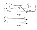
- FIG. 6 An approximate illustration of the re-orientation of a curved web over an air turning bar, as it is performed by an apparatus in accordance with the present invention, is illustrated in Fig. 6 for a web section that is exaggeratedly curved for the sake of illustration. It may be seen that the web is not pulled or redressed "straight" but that its inherent curvature is maintained. The web is only slightly re-oriented so that the tangent 18 to its longitudinal axis 19 at approximately the centerpoint 20 of its supported area E'F'G'H' on the turning bar, runs approximately parallel with the longitudinal direction of a perfectly straight web illustrated in drawn lines.
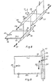
- Fig. 8 which illustrates diagrammatically an apparatus according to the invention for controlling a web 22 leaving an air turning bar and advancing in the direction of the arrow 23, the apparatus comprises freely rotatable and parallel rollers 24, 25 and 26 that are arranged for axial displacement as indicated by the arrows 27, 28 and 29.
- the roller 25 is further arranged so that it may swing about an axis at an angle to it, such as the vertical axis 31 illustrated, so that the opposite extremities of the roller may swing in a horizontal plane. It should be noted that the axial displacement of the roller 25 is illustrated diagrammatically only.
- the shaft of roller 25 need not necessarily be able to carry out a sliding movement in its bearings, but the axial component of motion of the roller 25 may also result from the swinging of the roller 25 about a vertical axis that is well remote of the axis of the roller..
- the roller 25 is so located with respect to the roller 24 that the web 22 is deflected over an angle of about 90 degrees around the roller 24. Said angle is not critical and may be smaller or larger than 90 degrees. In the rest position of the apparatus the roller 25 runs parallel with the rollers 24 and 26.
- the edge sensor 34 will control the mechanism (not shown) that controls the position of the rollers, in such a way that the three rollers 24, 25 and 26 are displaced towards the right side (R) of the moving web, as indicated by the arrows 35, 36 and 37 in Fig. 8, and the roller 25 is swung in the direction of the arrow 38 so as to increase the web tension at the right side (R) of the web by increasing the length of the web path between the rollers 24 and 26 at said right-hand position.
- the axial displacement of the rollers 24, 25 and 26 causes an instant displacement of the curved web in the direction of its right side (R) so that the right web edge remains within the sensing area of the edge sensor 34.
- the roller 25 causes a transverse gradient of longitudinal tension in the web, the greater tension being situated at the right side of the web 22, so that the said web side is pulled at a greater rate than the left side (L), whereby the web will maintain a curved position.
- Fig. 9 which is a plan view of the entering web section of Fig. 8, it may be seen that the front edge 40, i.e. a line normal to the longitudinal centerline of the curved web 33, makes an angle a with respect to the axis 41 of the roller 24.
- a web engaging a roller in the illustrated way would hitherto displaced on the roller 24 in the direction of the right side of the roller, i.e. in the direction of the arrow 30, until the front edge 40 of the web would run parallel with the roller axis 41.
- the mentioned treatment would destroy the satisfactory guidance of a "curved" web about an air turning bar as diagonal tension chords would be introduced into suchlike web as described already.
- the increased longitudinal tension at the right side of the web in accordance with the invention causes a curving tendency of the web from the right towards the left side, so that the natural curvature of the web is maintained and a lateral component of force is created in the web which tends to displace the web on the roller 24 towards the left direction, i.e. according to the arrow 32 of Fig. 9.
- Said mentioned component of force causes a continuous lateral slipping of the web on the roller 24 and thus balances the force which is created by the rolling of the web on the roller at a certain angle and which tends to displace the webs in the direction of the arrow 30 towards the right side (R).
- This balance of lateral forces has the result that a curved web continues to follow a curved path, as illustrated by the position in broken lines 33, the right lateral edge of the web being maintained at the position at the place of the edge sensor 34.
- the angular movement of the roller 25 in order to control the tension gradient over the web may occur by pivotation about other axes than the axis 31 illustrated.
- the roller may be arranged for bodily angular displacement by providing the roller with bearings in such a way that they carry out axial as well as radial displacements with respect to the roller so that an imaginary axis of pivotation of the roller is obtained.
- Figs. 10 to 12 illustrate constructional details of a practical embodiment of apparatus which operates according to the principles described with reference to Figs. 8 and 9, and which yields very satisfactory results in practice.
- the apparatus comprises a stationary frame 43 having uprights 44 and 46 interconnected by horizontal struts 45 and carrying three horizontal beams 47, 48 and 49, and a horizontally movable frame 50 having uprights 51 and 53 interconnected by horizontal struts 52 and carrying three horizontal beams 54, 55 and 56.
- the movable frame 50 is journalled on roller bearings 57 and 58 for to and fro movement in a direction which is transverse with respect to the path of a web moving through the apparatus, i.e. a direction according to the arrow 59 in Fig. 11. Movement of the frame 50 is controlled by an air motor 60 which connects an upright 51 of the movable frame 50 with an upright 44 of the stationary frame 43.
- the apparatus comprises three freely rotatable rollers.
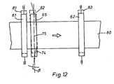
- the rollers 61 and 62 which are journalled in parallel in bearings 63 and 64 mounted on the beams 56 and 54 of the movable frame 50, and the roller 65 which is journalled in bearings 66 mounted on a further horizontal beam 67.
- the rollers 61 and 62 are smooth-surfaced rollers having a high gloss chrome finish as usual in the art, whereas the roller 65 is a chrome-plated roller the peripheral surface of which has been provided with a spiral groove 111 thereby to promote the escape of air that is dragged by the moving web in the nip between the web and the roller.
- the dynamic friction coefficient between the rollers 61 and 62 versus the web 80 is smaller than the dynamic friction coefficient between the roller 65 and the web.
- the beam 67 is arranged as follows for displacement in a horizontal plane. Each end of the beam is provided with an angled plate 68 which is pivotably fitted by means of a pin 69 to a slide member 70. Each slide member 70 is slidably supported on two parallel rods 71 and 72 that are mounted in a bracket 73. The two brackets 73 (one for each end of the roller 65) are mounted with their longitudinal axis 74 at a small inclination f3 to the longitudinal direction of the beam 47, so that the rods 71 and 72 make an angle f3 with respect to the transverse direction 75 of the apparatus as illustrated diagrammatically in Fig. 12.
- FIG. 12 is a diagrammatic plan view of the rollers of the apparatus of Figs. 10 and 11, wherein there has been left some horizontal separation between the rollers 61 and 65 for the sake of clarity.
- the beam 67 is connected with the movable frame 50 through a rod 76 which is pivotally fitted to the beam 67 at the point 77 and likewise pivotally fitted to the frame 50 at the point 78 of the strut 52.
- the rod 76 extends almost horizontally over the full width of the apparatus as indicated in Fig. 11, and therefore the position of the rod in Fig. 10 should be not misinterpreted.
- the beam 67 is arranged to have the roller 65 run parallel with the rollers 61 and 62, when the apparatus is in its rest or inactive position.
- an edge sensor 79 detects a deviation of the web edge from the correct position, then an error signal is produced that controls after suitable amplification the motor 60 in such a way that the movable frame 50 is moved in that direction wherein the rollers 61 and 62 laterally displace the web until the web edge has resumed the correct position in respect of the edge sensor 79.
- the rollers 61 and 62 carry out a truly axial displacement
- the roller 65 undergoes also an angular displacement in addition to the axial displacement. This additional angular displacement is a direct consequence of the inclined mounting of the guides for the roller bearings.
- the roller 65 is a cambering roller known in the art as a Kamberoller (Registered Trademark).
- the dis- stance between the rollers 65 and 62 will be increased at the upper ends of the rollers and correspondingly decreased at the lower ends of the rollers according to Fig. 12, so that a corresponding lateral gradient of longitudinal tension is established in the web, the greater tension being at the upper web edge in the illustration of Fig. 12.
- the following data illustrate the apparatus that was successfully used for the control of the path of a web over an air turning bar that deflected the web path over 90°.
- the edge sensor 79 may have other positions that the illustrated one.
- One alternative position is the position 81 illustrated in broken lines in Fig. 10.
- Other possible positions are further towards the roller 65, between the rollers 65 and 62, and even downstream of the roller 62.
- a sensor position most clost to the roller 61 usually gives best results.
- the rotation of the rollers may raise problems when relatively high web speeds, for instance web speeds higher than 80 m.s-1, are applied. Air which is entrained by the web between the rollers and the wrapped web area, causes slipping of the rollers and decreases the efficiency of the apparatus.
- Known measures such as increasing the friction coefficient of the rollers, providing the peripheral surface of the rollers with a plurality of axial or helicoidal grooves, etc., may be taken.
- the roller 65 deserves attention for the application of such measures. Consequently it is indeed desirable that the coefficient of friction of the web tension controlling roller 65 is at least equal to and preferably higher than the coefficient of friction of the web position controlling rollers and, above all, of the roller 61. As a matter of fact, it is necessary that the web should be capable of continuously laterally slipping on the roller 61 as mentioned already. Such lateral slipping is not desired on the roller 65 to perform the satisfactory operation of the apparatus.
- FIG. 13 is the first half of the installation and Fig. 14 the second half thereof, the dash and dot line 112 being the common section line of the web in both Figs.
- a web 113 is passed over rollers 84 and 85 to a conventional apparatus for steering the lateral web position at an edge sensor 110.
- the steering apparatus comprises three parallel rollers 86, 87 and 88 that are swingable as one unit about a vertical axis 89.
- the direction of web travel is changed over 90° by a first air turning bar 90.
- the position of the web on the air turning bar 90 is controlled by the apparatus according to the invention that comprises the rollers 91, 92 and 93.
- Rollers 91 and 93 are axially displaceable whereas roller 92 is axially and angularly displaceable as illustrated in Figs. 10 and 11.
- An edge sensor 94 controls the operation of the rollers 91 to 93.
- the web is then passed over rollers 95 to 101 to a second air turning bar 102 that changes the direction of web travel a second time over 90°.
- the former upper side of the web has now become the lower side. This may most easily be followed by considering the interchanging of the position of both web edges.
- One web edge has been doubled by a broken line 114 for the ease of verification. This line has been shown at both sides of the web.
- the position of the web on the second air turning bar 102. is controlled by a second apparatus in accordance with the invention, and which comprises rollers 103, 104 and 105 that operate in the same way as do the rollers 91, 92 and 93, and that are controlled by an edge sensor 106.
- the web is finally pulled over a freely. rotatable roller 107 with fixed axis, for transport to a further destination.
- the lateral position of the outgoing web at the arrow 108 coincides with the position of the incoming web at 109.
- rollers 95 to 99 The purpose of the rollers 95 to 99 is to provide a lateral constraint for the web whereby the possible effect of the steering of one air turning bar on the other bar may be isolated. Said additional constraint is not indispensable. Its necessity is dependent on the web curvature that may be expected, the web tension, the configuration of the air turning bars, etc.
- the apparatus according to the invention may as well be used for the control of webs passing over so-called "straight" air cushion bars whereby the direction of travel of a web is not changed to a lateral direction but only in a plane normal to the plane of the incoming web section and comprising the longitudinal axis of the web.
- straight air cushion bars whereby the direction of travel of a web is not changed to a lateral direction but only in a plane normal to the plane of the incoming web section and comprising the longitudinal axis of the web.
- the problems met with the guidance of defective webs as described hereinbefore are less with such straight air cushion turning bars than they are with the described bars for laterally changing the direction of travel of a web.
- the means for web tension gradient control may be rollers other than the described cambering roller.
- a roller comprising a flexible axle and a flexural tubular sleeve may be used. Control of the position of one or both ends of the flexible axle may change the length of the web path between the first and the second axially displaceable roller for laterally displacing the web.
- Another alternative solution comprises the use of a roller with a rigid shaft and an inflatable mantle so that the diameter thereof may be progressively varied from one end of the roller to the other end.
Landscapes
- Registering, Tensioning, Guiding Webs, And Rollers Therefor (AREA)
Applications Claiming Priority (2)
| Application Number | Priority Date | Filing Date | Title |
|---|---|---|---|
| GB8000093 | 1980-01-02 | ||
| GB8000093 | 1980-01-02 |
Publications (3)
| Publication Number | Publication Date |
|---|---|
| EP0032262A2 EP0032262A2 (en) | 1981-07-22 |
| EP0032262A3 EP0032262A3 (en) | 1981-08-05 |
| EP0032262B1 true EP0032262B1 (en) | 1984-04-18 |
Family
ID=10510407
Family Applications (1)
| Application Number | Title | Priority Date | Filing Date |
|---|---|---|---|
| EP80201187A Expired EP0032262B1 (en) | 1980-01-02 | 1980-12-10 | Web controlling apparatus |
Country Status (5)
| Country | Link |
|---|---|
| US (1) | US4385716A (enExample) |
| EP (1) | EP0032262B1 (enExample) |
| JP (1) | JPS56103046A (enExample) |
| CA (1) | CA1151689A (enExample) |
| DE (1) | DE3067590D1 (enExample) |
Families Citing this family (22)
| Publication number | Priority date | Publication date | Assignee | Title |
|---|---|---|---|---|
| DE3420667A1 (de) * | 1984-06-02 | 1985-12-05 | Süka Süddeutsche Spezialdruckerei Hermann Jung GmbH, 7512 Rheinstetten | Zufuehrvorrichtung fuer endlospapier zu einem schnelldrucker |
| US4617008A (en) * | 1984-09-20 | 1986-10-14 | Mobil Oil Corporation | Method and apparatus for forming hems in superposed pliable panels |
| US4627584A (en) * | 1984-09-20 | 1986-12-09 | Mobil Oil Corporation | Method and apparatus for feeding a plastic ribbon |
| US4624734A (en) * | 1984-10-19 | 1986-11-25 | New Jersey Machine Inc. | Label dispenser with articulated guide |
| EP0437204B1 (en) * | 1990-01-11 | 1994-09-14 | Canon Kabushiki Kaisha | Lateral shift control for endless belt and fixing apparatus using same |
| US5813337A (en) * | 1996-06-05 | 1998-09-29 | Quad/Tech, Inc. | Closed-loop printing control system |
| US6035259A (en) * | 1997-06-18 | 2000-03-07 | Eastman Kodak Company | Web material camber measurement apparatus and method |
| US5826818A (en) * | 1997-06-30 | 1998-10-27 | Kvaerner U.S. Inc. | Compact strip processing facility |
| DE19728207A1 (de) * | 1997-07-02 | 1999-01-07 | Wifag Maschf | Wendeturmanordnung |
| AU703647B1 (en) * | 1998-06-16 | 1999-03-25 | Qi Press Controls Holding Bv | Device to compensate for print misregister due to paper distortion on web offset printing presses |
| US6754033B1 (en) * | 2000-08-16 | 2004-06-22 | International Business Machines Corporation | Tape surface constraint of lateral transients |
| EP1209080A1 (en) * | 2000-11-23 | 2002-05-29 | SARONG S.p.A. | Process and device for tilting a continuous strip of containers |
| PT2159056E (pt) * | 2008-08-27 | 2014-03-11 | Rpc Bebo Print Patent Gmbh | Dispositivo e método para imprimir e secar filmes plásticos |
| US8593635B2 (en) * | 2008-10-01 | 2013-11-26 | Hewlett-Packard Development Company, L.P. | Camera web support |
| US8397539B2 (en) | 2010-02-18 | 2013-03-19 | Corning Incorporated | Non-contact dancer mechanisms, web isolation apparatuses and methods for using the same |
| JP5645063B2 (ja) * | 2010-07-23 | 2014-12-24 | 日本電気硝子株式会社 | ガラスフィルムの製造装置および製造方法 |
| US9199816B2 (en) | 2010-11-04 | 2015-12-01 | Corning Incorporated | Methods and apparatus for guiding flexible glass ribbons |
| KR102440164B1 (ko) * | 2015-03-27 | 2022-09-06 | 데이진 가부시키가이샤 | 복합막의 제조 방법 |
| JP6720740B2 (ja) * | 2016-07-12 | 2020-07-08 | コニカミノルタ株式会社 | 画像形成装置 |
| EP3829871A4 (en) * | 2018-10-29 | 2022-03-23 | Hewlett-Packard Development Company, L.P. | Web shift compensation |
| EP4477568A1 (en) * | 2022-02-07 | 2024-12-18 | Yushin Co., Ltd. | Belt-like plastic film conveyance method, belt-like plastic film conveyance guide, and bag-making device |
| CN117732672B (zh) * | 2024-02-21 | 2024-06-18 | 长园新能源材料研究院(广东)有限公司 | 一种并联涂布设备 |
Family Cites Families (9)
| Publication number | Priority date | Publication date | Assignee | Title |
|---|---|---|---|---|
| US2331030A (en) * | 1941-03-04 | 1943-10-05 | Hess | Web aligning apparatus |
| US2722415A (en) * | 1950-10-25 | 1955-11-01 | John Douglas Robertson | Sheet guiding apparatus |
| GB762837A (en) * | 1954-06-29 | 1956-12-05 | Goodyear Tire & Rubber | Web positioning device |
| US2904333A (en) * | 1957-03-18 | 1959-09-15 | Irwin L Fife | Turn guiding apparatus for webs |
| DE1574386C2 (de) * | 1967-03-08 | 1973-10-18 | Vits-Maschinenbau Gmbh, 4018 Langenfeld | Einrichtung zur Sicherung der seitlichen Registerhaltigkeit von mit seitlicher Versetzung ankommenden Bahnen |
| US3826416A (en) * | 1969-12-17 | 1974-07-30 | Fuji Photo Film Co Ltd | Web edge position controlling device |
| GB1338076A (en) * | 1969-12-17 | 1973-11-21 | Fuji Photo Film Co Ltd | Web feeding apparatus |
| DE2544783C3 (de) * | 1975-10-07 | 1979-08-23 | Gwd Steuerungsgeraete Gmbh, 4800 Bielefeld | Positionsregelung für eine sich bewegende Bahn |
| US4069959A (en) * | 1976-10-27 | 1978-01-24 | Butler Automatic, Inc. | Web guide apparatus |
-
1980
- 1980-12-10 DE DE8080201187T patent/DE3067590D1/de not_active Expired
- 1980-12-10 EP EP80201187A patent/EP0032262B1/en not_active Expired
- 1980-12-19 CA CA000367192A patent/CA1151689A/en not_active Expired
- 1980-12-29 JP JP18938780A patent/JPS56103046A/ja active Granted
- 1980-12-30 US US06/221,450 patent/US4385716A/en not_active Expired - Lifetime
Also Published As
| Publication number | Publication date |
|---|---|
| US4385716A (en) | 1983-05-31 |
| JPH0138740B2 (enExample) | 1989-08-16 |
| JPS56103046A (en) | 1981-08-17 |
| EP0032262A3 (en) | 1981-08-05 |
| CA1151689A (en) | 1983-08-09 |
| EP0032262A2 (en) | 1981-07-22 |
| DE3067590D1 (en) | 1984-05-24 |
Similar Documents
| Publication | Publication Date | Title |
|---|---|---|
| EP0032262B1 (en) | Web controlling apparatus | |
| US4539072A (en) | Curl neutralizer | |
| US3679116A (en) | Web turning and guiding apparatus | |
| US3682362A (en) | Web edge sensing and guiding apparatus | |
| SE461585B (sv) | Upprullningsanordning vilken omfattar understoedjande bandorgan vilka ger den bildade rullen periferiellt stoed under upprullningen | |
| US3664561A (en) | Web guiding device | |
| US5226577A (en) | Web guide for elongated flexible web | |
| US4453659A (en) | Web guiding apparatus | |
| JPH045628B2 (enExample) | ||
| US5906305A (en) | Apparatus for the corrective positioning of a travelling web at right angles to the direction of travel | |
| US3411683A (en) | Web guiding apparatus | |
| JP2008063150A (ja) | ウエブの蛇行修正装置 | |
| US3171579A (en) | Sheet guiding and width control apparatus | |
| US3642221A (en) | Web-winding apparatus | |
| US3632030A (en) | Pneumatic fabric-guiding system | |
| US5009749A (en) | Web decurler | |
| US3330456A (en) | Universal guide | |
| US4412639A (en) | Deflector and inverter device for strips of web material | |
| US3826416A (en) | Web edge position controlling device | |
| EP0254306A2 (en) | Multi-roll web support arrangement | |
| US3100069A (en) | Adjustable wrap web guiding apparatus | |
| JPS598609B2 (ja) | ウエブアンナイソウチ | |
| JP2009046285A (ja) | ウェブ搬送方向変更機構 | |
| US2904333A (en) | Turn guiding apparatus for webs | |
| US5794317A (en) | Non-marking spreader for tubular knitted fabric |
Legal Events
| Date | Code | Title | Description |
|---|---|---|---|
| PUAI | Public reference made under article 153(3) epc to a published international application that has entered the european phase |
Free format text: ORIGINAL CODE: 0009012 |
|
| PUAL | Search report despatched |
Free format text: ORIGINAL CODE: 0009013 |
|
| AK | Designated contracting states |
Designated state(s): BE CH DE FR GB IT |
|
| AK | Designated contracting states |
Designated state(s): BE CH DE FR GB IT |
|
| 17P | Request for examination filed |
Effective date: 19820112 |
|
| ITF | It: translation for a ep patent filed | ||
| GRAA | (expected) grant |
Free format text: ORIGINAL CODE: 0009210 |
|
| AK | Designated contracting states |
Designated state(s): BE CH DE FR GB IT LI |
|
| REF | Corresponds to: |
Ref document number: 3067590 Country of ref document: DE Date of ref document: 19840524 |
|
| ET | Fr: translation filed | ||
| PLBE | No opposition filed within time limit |
Free format text: ORIGINAL CODE: 0009261 |
|
| STAA | Information on the status of an ep patent application or granted ep patent |
Free format text: STATUS: NO OPPOSITION FILED WITHIN TIME LIMIT |
|
| 26N | No opposition filed | ||
| ITTA | It: last paid annual fee | ||
| PGFP | Annual fee paid to national office [announced via postgrant information from national office to epo] |
Ref country code: BE Payment date: 19941010 Year of fee payment: 15 |
|
| PGFP | Annual fee paid to national office [announced via postgrant information from national office to epo] |
Ref country code: CH Payment date: 19950209 Year of fee payment: 15 |
|
| PGFP | Annual fee paid to national office [announced via postgrant information from national office to epo] |
Ref country code: GB Payment date: 19951020 Year of fee payment: 16 Ref country code: FR Payment date: 19951020 Year of fee payment: 16 |
|
| PGFP | Annual fee paid to national office [announced via postgrant information from national office to epo] |
Ref country code: DE Payment date: 19951025 Year of fee payment: 16 |
|
| PG25 | Lapsed in a contracting state [announced via postgrant information from national office to epo] |
Ref country code: LI Effective date: 19951231 Ref country code: CH Effective date: 19951231 Ref country code: BE Effective date: 19951231 |
|
| BERE | Be: lapsed |
Owner name: AGFA-GEVAERT N.V. Effective date: 19951231 |
|
| REG | Reference to a national code |
Ref country code: CH Ref legal event code: PL |
|
| PG25 | Lapsed in a contracting state [announced via postgrant information from national office to epo] |
Ref country code: GB Effective date: 19961210 |
|
| GBPC | Gb: european patent ceased through non-payment of renewal fee |
Effective date: 19961210 |
|
| PG25 | Lapsed in a contracting state [announced via postgrant information from national office to epo] |
Ref country code: FR Effective date: 19970829 |
|
| PG25 | Lapsed in a contracting state [announced via postgrant information from national office to epo] |
Ref country code: DE Effective date: 19971001 |
|
| REG | Reference to a national code |
Ref country code: FR Ref legal event code: ST |