EP0031500A2 - Servosystem zur Spurlagerelung eines Kopfträgers - Google Patents
Servosystem zur Spurlagerelung eines Kopfträgers Download PDFInfo
- Publication number
- EP0031500A2 EP0031500A2 EP80107634A EP80107634A EP0031500A2 EP 0031500 A2 EP0031500 A2 EP 0031500A2 EP 80107634 A EP80107634 A EP 80107634A EP 80107634 A EP80107634 A EP 80107634A EP 0031500 A2 EP0031500 A2 EP 0031500A2
- Authority
- EP
- European Patent Office
- Prior art keywords
- transducer
- servo
- signal
- track
- designations
- Prior art date
- Legal status (The legal status is an assumption and is not a legal conclusion. Google has not performed a legal analysis and makes no representation as to the accuracy of the status listed.)
- Granted
Links
Images


Classifications
-
- G—PHYSICS
- G11—INFORMATION STORAGE
- G11B—INFORMATION STORAGE BASED ON RELATIVE MOVEMENT BETWEEN RECORD CARRIER AND TRANSDUCER
- G11B5/00—Recording by magnetisation or demagnetisation of a record carrier; Reproducing by magnetic means; Record carriers therefor
- G11B5/48—Disposition or mounting of heads or head supports relative to record carriers ; arrangements of heads, e.g. for scanning the record carrier to increase the relative speed
- G11B5/58—Disposition or mounting of heads or head supports relative to record carriers ; arrangements of heads, e.g. for scanning the record carrier to increase the relative speed with provision for moving the head for the purpose of maintaining alignment of the head relative to the record carrier during transducing operation, e.g. to compensate for surface irregularities of the latter or for track following
- G11B5/596—Disposition or mounting of heads or head supports relative to record carriers ; arrangements of heads, e.g. for scanning the record carrier to increase the relative speed with provision for moving the head for the purpose of maintaining alignment of the head relative to the record carrier during transducing operation, e.g. to compensate for surface irregularities of the latter or for track following for track following on disks
- G11B5/59633—Servo formatting
- G11B5/59655—Sector, sample or burst servo format
-
- G—PHYSICS
- G11—INFORMATION STORAGE
- G11B—INFORMATION STORAGE BASED ON RELATIVE MOVEMENT BETWEEN RECORD CARRIER AND TRANSDUCER
- G11B5/00—Recording by magnetisation or demagnetisation of a record carrier; Reproducing by magnetic means; Record carriers therefor
- G11B5/48—Disposition or mounting of heads or head supports relative to record carriers ; arrangements of heads, e.g. for scanning the record carrier to increase the relative speed
- G11B5/58—Disposition or mounting of heads or head supports relative to record carriers ; arrangements of heads, e.g. for scanning the record carrier to increase the relative speed with provision for moving the head for the purpose of maintaining alignment of the head relative to the record carrier during transducing operation, e.g. to compensate for surface irregularities of the latter or for track following
- G11B5/596—Disposition or mounting of heads or head supports relative to record carriers ; arrangements of heads, e.g. for scanning the record carrier to increase the relative speed with provision for moving the head for the purpose of maintaining alignment of the head relative to the record carrier during transducing operation, e.g. to compensate for surface irregularities of the latter or for track following for track following on disks
- G11B5/59633—Servo formatting
- G11B5/5965—Embedded servo format
Definitions
- the invention relates to a servo system for centering a transducer over a path, and is particularly but not exclusively applicable to magnetic disks for the recording and reproduction of data.
- the transducer corresponds with a data track that is either detected by this transducer or a transducer mechanically connected with and movable with this transducer, so that the data may be read from the data track (or fresh data may be written on this data track) in this position of the transducer.
- the tri-bit servo pattern is disclosed in the IBM Technical Disclosure Bulletin publication of April 1974, pages 3757-3759 and comprises magnetic patterns, portions or segments encoded on a magnetic disk in concentric tracks.
- the magnetic segments are in pairs of long and short segments, and the ends of long and short segments on alternate tracks are disposed on the same radius or radial line of the disk.
- the long and short segments are magnetically encoded the same along this radius or radial line and thus provide magnetic flux reversals circularly on each track.
- a servo transducer positioned over the tracks experiences flux reversals as each junction between magnetic segments passes the transducer gap, and the polarity and amplitude of the resulting pulse vary with the polarity and amplitude of the flux reversal causing them.
- the circuitry connected with the servo transducer and producing a position error signal generally includes peak detection circuits for determining the relative amplitudes of the peaks of the signal from the servo transducer and in one way or another comparing these amplitudes so as to determine whether the servo transducer (and the data transducer if this is a separate transducer) is aligned with the desired data track.
- peak detection circuits for determining the relative amplitudes of the peaks of the signal from the servo transducer and in one way or another comparing these amplitudes so as to determine whether the servo transducer (and the data transducer if this is a separate transducer) is aligned with the desired data track.
- these peaks should be spaced time-wise with disk rotation so that they do not interfere with each other and so that the leading and trailing ends of the peaks do not overlap adjacent peaks.
- a relatively wide band width is required to accommodate many harmonics of the fundamental frequency detected by the servo
- the rotatable data storage apparatus disclosed in U. S. patent 3,936,876 is an example of a magnetic track following servo system utilizing the tri-bit servo pattern.
- a separate servo transducer effective on the lower side of a magnetic disk is used; and the servo transducer is mechanically coupled with a pair of data transducers effective on the upper surface of the disk.
- the servo circuitry disclosed in this patent includes a pre-amplifier receiving the servo signals from the servo transducer and supplying an output to a detector.
- the detector provides a position error signal the amplitude of which is dependent on the distance that the servo transducer is off of a guide path, and the detector includes a pair of demodulators that are responsive to the peaks of signals supplied from the servo transducer so as to provide the position error signal at the output of the detector.
- This position error signal is used by means of a compensator and a driver circuit so as to energize a voice coil which moves the servo transducer to correct its position.
- Peak detection of a servo transducer output signal has also been used in connection with other servo patterns and in particular with a pattern in which similarly magnetized servo track portions of adjacent tracks are not in edge alignment radially of the disk and in particular in which short and long similarly magnetized servo track portions are centrally disposed radially of the disk. Since peak detection is used, the same disadvantages apply, namely, unduly wide band width with a great number of harmonics required to produce the distinctive signal peaks and a relatively slow sampling rate.
- One such system is disclosed in U. S. patent 3,534,344, and the position information is recorded in successive tracks on a separately dedicated disk.
- Each of the servo tracks contains the spaced set of paired flux reversals, and the sets of flux reversals repeat every other track so that one separately identifiable set of flux reversals will occur in the odd tracks and another separately identifiable set of flux reversals occurs in the even tracks. These are sensed by the servo transducer; and, when the servo transducer is exactly centred over adjacent odd or even tracks, the signal strength from the two adjacent tracks are equal.
- the peaks of the output signal of the servo transducer caused by adjacent tracks are integrated, and the integrated wave forms are then rectified by half-wave rectifiers and are then applied to peak detectors. Due to the use of these peak detectors, the peaks of the output signal of the transducer must be well spaced as above noted.
- the transducer positioning systems of U. S. patents 3,893,180 and 3,959,820 also use the same servo pattern as is used by the apparatus of U. S. patent 3,534,344 in which similarly magnetized long and short servo track portions of adjacent servo tracks are centrally located with respect to each other.
- the signal strength of each servo output response is first identified, and the peak amplitudes of the responses are thereafter separately measured and separate signals are produced indicative of the major peak amplitudes. The separate signals are thereafter combined so as to indicate whether the signal strength of either response dominates over the other.
- the servo responsive system of patent 3,959,820 analyzes the output servo signal and defines two separate data tracks for each and every individual track of position information traversed.
- the circuitry of this patent uses a positive peak detector and a negative peak detector for analyzing the servo transducer output signal.
- the same disabilities apply to the structures of these two patents, since they both rely on peak detection for determining the position of the servo transducer.
- the invention provides a servo system for centering a transducer over a predetermined path, comprising: first and second servo tracks extending along opposite sides of the path respectively and each comprising a plurality of designations with junctions therebetween detectable by the transducer and arranged to provide a transducer output signal whose characteristics vary in dependence upon the lateral offset of the transducer from the path, such output signal characteristics providing an indication both of the degree and direction of the lateral offset; circuit means responsive to the transducer output signal to provide a position error signal (P.E.S.) indicating the lateral position of the transducer with respect to the path; and transducer positioning means responsive to the position error signal to reduce any lateral offset of the transducer from the path; characterised in that:
- the servo system uses magnetic servo encoding of a type in which alternate short and long magnetic segments are centred from track to track, an automatic gain control amplifier for providing an analog output signal of the type picked up by a servo transducer on the servo encoding with the fundamental being constant, a squaring and frequency doubler circuit for producing a uniform frequency square wave signal of double the frequency of the fundamental of the analog signal picked up by the transducer, a filter connected with the amplifier for producing an analog double frequency signal based on the analog signal produced by the amplifier, a synchronous detector functioning as a multiplier for multiplying the double frequency square wave signal with the analog double frequency signal for thus producing a pulsating position error signal and filtering means for averaging the pulsating position error signal to provide a steady state position error signal for any particular position of the transducer over a pair of adjacent servo tracks.
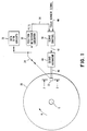
- the disk 20 is of the buried servo information type disclosed in U. S. patent 3,404,392, for example, and comprises two magnetic layers of different coercivities, an upper data layer 24 and a lower servo layer 26 which are placed on a substrate 28.
- the disk may be of the flexible type with the substrate 28 in particular being flexible, and in this connection the substrate 28 may be of polyethylene terephthalate (Mylar) of about .075 mm thickness as is disclosed in U. S. patent 4,038,693.
- Mylar polyethylene terephthalate
- the disk 20 may or may not be enclosed in a more rigid jacket as is disclosed in this patent.
- the transducer positioning system shown in FIG. 1 comprises data read/write circuits 30 and position detection circuitry 32 connected by means of line 34 with the transducer 22.
- the line 34 as shown in FIG. 1 is adapted to transmit information in both directions.
- the position detection circuitry 32 is connected by means of a line 36, which carries a position error signal (PES) 37 shown in FIG. 5, to a servo control 38.
- PES position error signal
- the line 36 constitutes an input to the servo control 38, and the servo control 38 has a second input line 40 which carries a track number signal for accessing the transducer 22 on the disk 20.
- the servo control 38 has an output line 42 connecting it to a servo actuator 44, and the servo actuator 44 has a mechanical link 46 connecting the servo actuator 44 mechanically with the transducer 22 so as to move the transducer 22 radially across the disk 20 in one direction or the other in accordance with the manner in which the servo actuator 44 is energized.
- the data R/W circuits 30, the servo control 38 and the servo actuator 44 may be of conventional design, and therefore no further detailed description of these units will be given.
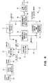
- the position detection circuitry 32 is shown in detail in FIG. 4.
- the general shape of the position error signal 37 on line 36 and shown in FIG. 5 is conventional; however, its generation by the position detection circuitry 32 will be hereinafter described.
- the transducer 22 is conventional and comprises a magnetic core 48 having a gap 50 therein and having a winding 52 wound thereon (see FIG. 2).
- the winding 52 terminates on the line 34.
- the servo layer 26 is magnetically encoded with servo tracks 1, 2, 3, 4, etc.
- the data layer 24 is magnetically encoded with data tracks a, b, c, etc. (see FIGs. 3, 6A and 6B). All of these tracks are concentric with the centre C of the disk 20.
- the servo tracks 1, 2, 3, 4, etc. have boundaries 54a, 54b, 54c, etc. (which may be considered transducer guide paths) between them, and each of the data tracks a, b, c, etc. have centre lines z.
- the servo tracks 1, 2, 3, 4, etc. are staggered radially of the disk 20 with respect to the data tracks a, b, c, etc., and the servo track boundaries 54a, 54b, etc.
- Each of the data tracks a, b, c, etc. when encoded with data has a series of closely spaced radially extending magnetic transitions 56.
- the outermost servo track 1 is formed by relatively short designations in the form of short magnetized segments 58 and relatively long designations in the form of long magnetized segments 60 that are disposed alternately along the track 1. All of the segments 58 are magnetized in a common direction opposite to the direction A), and all of the segments 60 are magnetized in the opposite direction (same as the direction A). Thus the segments 58 and 60 form positive magnetic transitions 62 and negative magnetic transitions 64 which occur alternately along the track 1 and extend radially of the disk 20.
- the alternate odd tracks 3, 5, 7, etc. all are formed in a similar manner to the track 1; i.e. they have alternating short and long oppositely magnetized segments 58 and 60 and alternating positive and negative magnetic transitions 62 and 64. Furthermore, these alternative odd tracks are in radial alignment, i.e. the transitions 62 and 64 line up in the radial direction of the disk.
- the servo track 2 lying between the similarly formed and radially aligned servo tracks 1 and 3 is formed by short designations in the form of short magnetized segments 66 alternating with long designations in the form of long magnetized segments 68.
- the short segments 66 are magnetized in a direction opposite to the direction of magnetization of the short segments 58
- the long segments 68 are magnetized in a direction opposite to the direction of magnetization of the long segments 60.
- the segments 66 and 68 thus have alternating positive and negative radial magnetic transitions 62 and 64 between them as shown in FIGs. 3 and 6.
- Each of the short segments 66 of the servo track 2 is centrally located with respect to a long segment 60 of the servo track 1 at the boundary 54a between the two servo tracks and radially of the disk 20, and each of the short segments 58 of the servo track 1 is centrally located with respect to one of the long segments 68 of the servo track 2 at the boundary 54a and radially of the disk 20 (see FIG. 3).
- the servo tracks 1 and 2 will produce at the boundary 54a consecutively two positive magnetic transitions 62 followed by two negative transitions 64 on any given radius of the disk 20.
- the alternate even tracks 4, 6, 8, etc. are formed with alternating magnetic segments 66 and 68 in a similar manner to the track 2 and all the even tracks are in radial alignment as shown.
- the alternate tracks 3, 5, 7, etc. produce the same sequence of transitions at the same angular positions as does the track 1, and the alternate tracks 4, 6, 8 etc. produce the same sequence of transitions at the same angular positions as servo track 2.
- the long segments 60 may be three times as long as the short segments 58 in the tracks 1, 3, 5, 7, etc.; and the long segments 68 may be three times as long as the short segments 66 in the tracks 2, 4, 6, etc.
- the edges of each of the short segments 58 are located on the same radial lines of the disk 20 as the edges of corresponding short segments in the other odd tracks, and the same is true of the edges of the short segments 66 in the even tracks.
- the position detection circuitry 32 shown in FIG. 4 comprises a low pass servo filter 70, an automatic gain control amplifier 72, a fundamental (f) bandpass filter 74, an envelope detector 76, a second harmonic (2f) band pass filter 77, a squaring circuit and frequency doubler 78, a synchronous detector and multiplier 80, and a low pass filter 82.
- the servo filter 70 has the line 34 as an input and provides a servo signal output on line 84 which constitutes an input to the AGC amplifier 72.
- the AGC amplifier 72 has two additional inputs which are the lines 86 and 88.
- the line 86 is supplied with a DC reference voltage so that the amplifier 72 may function as intended, and the line 88 constitutes an output of the envelope detector 76 and carries an "amplitude of fundamental" signal.
- the amplifier 72 has the line 90 as an output which carries an "analog f + 2f" signal, and the line 90 constitutes inputs to the filters 74 and 77.
- a line 91 carrying the signal "analog 2f” connects the output of the filter 77 with the synchronous detector 80.
- the filter 74 has the output line 92 carrying a signal "analog f", and the line 92 constitutes an input to the squaring circuit 78 and envelope detector 76.
- the squaring circuit 78 has the line 94 as an output which carries a signal "reference, 2f square wave", and the line 94 constitutes a second input to the synchronous detector 80.
- a line 96 constitutes the output of the synchronous detector 80 and an input to the low pass filter 82.
- the data on the data tracks a, b, c, etc. in the form of the transitions 56 may be written using the conventional data R/W circuits 30.
- the data is transmitted from the circuit 30 through the line 34 to the transducer 22, and the encoding of the data is accomplished as the disk 20 is driven in direction A.
- the servo information in the form of the magnetized segments 58, 60, 66 and 68 has been previously written on the disk 20 using any suitable magnetic encoder means, and the position detection circuitry 32 is used as will be described to cause the transducer gap 50 to be exactly in alignment or centred with the data tracks a, b, c, etc. as the data is written on these tracks.
- the position detection circuitry 32 assures that the transducer gap 50 is exactly centred on the data tracks a, b, c, etc. when a reading of the data is accomplished.
- the data information passes through the line 34 to the circuits 30 for any suitable recording or other usage.
- the position detection circuitry 32 provides a position error signal 37 on line 36 that is triangular and varies in magnitude and sign depending on the positioning of the gap 50 with respect to boundaries 54a, 54b, 54c, etc. between adjacent servo tracks corresponding to overlying data tracks a, b, c, etc.
- the gap 50 is exactly positioned over the data track a for example when it is centred on the corresponding boundary 54a between servo tracks 1 and 2.
- the same is true with respect to the boundaries 54b, 54c, etc. and the respective data tracks b, c, etc.
- the position error signal 37 is zero when the transducer 22 and its gap 50 is centred on the boundary 54a and is zero when the transducer and gap are centred on the boundary 54b.
- the position error signal 37 is maximum when the transducer 22 and its gap 50 are centred over servo track 1 and over servo track 2, but the position error signal 37 is at a positive value in the former case and is a negative value in the latter case.
- the position error signal increases and decreases in exactly the same manner when the transducer 22 and the gap 50 move radially across the disk 50 so as to traverse successive servo track boundaries 54c, etc. and successive data tracks c, etc.
- the position error signal 37 in changing as shown in FIG. 5 is conventional and operates in a conventional manner on the servo control 38 and servo actuator 44 so as to move the transducer 22 and gap 50 into substantially exact alignment with a selected one of the boundaries 54a, 54b, 54c, etc. and corresponding data tracks a, b, c, etc. when the position error signal has a finite voltage level.
- the transducer 22 and gap 50 are exactly centred on one of the boundaries 54a, 54b, 54c, etc. and on the corresponding one of the data tracks a, b, c, etc., and the transducer 22 is then in position to either read or write data on one of the data tracks a, b, c, etc.
- a track number signal is supplied on line 40 to the servo control 38, and the servo control 38 functions as is well known and conventional to accomplish the positioning of the transducer 22 approximately on the data track and servo track boundary desired.
- the position detection circuitry is then effective to exactly align the transducer 22 and its gap 50 with the boundary and data track.
- the position detection circuitry 32 produces the position error signal 37 shown in FIG. 5 which is effective to move the transducer 22 in one direction or the other to centre the transducer on the desired data track particularly by utilizing the second harmonic of the fundamental signal produced by the transducer 22 when it is not exactly centred on the desired data track and servo track boundary.
- the line 34 carries a data signal from one or more of the data tracks a, b, c, etc. and also carries a servo signal generated by the tracks 1, 2, 3, etc.
- the data transitions 56 are very much more closely spaced than are the servo transitions 62 and 64; the data signal is at a much higher frequency than the servo signal; and the servo filter 70 is provided for blocking such high frequency data signals.
- the filter 70 will function in the same manner to block any such high frequency data signals from the circuitry 32.
- the data is purposely coded in such a way so that it does not have the low frequency content that would be admitted into the circuitry 32, and only the fundamental and second harmonic servo signals of low frequency are used by the circuitry 32.
- the servo filter 70 thus assures that only the low frequency servo signals enter the circuitry 32.
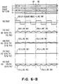
- the automatic gain control amplifier 72 functioning with the fundamental filter 74 and the envelope detector 76 regulates the analog signal from the head 22 to provide a predetermined fixed amplitude of the fundamental 98a (see FIG. 6A).
- the output of the AGC amplifier 72 on its output line 90 is an analog signal with the amplitude of the fundamental so regulated, typical analog signals being shown at 98, 100, 102 and 104 in respect of four radially different positions of the head 22 ranging from directly over servo track 1 (topmost waveform) to directly over servo track 2 (lowermost waveform).
- FIG. 6A shows the servo tracks 1, 2, 3 and 4 in rectilinear form for simplicity, the signals 98, 100, 102 and 104 which appear on line 90 (fig. 4) caused by the magnetic transitions 62 and 64 as the disk 20 rotates in direction A.
- the amplitude of the fundamental 98a remains the same as the transducer moves from a position directly over the track 1 to a position directly over track 2.
- Each of the signals 98, 100, 102 and 104 in addition to the fundamental 98a, includes a second harmonic, these harmonics being the signals 98b, 100b, 102b and 104b.
- these second harmonic signals vary greatly, the second harmonic signal 98b being a maximum, the signal 100b being of less magnitude and the signal 102b being zero.
- the signal 104b is equal to the signal 98b but is of opposite polarity.
- the zero points of the signals 98, 100, 102 and 104 are in alignment with the centres of the segments 58, 60, 66 and 68 as the disk 20 rotates.
- the signal 98 which appears on line 90 when-the read 22 is directly over track 1 is also representative of the signal which appears on line 90 when the transducer head is centred over any other odd servo track, and similarly the signal 104 associated with the head 22 being centred over track 2 is also representative of the signal which is generated when the transducer head is centred over any other even servo track, as will be understood.
- the fundamental band pass filter 74 is so constructed that it passes only the fundamental signal 98a so that only this signal appears on line 92.
- the envelope detector 76 detects only the amplitude of the fundamental 98a and thus produces on its output line 88 a signal indicative of the amplitude of the fundamental.
- the AGC amplifier 72 is so constructed that it compares the signal on the line 88 with a fixed DC reference voltage applied to the line 86 and adjusts the gain in the amplifier 72 to force the amplitude of the fundamental 98a on line 88 to be equal to the DC voltage on line 86.
- the squaring circuit and frequency doubler 78 is so constructed that it uses the fundamental signal 98a on line 92 and provides a double frequency (2f) square wave signal 106 (see FIG. 6B) on its output line 94.
- the analog f + 2f signal on line 90 (the signals 98, 100, 102 or 104 for example) is applied onto the 2f band pass filter 77 which functions to pass only the corresponding analog second harmonic signal, such as signals 98b, 100b, 102b and 104b, to the synchronous detector 80.
- the synchronous detector 80 thus has the square wave signal 106 and the analog 2f signals 98b, 100b, 102b or 104b applied to it and is constructed and functions to multiply these two signals.
- This multiplied signal is effective on the line 96 and constitutes the pulsating positive signals 108 and 110, the zero signal 112 and the pulsating negative signal 114 (see FIG. 6B).
- These signals correspond respectively with the second harmonics 98b, 100b, 102b and 104b for the same positions of the head 22 on the servo tracks 1, 2, 3, etc. and may be considered as pulsating position error signals when the head 22 is not centred on a data track.
- the low pass filter 82 has the function of providing the low frequency averages of the varying signals 108, 110, 112 and 114, these being the average signals 108a, 110a, 112a and 114a (see FIG. 6B). These average signals 108a, 110a, l12a and 114a constitute the PES signal 37 on the line 36.
- the signal 112 and the signal 112a for the condition in which the transducer is directly over the boundary 54a are coincident and are both zero as will be seen from FIG. 6B.
- the signal 110a is of course greater than the zero signal 112a, and the signal 108a (for the condition in which the transducer is directly over track 1) is at a still higher magnitude.
- the signal 114a is equal to the signal 108a but is of opposite polarity and is for the condition in which the transducer 22 is directly over track 2.
- the PES signal 37 thus varies from a positive to a negative value as shown in FIG. 5, with the amplitudes varying as shown for the signals 108a, 110a, 112a and 114a in FIG. 6B.
- the gap 50 is positioned partially over servo track 1 and partially over servo track 2, and the results would of course be similar if the transducer gap 50 were positioned over other adjacent servo tracks.
- the fundamental and second harmonic for track 1 can be given by:
- the voltage across transducer winding 52 is: or or
- the above equation number (5) indicates that the amplitude and phase of the fundamental 98a (A l in the equation) stays constant regardless of the position that the transducer 22 has over the servo tracks.
- This equation also indicates that the phase of the second harmonic is constant and that the amplitude [(2 ⁇ -1)A2 ] of the second harmonic is directly related to the position of the head 22 over the servo tracks.
- the amplitude of the second harmonic is zero when the head 22 is positioned directly over a servo track boundary 54a, 54b, etc.
- the coefficient [(2 ⁇ -1)A 2] of the second harmonic represents the position error signal 37.
- the synchronous detector 80 acting at the frequency of the second harmonic (from line 94) generates the coefficient [(2 ⁇ -1) A 2 ], the position error signal 37.
- the transducer positioning system requires a low harmonic content.
- the present system only requires the fundamental and second harmonic of signals induced in a transducer by a magnetic servo pattern. This being true, the band of frequencies detected may be quite narrow, and the amount of interference in the servo system due to data signals and electrical noise is significantly reduced.
- the system is very effective with a distance separation between the transducer and the magnetic servo pattern, since the second harmonic is the highest harmonic that is necessary for operation.
- the fundamental When there is a distance separation between the transducer and the servo pattern, the fundamental may be expected to be detected quite easily with a high magnitude of signal; and likewise the second harmonic, although being quite materially reduced in magnitude of signal, is nevertheless of sufficient magnitude to utilize. Higher harmonics are however reduced even further in magnitude of detection and therefore cannot be considered useful as a practical matter with this distance separation. Due to the lower number of harmonics required with the present system, the fundamental can be higher in magnitude than that using a tri-bit servo encoding, for example. If a narrower band width is not required, a more frequent sampling of servo information by the transducer may be utilized affording greater accuracy of positioning of the transducer with reductions in lengths of the magnetic segments.
- the system may also be used in connection with a so called "read through" servo information layer.
- the servo information pattern would be disposed on the bottom of the disk 20; and the transducer 22 would be relied upon to read the servo information through the substrate 28. Since only the second harmonic is required for successful operation of the system, the system will function satisfactorily with such "read through" servo encoding. Also, if desired, the system may be used in connection with servo encoding applied and used separately from a data layer.
- the servo layer 26 could be disposed on the bottom of the disk 20, and a separate magnetic transducer could be used on the bottom surface of the disk 20 and in substantial contact with the servo encoding on a magnetic layer.
- the disk 20 has been described as a flexible disk, it is obvious that the invention may also be used in connection with a rigid disk in which the servo layer is disposed just beneath the data layer as shown in FIG. 2 or is disposed on the bottom of the disk, using a separate servo transducer.
- the two layers 24 and 26 are shown on the same disk 20, it is obvious that a separate disk may be used for holding the servo information while the data is on an attached other disk. In this case, the servo transducer and the data transducer would be ganged to move together, such as is shown in U. S. patent 3,534,344.
- the transducer positioning system may be used with servo information being disposed only in sectors on a magnetic disk, between alternating sectors of data information. This is so called “sector servoing", and the apparatus for detecting the sector servo information is conventional. Furthermore, the servo tracks may be spiral rather than concentric circles.
- circuit 78 has been disclosed as providing the square wave signal 106, this circuit could be modified to instead provide a uniform, double frequency sine wave signal in lieu of the square wave signal 106.
- the synchronous detector 80 produces on the line 96 a somewhat different wave form than the wave forms 108, 110 and 114; however, the low pass filter 82 will still have the effect of providing the average PES signals 108a, 110a, 112a and 114a as shown in FIG. 6B.
- the analog f + 2f signal is applied on to the synchronous detector 80; and the output of the synchronous detector 80 in this case, when its output is averaged by the low pass filter 82, is the same PES signals 37 or 108a, 110a, l12a and 114a.
- the filter 74 Another modification that may be made is the omission of the filter 74.
- the amplifier 72 will regulate the f + 2f signal rather than the fundamental; however, this makes only a relatively small difference when the second harmonic content of the f + 2f wave is less than the fundamental, as is true with the present system.
- the frequency doubler circuit 78 will operate on the f + 2f wave which has the same zero crossings as the fundamental so that the square wave 106 with the correct phasing is still produced by the circuit 78.
- the short magnetic segments 58 and 66 are shown centrally located (on a disk radius or radial line) with respect to the adjacent long magnetic segments 60 and 68 in adjacent tracks; however, the staggering could be otherwise, with each of the short segments being closer to one end than to the other end of an adjacent long segment in an adjacent track. This would have the same effect as the phase errors previously mentioned which are accommodated by the present system with only a small detriment in respect of accuracy.
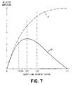
- FIG. 7 illustrates that a 1 to 3 ratio generates the maximum amount of second harmonic signal but that the other ratios just mentioned provide sufficient second harmonic amplitude.
- FIG. 7 also shows the amount of fundamental generated in each case. Since the fundamental amplitude is generally larger than the harmonic, the actual amplitude of the fundamental is not too important as long as it remains sufficiently above zero, as it does for all of the ratios from 1:5 to 1:2. The fundamental has a reduced but sufficient amplitude for the 1:5 ratio in particular.
Landscapes
- Moving Of The Head To Find And Align With The Track (AREA)
- Adjustment Of The Magnetic Head Position Track Following On Tapes (AREA)
- Control Of Position Or Direction (AREA)
Applications Claiming Priority (2)
| Application Number | Priority Date | Filing Date | Title |
|---|---|---|---|
| US108905 | 1979-12-31 | ||
| US06/108,905 US4286296A (en) | 1979-12-31 | 1979-12-31 | Transducer positioning system |
Publications (3)
| Publication Number | Publication Date |
|---|---|
| EP0031500A2 true EP0031500A2 (de) | 1981-07-08 |
| EP0031500A3 EP0031500A3 (en) | 1981-09-16 |
| EP0031500B1 EP0031500B1 (de) | 1983-11-09 |
Family
ID=22324741
Family Applications (1)
| Application Number | Title | Priority Date | Filing Date |
|---|---|---|---|
| EP80107634A Expired EP0031500B1 (de) | 1979-12-31 | 1980-12-04 | Servosystem zur Spurlagerelung eines Kopfträgers |
Country Status (4)
| Country | Link |
|---|---|
| US (1) | US4286296A (de) |
| EP (1) | EP0031500B1 (de) |
| JP (1) | JPS5698756A (de) |
| DE (1) | DE3065558D1 (de) |
Cited By (2)
| Publication number | Priority date | Publication date | Assignee | Title |
|---|---|---|---|---|
| EP0108224A1 (de) * | 1982-11-01 | 1984-05-16 | International Business Machines Corporation | Spurnachlaufsystem mit unterliegenden Servospuren für einen magnetischen Plattenspeicher |
| EP0108226A1 (de) * | 1982-11-01 | 1984-05-16 | International Business Machines Corporation | System zum Codieren von Servospuren in einem Plattenspeicher |
Families Citing this family (17)
| Publication number | Priority date | Publication date | Assignee | Title |
|---|---|---|---|---|
| US4371902A (en) * | 1980-06-30 | 1983-02-01 | International Business Machines Corporation | Disk initialization method |
| US4471396A (en) * | 1981-05-14 | 1984-09-11 | Seagate Technology | Disc recording apparatus including integral track zero and crash stop means |
| EP0141499A1 (de) * | 1983-08-31 | 1985-05-15 | Memorex Corporation | Servotechnik für einen Plattenantrieb |
| US4530020A (en) * | 1984-06-06 | 1985-07-16 | Dma Systems | Self-timed runout correction pattern |
| US5070421A (en) * | 1987-09-25 | 1991-12-03 | Fuji Xerox Co., Ltd. | Magnetic disk system having tracking control using recorded information |
| US5001579A (en) * | 1988-05-27 | 1991-03-19 | Eastman Kodak Company | Method and apparatus for centering a transducer over a recorded track on a rotary storage medium |
| US5568331A (en) * | 1989-10-27 | 1996-10-22 | Hitachi, Ltd. | Method of head positioning and magnetic recording disk drive using the same |
| US6028731A (en) * | 1996-03-29 | 2000-02-22 | Bond; Charles R. | Method and system for providing servo signals to a magnetic head positioning system of disk drive |
| JP2003296911A (ja) * | 2002-03-29 | 2003-10-17 | Toshiba Corp | 磁気記録媒体およびこれを用いた磁気記録再生装置 |
| US8369190B2 (en) * | 2010-06-15 | 2013-02-05 | Texas Instruments Incorporated | Proximity sensing system |
| US8817414B1 (en) | 2011-09-28 | 2014-08-26 | Marvell International Ltd. | Data detector for detecting data in presence of control signals |
| US9336829B2 (en) | 2011-11-21 | 2016-05-10 | Marvell International Ltd. | Data recording medium, method for generating a reference clock signal, and data storage device |
| US8922926B2 (en) | 2011-11-21 | 2014-12-30 | Agency for Science, Technology Research | Data recording medium and method for generating a reference clock signal |
| US9070410B2 (en) * | 2012-07-20 | 2015-06-30 | Marvell International Ltd. | Recording media, data storage devices, and methods for determining a position error signal in a recording medium |
| US9117472B1 (en) | 2013-02-28 | 2015-08-25 | Marvell International Ltd. | Processing a data signal with an embedded position signal |
| US9178531B1 (en) * | 2013-04-24 | 2015-11-03 | Seagate Technology Llc | Servo gray code check bits |
| WO2015041604A1 (en) * | 2013-09-17 | 2015-03-26 | Agency For Science, Technology And Research | Magnetic disk, method of track following on a magnetic disk, and method of writing a servo pattern in a dedicated servo layer of a magnetic disk |
Citations (3)
| Publication number | Priority date | Publication date | Assignee | Title |
|---|---|---|---|---|
| US3691543A (en) * | 1971-02-08 | 1972-09-12 | Ibm | Positioning system including servo track configuration and associated demodulator |
| US3808486A (en) * | 1972-08-25 | 1974-04-30 | Information Storage Systems | Selective frequency compensation for a servo system |
| US3893180A (en) * | 1974-01-02 | 1975-07-01 | Honeywell Inf Systems | Transducer positioning system |
Family Cites Families (5)
| Publication number | Priority date | Publication date | Assignee | Title |
|---|---|---|---|---|
| GB987357A (en) * | 1962-11-30 | 1965-03-24 | Ibm | Memory system employing a magnetic recording medium |
| US3534344A (en) * | 1967-12-21 | 1970-10-13 | Ibm | Method and apparatus for recording and detecting information |
| GB1396834A (en) * | 1973-01-31 | 1975-06-04 | Ibm | Data storage apparatus |
| US3959820A (en) * | 1974-09-16 | 1976-05-25 | Honeywell Information Systems, Inc. | System for increasing the number of data tracks in a magnetic recording system |
| US4000232A (en) * | 1975-09-23 | 1976-12-28 | Mobil Oil Corporation | Method of pelletizing plastic material |
-
1979
- 1979-12-31 US US06/108,905 patent/US4286296A/en not_active Expired - Lifetime
-
1980
- 1980-12-04 EP EP80107634A patent/EP0031500B1/de not_active Expired
- 1980-12-04 DE DE8080107634T patent/DE3065558D1/de not_active Expired
- 1980-12-19 JP JP17913580A patent/JPS5698756A/ja active Granted
Patent Citations (3)
| Publication number | Priority date | Publication date | Assignee | Title |
|---|---|---|---|---|
| US3691543A (en) * | 1971-02-08 | 1972-09-12 | Ibm | Positioning system including servo track configuration and associated demodulator |
| US3808486A (en) * | 1972-08-25 | 1974-04-30 | Information Storage Systems | Selective frequency compensation for a servo system |
| US3893180A (en) * | 1974-01-02 | 1975-07-01 | Honeywell Inf Systems | Transducer positioning system |
Non-Patent Citations (4)
| Title |
|---|
| IBM TECHNICAL DISCLOSURE BULLETIN, No. 7, December 1978, New York, USA FRASER: "FM processing of position error signals", Pages 3030-3031. * |
| IBM TECHNICAL DISCLOSURE BULLETIN, Vol. 16, No. 11, April 1974 New York, USA WALLIS:"Tri-bit servo pattern", pages 3757-3759. * Whole article * * |
| IEEE TRANSACTIONS ON MAGNETICS, Vol. MAG-14, No. 4, July 1978 New York, USA SIDMAN: "An adaptive filter for the processing of postition error signal in disk drives",pages 185-187. * |
| IEEE TRANSACTIONS ON MAGNETICS, Vol. MAG-14, No. 4, July 1978, New York, USA OSWALD: "Head positioning servo design for the IBM 3344/3350 disk files", pages 176-177. * |
Cited By (2)
| Publication number | Priority date | Publication date | Assignee | Title |
|---|---|---|---|---|
| EP0108224A1 (de) * | 1982-11-01 | 1984-05-16 | International Business Machines Corporation | Spurnachlaufsystem mit unterliegenden Servospuren für einen magnetischen Plattenspeicher |
| EP0108226A1 (de) * | 1982-11-01 | 1984-05-16 | International Business Machines Corporation | System zum Codieren von Servospuren in einem Plattenspeicher |
Also Published As
| Publication number | Publication date |
|---|---|
| EP0031500A3 (en) | 1981-09-16 |
| JPS6120945B2 (de) | 1986-05-24 |
| US4286296A (en) | 1981-08-25 |
| EP0031500B1 (de) | 1983-11-09 |
| JPS5698756A (en) | 1981-08-08 |
| DE3065558D1 (en) | 1983-12-15 |
Similar Documents
| Publication | Publication Date | Title |
|---|---|---|
| EP0031500B1 (de) | Servosystem zur Spurlagerelung eines Kopfträgers | |
| US7832084B2 (en) | Methods for recording servo information | |
| US6462904B1 (en) | Timing based servo system for magnetic tape systems | |
| US4979051A (en) | Bimodal multi-track magnetic head | |
| US4101942A (en) | Track following servo system and track following code | |
| US4587579A (en) | System for position detection on a rotating disk | |
| US4975791A (en) | Recording system having head transducers with controlled skew | |
| US6091565A (en) | Head assembly having a single pass servo writer | |
| US4476503A (en) | Method for the recognition of an edge of a magnetic medium and a device for implementation of the method | |
| EP0194603A2 (de) | Gerät mit kombiniertem Magnetkopf | |
| US4488188A (en) | Buried servo recording system using phase encoded servo pattern | |
| US5291348A (en) | High density servo tracking | |
| US6330123B1 (en) | Head assembly having a single pass servo writer | |
| US7199958B2 (en) | Servo head with varying write gap width | |
| EP0447460B1 (de) | System mit doppelter referenzschiene | |
| WO1993007612A1 (en) | Tracking control apparatus including a servo head having a tapered transducing gap | |
| US5790341A (en) | Method and apparatus for reducing servo interference in a magneto-resistive head using skew between head and servo pattern | |
| US6078463A (en) | Method and system for generating a position error signal from recorded servo data tracks containing information represented by longitudinally spaced, magnetic transitions | |
| EP0645764B1 (de) | Verfahren und Vorrichtung zur Positionnierung mittels Phasenmodulation in einer Speichereinheit mit direktem Zugriff | |
| EP0923078A1 (de) | Servomuster für Bandantrieb mit Linearaufzeichnungs-Servospurfolge und dieses verwendendes Positionsabfühlsystem und -verfahren | |
| JPS623475A (ja) | 磁気デイスク | |
| JPS5927007B2 (ja) | 磁気ヘツド | |
| JPS61246965A (ja) | 磁気デイスク装置 | |
| JPS61182681A (ja) | フレキシブルデイスク装置の保守方法 |
Legal Events
| Date | Code | Title | Description |
|---|---|---|---|
| PUAI | Public reference made under article 153(3) epc to a published international application that has entered the european phase |
Free format text: ORIGINAL CODE: 0009012 |
|
| AK | Designated contracting states |
Designated state(s): DE FR GB |
|
| PUAL | Search report despatched |
Free format text: ORIGINAL CODE: 0009013 |
|
| AK | Designated contracting states |
Designated state(s): DE FR GB |
|
| 17P | Request for examination filed |
Effective date: 19811009 |
|
| GRAA | (expected) grant |
Free format text: ORIGINAL CODE: 0009210 |
|
| AK | Designated contracting states |
Designated state(s): DE FR GB |
|
| REF | Corresponds to: |
Ref document number: 3065558 Country of ref document: DE Date of ref document: 19831215 |
|
| ET | Fr: translation filed | ||
| PLBE | No opposition filed within time limit |
Free format text: ORIGINAL CODE: 0009261 |
|
| STAA | Information on the status of an ep patent application or granted ep patent |
Free format text: STATUS: NO OPPOSITION FILED WITHIN TIME LIMIT |
|
| 26N | No opposition filed | ||
| PGFP | Annual fee paid to national office [announced via postgrant information from national office to epo] |
Ref country code: GB Payment date: 19901119 Year of fee payment: 11 |
|
| PGFP | Annual fee paid to national office [announced via postgrant information from national office to epo] |
Ref country code: FR Payment date: 19901122 Year of fee payment: 11 |
|
| PGFP | Annual fee paid to national office [announced via postgrant information from national office to epo] |
Ref country code: DE Payment date: 19901231 Year of fee payment: 11 |
|
| PG25 | Lapsed in a contracting state [announced via postgrant information from national office to epo] |
Ref country code: GB Effective date: 19911204 |
|
| GBPC | Gb: european patent ceased through non-payment of renewal fee | ||
| PG25 | Lapsed in a contracting state [announced via postgrant information from national office to epo] |
Ref country code: FR Effective date: 19920831 |
|
| PG25 | Lapsed in a contracting state [announced via postgrant information from national office to epo] |
Ref country code: DE Effective date: 19920901 |
|
| REG | Reference to a national code |
Ref country code: FR Ref legal event code: ST |